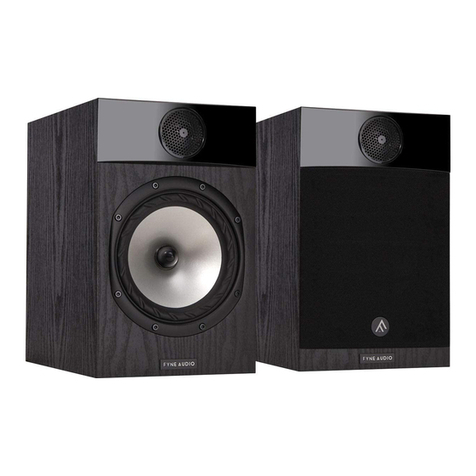
Fyne Audio F1-5 Owner's manual

F1-5, F1-8
FYNE ADVICE
ESSENTIAL INFORMATION GUIDE

TABLE OF CONTENTS
1. Introduction
2. Technology
3. Positioning
4. Stand Mounting
5. Amplierchoice
6. Cable choice
7. Connecting speaker cables
8. Earth connections
9. Presence Control
10. Care of cabinet
11. Warranty
12. Specication

2
1 INTRODUCTION
Thank you for choosing Fyne Audio F1 loudspeakers, proudly designed by our experienced
team of engineers, and constructed to the highest standards by artisans in our own facility in
Scotland. We believe they will give you many years of listening pleasure.
• Before installing these loudspeakers please read this manual in full, both for safety
reasons and to ensure you achieve the best performance possible.
• To prevent injury or damage when unpacking the loudspeakers, please do not use the
protective bag to lift them in case it tears.
• Please retain packing for possible future use.
• Thesespeakersmustalwaysbeconnectedtoasuitableamplierandnevertoa
mains supply.
Supplied accessories:
• Self adhesive feet (x8)
• Bi-wire links (x4)- F1-8 only

3
2 TECHNOLOGY
Our experienced team of acoustic and
product design engineers have been in the
loudspeaker industry for very many years.
Since coming together to form Fyne Audio,
they have been augmenting their existing
skills and developing new technologies
to ensure that we can offer best in class
performance through technical innovation
and advanced manufacturing techniques.
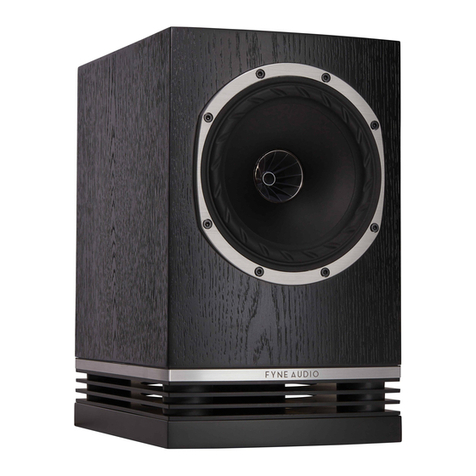
ISOFLARE™ POINT SOURCE DRIVER
Fyne Audio’s IsoFlare™ driver is a point
source system whereby the bass / midrange
driver shares a common centre with the
high frequency unit. Providing outstanding
stereo imaging even off axis, energy
is radiated isotropically with constant
directivityfollowingtheareofthedriver
cone. Sound is produced emanating from a
single point.
To fully optimise the driver performance,
every aspect of this meticulous design has
been considered. Eliminating unwanted
vibrations which would be detrimental
to the sound quality, our IsoFlare™ point
source drivers are built around a custom
tooled rigid cast aluminium chassis.
A vented rear chamber in the carefully
optimised HF magnet assembly places
low frequency resonance well below
the crossover region. Pushing the break
up mode well above the level of human
hearing, the highly rigid magnesium high
frequency diaphragm delivers a smooth and
extended response. The unique geometry of
the high frequency unit’s waveguide provides
aatfrequencyresponseandavoids
internalreections.
The HF diaphragm provides a natural and
unstressed performance, terminated by a
Polyester surround to optimally terminate
energy. The HF unit annular waveguide has
a computer optimised expansion rate and
geometrytoprovideatfrequencyresponse
andavoidinternalreections.
On the low frequency section, FyneFluteTM
surround technology more effectively
terminates cone energy, by providing a non-
homogeneous interface, eliminating harmful
resonances. The geometry is optimised by
advanced computer Finite Element Analysis.
Amulti-brepaperconegivesnatural
sounding midrange and clean transient
behaviour, while the high power LF motor
system uses a ferrite magnet.

4
CROSSOVER
Although simple in topology, the design is
computeroptimised,netunedsubjectively
by critical auditioning.
The crossover makes use of high quality
precision components, including low loss LF
laminated iron core inductors and Claritycap®
high grade polypropylene capacitors. High
quality gold plated WBT Nextgen™ terminals
are used, together with Van den Hul®
Matched Crystal OFC copper internal wiring,
with high purity silver coating, for transparent
signal transfer. The components are hard
wiredonbreboardpanelstominimise
vibration, using a special mastic.
Cryogenic treatment of the complete
crossover relaxes stresses in materials and
solder joints to maximise signal transparency.
Agroundingterminalisttedtominimisethe
effect of radio frequency interference masking
nedetail.
BASSTRAX™ TRACTRIX DIFFUSER SYSTEM
The F1-5 and F1-8 employ a downwards
ringportarrangement.Belowtheventin
the base of the loudspeaker, the BassTrax™
Tractrixprolediffuserisusedtoconvertthe
plain wave energy to an expanding spherical
360-degree wavefront, dispersing energy
uniformly into the room.
ThisTractrixprolehasbeenpreviously
applied to horn loudspeakers by Voight in
the 1920’s, but the application to a diffuser
of this type is novel and subject of a patent
application.
TheBassTrax™Tractrixproleisknown
to maintain a 90 degree angle at each
intersection of the expanding wavefront, thus
avoidingreections.Thiscleverarrangement
also makes the loudspeaker less critical of
room positioning.
ENCLOSURE
The high density birch ply construction
is pressed to ensure an extremely rigid
structure to ensure low colouration. The
drive unit is coupled to internal bracing
panels through damping material to absorb
energy in the case of the F1-8.
The machined aluminium platform provides
exceptional stability for precise low
frequency performance and resolution of
nedetail,alsobeinganintegralpartofthe
BassTrax™ diffuser system.

5
POWER AMPLIFIER
LEFT
-+RIGHT
-+
TO RIGHT
SPEAKER
LEFT SPEAKER
TO 'GROUND' OR 'EARTH'
CONNECTION ON AMPLIFIER
(OPTIONAL)
TO RIGHT
SPEAKER
TO 'GROUND' OR 'EARTH'
CONNECTION ON AMPLIFIER
(OPTIONAL)
LOW FREQUENCY
POWER AMPLIFIER
LEFT
-+RIGHT
-+
HIGH FREQUENCY
POWER AMPLIFIER
LEFT
-+RIGHT
-+
TO RIGHT
SPEAKER
FIG 7. PRESENSE ADJUSTMENT
+4 dB
+2 dB
0 dB
-2 dB
-4 dB
100 Hz 1 kHz 10 kHz 20 kHz
0.5 METRE
MINIMUM
1.5 TO 4.5 METRES
1 METRE
MINIMUM
POWER AMPLIFIER
LEFT
-+RIGHT
-+
TO RIGHT
SPEAKER
TO 'GROUND' OR 'EARTH'
CONNECTION ON AMPLIFIER
(OPTIONAL)
SINGLE WIRE MODE
LEFT SPEAKER
POWER AMPLIFIER
LEFT
-+RIGHT
-+
TO RIGHT
SPEAKER
TO 'GROUND' OR 'EARTH'
CONNECTION ON AMPLIFIER
(OPTIONAL)
BI-WIRE MODE
LEFT SPEAKERLEFT SPEAKER
BI-AMP MODE
1
3 POSITIONING
The loudspeakers should be positioned
approximately 1.5 – 4.5m apart (5 – 15 feet),
ideally no closer than 0.5m (20 inches) from
the rear wall and no closer than 1m (3 feet)
from the side walls (Fig 1).
Some degree of experimentation will provide
the best results, especially with toe in
towards the listener, to give the best stereo
imaging.

6
4 STAND MOUNTING
For optimum performance, we strongly recommend the use of Fyne Audio’s dedicated
loudspeakerstandwiththeF1-8.Instructionsonhowtoafxtheloudspeakertothestandare
included with the stand and should be followed carefully, both for reasons of safety and to
ensure you achieve the best sound possible.
If you decide however to make use of a third party stand design, it should be rigid and well
damped. The centre of the drive unit should be approximately at ear height when seated.
The F1-5 should similarly be mounted on an appropriate stand. However, bookshelf
placement may be preferred, although there will be a degree of compromise in terms of
stereo imaging and bass performance.
To prevent both personal injury and damage to the loudspeaker, ensure the stand is
stable and capable of supporting the weight of the loudspeaker.
To prevent slipping and to avoid scratching the underneath of the loudspeaker, 4 self adhesive
feet are provided for each one.

7
5 AMPLIFIER
CHOICE
Theadvisablerangeofamplier
powersisdetailedintheSpecication.
Responsible use with higher powered
ampliersispossible,duetotherobust
design of these loudspeakers.
Wedonotadvocateanyspecic
ampliertechnology,i.e.transistor
versus valve (tube). As with any high
resolution loudspeaker system, it is
thequalityoftheamplicationthat
is paramount in extracting maximum
performance from your loudspeakers.
Some customers may wish to use
valve(tube)ampliessuchassingle
ended triodes, with output powers less
than the minimum recommendation.
This will not cause damage to the
loudspeakers, but will restrict the
maximum volume and dynamic range,
especially in large rooms.
If you are considering the purchase
ofanewamplier,yourdealerwillbe
able to give you recommendations that
work well.
6 CABLE
CHOICE
It is important to use cables of
appropriate quality for such a high
performance loudspeaker. While from
a technical perspective, low electrical
resistance is necessary to minimise
lossesandmaximiseamplier
damping, the physical construction
of the cable including conductor type
and purity, together with insulation
characteristics have considerable
inuenceonthesoundquality.The
optimum cable is both subjective and
system dependent; your dealer will be
able to give advice.
Cables should be terminated in high
quality connectors, either 4mm banana
or spade. We would recommend the
use of WBT Nextgen™ connectors.

8
7 CONNECTING SPEAKER
CABLES
Ensure the amplier is switched off before connecting cables, to avoid damage.
F1-5
The F1-5 is provided with one set of speaker terminals. Ensure connections are made
positivetopositiveandnegativetonegativebetweentheloudspeakerandtheamplier(Fig2).
POWER AMPLIFIER
LEFT
-+RIGHT
-+
TO RIGHT
SPEAKER
LEFT SPEAKER
TO 'GROUND' OR 'EARTH'
CONNECTION ON AMPLIFIER
(OPTIONAL)
TO RIGHT
SPEAKER
TO 'GROUND' OR 'EARTH'
CONNECTION ON AMPLIFIER
(OPTIONAL)
LOW FREQUENCY
POWER AMPLIFIER
LEFT
-+RIGHT
-+
HIGH FREQUENCY
POWER AMPLIFIER
LEFT
-+RIGHT
-+
TO RIGHT
SPEAKER
FIG 7. PRESENSE ADJUSTMENT
+4 dB
+2 dB
0 dB
-2 dB
-4 dB
100 Hz 1 kHz 10 kHz 20 kHz
0.5 METRE
MINIMUM
1.5 TO 4.5 METRES
1 METRE
MINIMUM
POWER AMPLIFIER
LEFT
-+RIGHT
-+
TO RIGHT
SPEAKER
TO 'GROUND' OR 'EARTH'
CONNECTION ON AMPLIFIER
(OPTIONAL)
SINGLE WIRE MODE
LEFT SPEAKER
POWER AMPLIFIER
LEFT
-+RIGHT
-+
TO RIGHT
SPEAKER
TO 'GROUND' OR 'EARTH'
CONNECTION ON AMPLIFIER
(OPTIONAL)
BI-WIRE MODE
LEFT SPEAKER
LEFT SPEAKER
BI-AMP MODE
2

9
F1-8
The F1-8 is provided with two sets of terminals, one for the HF and one for the LF
section. Wiring may be done in either single wire mode or bi-wire mode. The latter
will provide optimum performance.
Whenusingasinglecable,wireasshown(Fig.3),ttingthelinkcablesprovided.
The best sound quality is generally achieved when connecting to the HF terminals.
Forbi-wireoperation,ensurethelinkwiresarenottted,andwirewithtwosetsof
cable, or a dedicated bi-wire cable (Fig 4). This will ensure the best possible sound
quality.
POWER AMPLIFIER
LEFT
-+RIGHT
-+
TO RIGHT
SPEAKER
LEFT SPEAKER
TO 'GROUND' OR 'EARTH'
CONNECTION ON AMPLIFIER
(OPTIONAL)
TO RIGHT
SPEAKER
TO 'GROUND' OR 'EARTH'
CONNECTION ON AMPLIFIER
(OPTIONAL)
LOW FREQUENCY
POWER AMPLIFIER
LEFT
-+RIGHT
-+
HIGH FREQUENCY
POWER AMPLIFIER
LEFT
-+RIGHT
-+
TO RIGHT
SPEAKER
FIG 7. PRESENSE ADJUSTMENT
+4 dB
+2 dB
0 dB
-2 dB
-4 dB
100 Hz 1 kHz 10 kHz 20 kHz
0.5 METRE
MINIMUM
1.5 TO 4.5 METRES
1 METRE
MINIMUM
POWER AMPLIFIER
LEFT
-+RIGHT
-+
TO RIGHT
SPEAKER
TO 'GROUND' OR 'EARTH'
CONNECTION ON AMPLIFIER
(OPTIONAL)
SINGLE WIRE MODE
LEFT SPEAKER
POWER AMPLIFIER
LEFT
-+RIGHT
-+
TO RIGHT
SPEAKER
TO 'GROUND' OR 'EARTH'
CONNECTION ON AMPLIFIER
(OPTIONAL)
BI-WIRE MODE
LEFT SPEAKERLEFT SPEAKER
BI-AMP MODE
4
POWER AMPLIFIER
LEFT
-+RIGHT
-+
TO RIGHT
SPEAKER
LEFT SPEAKER
TO 'GROUND' OR 'EARTH'
CONNECTION ON AMPLIFIER
(OPTIONAL)
TO RIGHT
SPEAKER
TO 'GROUND' OR 'EARTH'
CONNECTION ON AMPLIFIER
(OPTIONAL)
LOW FREQUENCY
POWER AMPLIFIER
LEFT
-+RIGHT
-+
HIGH FREQUENCY
POWER AMPLIFIER
LEFT
-+RIGHT
-+
TO RIGHT
SPEAKER
FIG 7. PRESENSE ADJUSTMENT
+4 dB
+2 dB
0 dB
-2 dB
-4 dB
100 Hz 1 kHz 10 kHz 20 kHz
0.5 METRE
MINIMUM
1.5 TO 4.5 METRES
1 METRE
MINIMUM
POWER AMPLIFIER
LEFT
-+RIGHT
-+
TO RIGHT
SPEAKER
TO 'GROUND' OR 'EARTH'
CONNECTION ON AMPLIFIER
(OPTIONAL)
SINGLE WIRE MODE
LEFT SPEAKER
POWER AMPLIFIER
LEFT
-+RIGHT
-+
TO RIGHT
SPEAKER
TO 'GROUND' OR 'EARTH'
CONNECTION ON AMPLIFIER
(OPTIONAL)
BI-WIRE MODE
LEFT SPEAKER
LEFT SPEAKER
BI-AMP MODE
3

10
A further option is bi-amping, where the
LF and HF sections of the loudspeaker
areeachdrivenfromtheirownamplier,
for further enhancement in sound quality.
Eithertwostereopowerampliersorfour
monoblockampliersmaybeused.Ifusing
twostereoampliers,itisrecommended
that one is used as the LF channel to both
loudspeakers and the other HF (Fig 5). To
avoid amplier damage, the link cables
must not be in place.
POWER AMPLIFIER
LEFT
-+RIGHT
-+
TO RIGHT
SPEAKER
LEFT SPEAKER
TO 'GROUND' OR 'EARTH'
CONNECTION ON AMPLIFIER
(OPTIONAL)
TO RIGHT
SPEAKER
TO 'GROUND' OR 'EARTH'
CONNECTION ON AMPLIFIER
(OPTIONAL)
LOW FREQUENCY
POWER AMPLIFIER
LEFT
-+RIGHT
-+
HIGH FREQUENCY
POWER AMPLIFIER
LEFT
-+RIGHT
-+
TO RIGHT
SPEAKER
FIG 7. PRESENSE ADJUSTMENT
+4 dB
+2 dB
0 dB
-2 dB
-4 dB
100 Hz 1 kHz 10 kHz 20 kHz
0.5 METRE
MINIMUM
1.5 TO 4.5 METRES
1 METRE
MINIMUM
POWER AMPLIFIER
LEFT
-+RIGHT
-+
TO RIGHT
SPEAKER
TO 'GROUND' OR 'EARTH'
CONNECTION ON AMPLIFIER
(OPTIONAL)
SINGLE WIRE MODE
LEFT SPEAKER
POWER AMPLIFIER
LEFT
-+RIGHT
-+
TO RIGHT
SPEAKER
TO 'GROUND' OR 'EARTH'
CONNECTION ON AMPLIFIER
(OPTIONAL)
BI-WIRE MODE
LEFT SPEAKERLEFT SPEAKER
BI-AMP MODE
5

11
The F1-5 and F1-8 are provided with an adjustment control on the front panel, to achieve
optimal performance in terms of both the listening environment and listener preference.
This‘Presence’controlonlyaffectsthelowertrebleregionof2.5-5.0kHz,andinuences
articulation and vocal clarity and has an effect on image depth (Fig 6).
Start with the control in the central (level) position and make small adjustments with well
recorded programme material that you are familiar with. Achieving the correct presentation is
similar to focusing the lens on a camera, to achieve the most realistic sound.
POWER AMPLIFIER
LEFT
-+RIGHT
-+
TO RIGHT
SPEAKER
LEFT SPEAKER
TO 'GROUND' OR 'EARTH'
CONNECTION ON AMPLIFIER
(OPTIONAL)
TO RIGHT
SPEAKER
TO 'GROUND' OR 'EARTH'
CONNECTION ON AMPLIFIER
(OPTIONAL)
LOW FREQUENCY
POWER AMPLIFIER
LEFT
-+RIGHT
-+
HIGH FREQUENCY
POWER AMPLIFIER
LEFT
-+RIGHT
-+
TO RIGHT
SPEAKER
FIG 7. PRESENSE ADJUSTMENT
+4 dB
+2 dB
0 dB
-2 dB
-4 dB
100 Hz 1 kHz 10 kHz 20 kHz
0.5 METRE
MINIMUM
1.5 TO 4.5 METRES
1 METRE
MINIMUM
POWER AMPLIFIER
LEFT
-+RIGHT
-+
TO RIGHT
SPEAKER
TO 'GROUND' OR 'EARTH'
CONNECTION ON AMPLIFIER
(OPTIONAL)
SINGLE WIRE MODE
LEFT SPEAKER
POWER AMPLIFIER
LEFT
-+RIGHT
-+
TO RIGHT
SPEAKER
TO 'GROUND' OR 'EARTH'
CONNECTION ON AMPLIFIER
(OPTIONAL)
BI-WIRE MODE
LEFT SPEAKERLEFT SPEAKER
BI-AMP MODE
6PRESENCE ADJUSTMENT
8 EARTH CONNECTION
The loudspeaker is provided with an earth or ground connection, connected to the drive unit
chassis. The purpose of this is to ground any radio frequency interference that may get back
totheamplier,reducingnedetailandresolution.Aseparateearthwiremaybeusedforthis
purpose, but best results will be obtained by using a dedicated screened loudspeaker cable.
9 PRESENCE CONTROL

12
10 CARE OF
CABINET
The cabinet may be cleaned with a
microbercloth.Occasionallyuseahigh
quality non-silicone furniture polish on
the high gloss wooden areas. As wood is a
natural material, avoid exposure to extremes
of heat, humidity and direct sunlight for
extended periods of time.
If unused for long periods of time, you may
wish to cover the loudspeakers with the
cloth bags they were packaged in, to provide
protection.
On no account use solvents or abrasive
materials, as this will cause damage and
invalidate the warranty.

13
11 WARRANTY
No maintenance of the loudspeaker is
necessary.
Please register your FYNE AUDIO LIMITED
product online at www.fyne audio.com. All
of our products have been produced and
testedwithcareandprecisiontogiverst-
class service.
All passive loudspeakers are guaranteed
for a period of 7 years from the date of
purchase from an authorised FYNE AUDIO
LIMITED dealer. This warranty is subject
to the absence or evidence of misuse,
overload, or accidental damage, applies only
to the registered owner, and covers only
genuine FYNE AUDIO LIMITED products with
the original undamaged serial number.
All active and electronic components are
guaranteed for a period of 2 years from
the date of purchase from an authorised
FYNE AUDIO LIMITED dealer subject to the
absence of, or evidence of, misuse, overload
or accidental damage.
If at any time during this warranty period
the equipment proves to be defective for
any reason other than accident, misuse,
neglect,unauthorisedmodication,incorrect
installation or connection, matched with
improper equipment or fair wear and tear,
we will repair any such manufacturing
defect or, at our option, replace it without
charge for labour, parts or return carriage.
If you suspect a problem with a FYNE AUDIO
LIMITEDproduct,intherstinstance,
discuss it with your FYNE AUDIO LIMITED
dealer. If you require further assistance
then we ask that you deal directly with your
local FYNE AUDIO LIMITED distributor. If you
cannot locate your distributor please
contact FYNE AUDIO LIMITED Customer
Services, via our website listed above or at
the e-mail enquiries@fyneaudio.com
Do not ship any product to FYNE AUDIO
LIMITED without previous authorisation.
LIABILITY
Other than the warranty and services set
out in this warranty, to the fullest extent
permitted by law, FYNE AUDIO LIMITED
and its Authorised Distributors shall not be
liable to you and/or any third party or entity
whatsoever for:- any loss, damages and/
or malfunction caused to any product(s)
which is/are connected to any of the FYNE
AUDIO LIMITED products any damages,
loss and liability (except for any personal
injuries or death), whether direct, indirect,
incidental, consequential special, punitive or
otherwise, howsoever caused by, arising out
of, or otherwise in relation to the installation,
delivery, use, service, repair, replacement
and/or maintenance of the FYNE AUDIO
LIMITED product; or any damages, loss and
liability (except for any personal injuries
or death) under this warranty in respect
of any act, omission, or negligence of any
of their technicians, employees, agents,
representatives or independent contractors
relating to the actual or purported
performance of any of the obligations under
this warranty.
Without limiting the above, the maximum
liability of the FYNE AUDIO LIMITED and
its Authorised Distributors under this
warranty shall not in any event or under any
circumstances exceed the actual purchase
price paid for the FYNE AUDIO LIMITED
product(s).

14
SPECIFICATIONS
F1-5
System type 2way,downwardsringport,
with BassTraxTM Tractrix diffuser*
Recommended amplier 30 - 100
power (Watt RMS)
Peak power handling (Watt peak) 200
Continuous power 50
handling (Watt RMS)
Sensitivity (2.83 Volt @ 1m) 87dB
Nominal impedance 8 Ohm
Frequency response 48Hz - 38kHz
(-6dB typical in room)
Drive unit complement 1 x 125mm IsoFlareTM point source driver,
multi-brebass/midrangecone,
FyneFluteTM surround with 19mm magnesium
dome compression tweeter, neodymium
magnet system
Crossover frequency 1.9kHz
Crossover type Single wired passive low loss, 2nd order low pass,
1st order high pass. Deep Cryogenically Treated
System adjustments Presence (2.5kHz - 5.0kHz) +/- 3dB
Dimensions - HxWxD 321 x 186 x 289mm
(12.6 x 7.3 x 11.4”)
Cabinet construction Pressed high density birch ply
* Patent applied for

15
F1-5
System type 2way,downwardsringport,
with BassTraxTM Tractrix diffuser*
Recommended amplier 30 - 100
power (Watt RMS)
Peak power handling (Watt peak) 200
Continuous power 50
handling (Watt RMS)
Sensitivity (2.83 Volt @ 1m) 87dB
Nominal impedance 8 Ohm
Frequency response 48Hz - 38kHz
(-6dB typical in room)
Drive unit complement 1 x 125mm IsoFlareTM point source driver,
multi-brebass/midrangecone,
FyneFluteTM surround with 19mm magnesium
dome compression tweeter, neodymium
magnet system
Crossover frequency 1.9kHz
Crossover type Single wired passive low loss, 2nd order low pass,
1st order high pass. Deep Cryogenically Treated
System adjustments Presence (2.5kHz - 5.0kHz) +/- 3dB
Dimensions - HxWxD 321 x 186 x 289mm
(12.6 x 7.3 x 11.4”)
Cabinet construction Pressed high density birch ply
* Patent applied for
F1-8
System type 2way,downwardsringport,
with BassTraxTM Tractrix diffuser*
Recommended amplier 30 - 180
power (Watt RMS)
Peak power handling (Watt peak) 360
Continuous power 90
handling (Watt RMS)
Sensitivity (2.83 Volt @ 1m) 91dB
Nominal impedance 8 Ohm
Frequency response 33Hz - 34kHz
(-6dB typical in room)
Drive unit complement 1 x 200mm IsoFlareTMpointsourcedriver,multi-bre
bass/ midrange cone, FyneFluteTM surround with
25mm magnesium dome compression tweeter,
ferrite magnet system
Crossover frequency 1.8kHz
Crossover type Bi-wired passive low loss, 2nd order low pass,
1st order high pass. Deep Cryogenically Treated
System adjustments Presence (2.5kHz - 5.0kHz) +/- 3dB
Dimensions - HxWxD 470 x 280 x 441mm
(18.5 x 11.0 x 17.4”)
Cabinet construction Pressed high density birch ply, internally braced
* Patent applied for

ENJOY.

WWW.FYNEAUDIO.COM
Thank you for choosing Fyne Audio loudspeakers, proudly designed
by our experienced team of engineers in Scotland, and constructed
to the highest standards.
FYNEAUDIO
@FyneAudio 10 September 2019
F6480 0010
This manual suits for next models
1
Table of contents
Other Fyne Audio Speakers manuals

Fyne Audio
Fyne Audio F500 Series Technical manual

Fyne Audio
Fyne Audio F1 Series Owner's manual

Fyne Audio
Fyne Audio F502SP Technical manual

Fyne Audio
Fyne Audio F300 Series Technical manual

Fyne Audio
Fyne Audio FA301iC Technical manual

Fyne Audio
Fyne Audio ADVICE F500 SP Series User manual

Fyne Audio
Fyne Audio VINTAGE TEN Technical manual

Fyne Audio
Fyne Audio F700 Series Technical manual

Fyne Audio
Fyne Audio VINTAGE CLASSIC X Technical manual