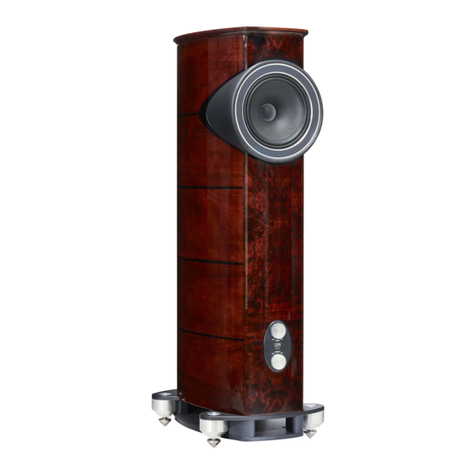
Fyne Audio VINTAGE TEN Technical manual

VINTAGE
TEN, TWELVE & FIFTEEN
FYNE ADVICE
ESSENTIAL INFORMATION GUIDE


TABLE OF CONTENTS
1. Introduction
2. Technology
3. Unpacking
6. Cable choice
7. Connecting speaker cables
8. Earth connections
9. Adjustments
10. Care of cabinet
11. Warranty

4
1 INTRODUCTION
Thank you for choosing Fyne Audio Vintage loudspeakers, proudly designed by our
experienced team of engineers, and constructed to the highest standards by artisans in our
own facility in Scotland. We believe they will give you many years of listening pleasure.
• Before installing these loudspeakers please read this manual in full, both for safety
reasons and to ensure you achieve the best performance possible.
• When unpacking, please follow the instructions carefully, to avoid causing possible
injury or damage. Please ensure you have the help of an assistant.
• Please retain packing for possible future use.
• Check contents of the accessories box
Your accessories box includes
• Floor coupling spike M12 (x8)
• Spike locking wheel (x8)
• Floor protection cups (x8)
• Tin wood wax (x1)
• Bi-wire links (x4)

5
2 TECHNOLOGY
Our experienced team of acoustic and
product design engineers have been in the
loudspeaker industry for very many years.
Since coming together to form Fyne Audio,
they have been augmenting their existing
skills and developing new technologies
to ensure that we can offer best in class
performance through technical innovation
and advanced manufacturing techniques.
The new Fyne Vintage Series takes the
developed by Dr Paul Mills for the award-
winning F1 Series and distils it into timeless
and distinctive period designs with a
journey to the industry leading expert he is
today.
ISOFLARE™ POINT SOURCE DRIVER
Fyne Audio’s IsoFlare™ driver is a point
source system whereby the bass / midrange
driver shares a common centre with the
high frequency unit. Providing outstanding
stereo imaging even off axis, energy
is radiated isotropically with constant
cone. Sound is produced emanating from a
single point.
To fully optimise the driver performance,
every aspect of this meticulous design has
been considered. Eliminating unwanted
vibrations which would be detrimental
to the sound quality, our IsoFlare™ point
source drivers are built around a custom
tooled rigid cast aluminium chassis.
A vented rear chamber in the substantial
Neodymium HF magnet places low
frequency resonance well below the
crossover region. Pushing the break up
mode well above the level of human
hearing, the highly rigid 75mm titanium
alloy high frequency diaphragm delivers a
smooth and extended response, while a
copper shorting ring provides low distortion.
The unique geometry of the high frequency
The HF diaphragm provides a natural and
unstressed performance, terminated by
a Mylar surround to optimally terminate
energy. Such a large diaphragm allows a very
low crossover frequency of 750Hz to the
bass / midrange cone, ensuring much of the
vocal range is handled by the tweeter.
The HF unit annular waveguide has a
computer optimised expansion rate and
high power edgewound aluminium HF voice
coil on Kapton® former eliminates thermal
compression.
On the low frequency section, the
FyneFlute™ surround effectively terminates
cone energy, without time-smearing. A
midrange and clean transient behaviour,
while the high power LF motor system uses
ferrite magnet, with rectangular copper
voice coil on an aluminium former, to aid
power dissipation. A copper shorting ring
on the pole piece reduces eddy currents,
reducing midrange distortion tenfold.
6
CROSSOVER
Although simple in topology, the design is
by critical auditioning.
The crossover makes use of high quality
precision components, including low loss LF
laminated iron core inductors, non-inductive
HF polypropylene capacitors. High quality
gold plated WBT Nextgen™ bi-wire terminals
are used, together with Van den Hul Matched
Crystal OFC wiring with high purity silver
coating, for transparent signal transfer. The
panels to minimise vibration, using a special
mastic.
A specially designed autotransformer using
the highest grade silicon steel laminations
impedance matches the HF compression
impregnation to eliminate distortion caused
by winding vibration.
Cryogenic treatment of the complete
crossover relaxes stresses in materials and
solder joints to maximise signal transparency.
effect of radio frequency interference masking
BASSTRAX™ TRACTRIX DIFFUSER SYSTEM
loading system. This loading system broadens
the tuning frequency to reduce cone excursion,
produced by the main internal port.
Below the vent in the base of the loudspeaker,
used to convert the plain wave energy to an
expanding spherical 360-degree wavefront,
dispersing energy uniformly into the room.
applied to horn loudspeakers by Voight in the
1920’s, but the application to a diffuser of this
type is novel and has been granted a patent.
maintain a 90 degree angle at each
intersection of the expanding wavefront, thus
also makes the loudspeaker less critical of
room positioning.
ENCLOSURE
The high density birch ply construction is
pressed to ensure an extremely rigid and
low colouration structure. The drive unit is
coupled to internal bracing panels through
damping material to absorb energy. Each
cabinet is uniquely crafted from individually
selected Walnut and Burr Walnut real wood
and accented with gold anodised metalwork.
Heavy duty support spikes enable precise
levelling, with the provision of machined
aluminium cups for protection on wooden

7
1
3 UNPACKING
This operation should be performed by two people to avoid injury or damage to the
loudspeaker, should it slip or fall.
Vintage Twelve and Fieen: these are shipped on wooden pallets. After removing the
cardboard lid, foam top cushion and cardboard sleeve, lift the loudspeaker off the wooden
pallet, using the straps provided (Fig. 1). The speaker can then be slid roughly into position,
while sitting on the foam bottom end cushions.

8
4 POSITIONING & FITTING FLOOR
COUPLING SPIKES
With the loudspeaker still located on the foam end cushions, start by positioning the
loudspeakers with their rear at least 0.5m from the rear wall. The proximity of a side wall
should be no closer than 1m (Fig. 2).
by toeing in the cabinets towards the listening position. The BassTrax™ diffuser
system however, will serve to make the loudspeaker less sensitive to boundary
conditions than with a conventional design.
LINK CABLES IN PLACE
LEFT SPEAKER
LINK CABLES REMOVED
LEFT SPEAKER
LINK CABLES REMOVED
LEFT SPEAKER
TO RIGHT
SPEAKER
LOW FREQUENCY
POWER AMPLIFIER
LEFT
-+RIGHT
-+
HIGH FREQUENCY
POWER AMPLIFIER
LEFT
-+RIGHT
-+
TO RIGHT
SPEAKER
FIG 7. PRESENSE ADJUSTMENT
FIG 6. HF ENERGY ADJUSTMENT
+4 dB
+2 dB
0 dB
-2 dB
-4 dB
100 Hz 1 kHz 10 kHz 20 kHz
+4 dB
+2 dB
0 dB
-2 dB
-4 dB
100 Hz 1 kHz 10 kHz 20 kHz
0.5 METRE
MINIMUM
1.5 TO 4.5 METRES
1 METRE
MINIMUM
POWER AMPLIFIER
LEFT
-+RIGHT
-+
TO RIGHT
SPEAKER
TO 'GROUND' OR 'EARTH'
CONNECTION ON AMPLIFIER
(OPTIONAL)
POWER AMPLIFIER
LEFT
-+RIGHT
-+
TO RIGHT
SPEAKER
TO 'GROUND' OR 'EARTH'
CONNECTION ON AMPLIFIER
(OPTIONAL)
TO 'GROUND' OR 'EARTH'
CONNECTION ON AMPLIFIER
(OPTIONAL)
2

9
LINK CABLES IN PLACE
LEFT SPEAKER
LINK CABLES REMOVED
LEFT SPEAKER
LINK CABLES REMOVED
LEFT SPEAKER
TO RIGHT
SPEAKER
LOW FREQUENCY
POWER AMPLIFIER
LEFT
-+RIGHT
-+
HIGH FREQUENCY
POWER AMPLIFIER
LEFT
-+RIGHT
-+
TO RIGHT
SPEAKER
FIG 7. PRESENSE ADJUSTMENT
FIG 6. HF ENERGY ADJUSTMENT
+4 dB
+2 dB
0 dB
-2 dB
-4 dB
100 Hz 1 kHz 10 kHz 20 kHz
+4 dB
+2 dB
0 dB
-2 dB
-4 dB
100 Hz 1 kHz 10 kHz 20 kHz
0.5 METRE
MINIMUM
1.5 TO 4.5 METRES
1 METRE
MINIMUM
POWER AMPLIFIER
LEFT
-+RIGHT
-+
TO RIGHT
SPEAKER
TO 'GROUND' OR 'EARTH'
CONNECTION ON AMPLIFIER
(OPTIONAL)
POWER AMPLIFIER
LEFT
-+RIGHT
-+
TO RIGHT
SPEAKER
TO 'GROUND' OR 'EARTH'
CONNECTION ON AMPLIFIER
(OPTIONAL)
TO 'GROUND' OR 'EARTH'
CONNECTION ON AMPLIFIER
(OPTIONAL)
4
Vintage Twelve & Fieen: referring to Fig. 3, with the help of an assistant, remove the foam
locking wheels. Repeat for the other side of the loudspeaker.
Vintage Ten:
coupling spikes and locking wheels. When the loudspeaker is in position, level by
adjusting the spikes and tighten the locking wheels (Fig. 4).
Ensure the protective cups are used under the spikes to avoid damage to wooden
LINK CABLES IN PLACE
LEFT SPEAKER
LINK CABLES REMOVED
LEFT SPEAKER
LINK CABLES REMOVED
LEFT SPEAKER
TO RIGHT
SPEAKER
LOW FREQUENCY
POWER AMPLIFIER
LEFT
-+RIGHT
-+
HIGH FREQUENCY
POWER AMPLIFIER
LEFT
-+RIGHT
-+
TO RIGHT
SPEAKER
FIG 7. PRESENSE ADJUSTMENT
FIG 6. HF ENERGY ADJUSTMENT
+4 dB
+2 dB
0 dB
-2 dB
-4 dB
100 Hz 1 kHz 10 kHz 20 kHz
+4 dB
+2 dB
0 dB
-2 dB
-4 dB
100 Hz 1 kHz 10 kHz 20 kHz
0.5 METRE
MINIMUM
1.5 TO 4.5 METRES
1 METRE
MINIMUM
POWER AMPLIFIER
LEFT
-+RIGHT
-+
TO RIGHT
SPEAKER
TO 'GROUND' OR 'EARTH'
CONNECTION ON AMPLIFIER
(OPTIONAL)
POWER AMPLIFIER
LEFT
-+RIGHT
-+
TO RIGHT
SPEAKER
TO 'GROUND' OR 'EARTH'
CONNECTION ON AMPLIFIER
(OPTIONAL)
TO 'GROUND' OR 'EARTH'
CONNECTION ON AMPLIFIER
(OPTIONAL)
3

10
5 AMPLIFIER
CHOICE
Responsible use with higher powered
design of these loudspeakers.
versus valve (tube). As with any high
resolution loudspeaker system, it is
is paramount in extracting maximum
performance from your loudspeakers.
Some customers may wish to use
ended triodes, with output powers less
than the minimum recommendation.
This will not cause damage to the
loudspeakers, but will restrict the
maximum volume and dynamic range,
especially in large rooms.
If you are considering the purchase
able to give you recommendations that
work well.
6 CABLE
CHOICE
It is important to use cables of
appropriate quality for such high
performance loudspeakers. While from
a technical perspective, an adequately
low electrical resistance is necessary
to minimise losses and maximise
construction of the cable including
conductor type and purity, together
with insulation characteristics have
quality. The optimum cable is both
subjective and system dependent; your
dealer will be able to give advice.
Cables should be terminated in high
quality connectors, either 4mm banana
or spade. We would recommend the
use of WBT Nextgen™ connectors.

11
LINK CABLES IN PLACE
LEFT SPEAKER
LINK CABLES REMOVED
LEFT SPEAKER
LINK CABLES REMOVED
LEFT SPEAKER
TO RIGHT
SPEAKER
LOW FREQUENCY
POWER AMPLIFIER
LEFT
-+RIGHT
-+
HIGH FREQUENCY
POWER AMPLIFIER
LEFT
-+RIGHT
-+
TO RIGHT
SPEAKER
FIG 7. PRESENSE ADJUSTMENT
FIG 6. HF ENERGY ADJUSTMENT
+4 dB
+2 dB
0 dB
-2 dB
-4 dB
100 Hz 1 kHz 10 kHz 20 kHz
+4 dB
+2 dB
0 dB
-2 dB
-4 dB
100 Hz 1 kHz 10 kHz 20 kHz
0.5 METRE
MINIMUM
1.5 TO 4.5 METRES
1 METRE
MINIMUM
POWER AMPLIFIER
LEFT
-+RIGHT
-+
TO RIGHT
SPEAKER
TO 'GROUND' OR 'EARTH'
CONNECTION ON AMPLIFIER
(OPTIONAL)
POWER AMPLIFIER
LEFT
-+RIGHT
-+
TO RIGHT
SPEAKER
TO 'GROUND' OR 'EARTH'
CONNECTION ON AMPLIFIER
(OPTIONAL)
TO 'GROUND' OR 'EARTH'
CONNECTION ON AMPLIFIER
(OPTIONAL)
7 CONNECTING SPEAKER
CABLES
Ensure the amplier is switched off before connecting cables, to avoid damage.
Ensure connections are made positive to positive and negative to negative between the
The loudspeakers are provided with two sets of terminals, one for the HF and one for the
LF section. Wiring may be done in either single wire mode or bi-wire mode. The latter will
provide optimum performance.
sound quality will generally be achieved when connecting to the HF terminals. For bi-wire
bi-wire cable (Fig. 7). This will ensure the best possible sound quality.
LINK CABLES IN PLACE
LEFT SPEAKER
LINK CABLES REMOVED
LEFT SPEAKER
LINK CABLES REMOVED
LEFT SPEAKER
TO RIGHT
SPEAKER
LOW FREQUENCY
POWER AMPLIFIER
LEFT
-+RIGHT
-+
HIGH FREQUENCY
POWER AMPLIFIER
LEFT
-+RIGHT
-+
TO RIGHT
SPEAKER
FIG 7. PRESENSE ADJUSTMENT
FIG 6. HF ENERGY ADJUSTMENT
+4 dB
+2 dB
0 dB
-2 dB
-4 dB
100 Hz 1 kHz 10 kHz 20 kHz
+4 dB
+2 dB
0 dB
-2 dB
-4 dB
100 Hz 1 kHz 10 kHz 20 kHz
0.5 METRE
MINIMUM
1.5 TO 4.5 METRES
1 METRE
MINIMUM
POWER AMPLIFIER
LEFT
-+RIGHT
-+
TO RIGHT
SPEAKER
TO 'GROUND' OR 'EARTH'
CONNECTION ON AMPLIFIER
(OPTIONAL)
POWER AMPLIFIER
LEFT
-+RIGHT
-+
TO RIGHT
SPEAKER
TO 'GROUND' OR 'EARTH'
CONNECTION ON AMPLIFIER
(OPTIONAL)
TO 'GROUND' OR 'EARTH'
CONNECTION ON AMPLIFIER
(OPTIONAL)
6 7
SINGLE WIRE MODE

12
LINK CABLES IN PLACE
LEFT SPEAKER
LINK CABLES REMOVED
LEFT SPEAKER
LINK CABLES REMOVED
LEFT SPEAKER
TO RIGHT
SPEAKER
LOW FREQUENCY
POWER AMPLIFIER
LEFT
-+RIGHT
-+
HIGH FREQUENCY
POWER AMPLIFIER
LEFT
-+RIGHT
-+
TO RIGHT
SPEAKER
FIG 7. PRESENSE ADJUSTMENT
FIG 6. HF ENERGY ADJUSTMENT
+4 dB
+2 dB
0 dB
-2 dB
-4 dB
100 Hz 1 kHz 10 kHz 20 kHz
+4 dB
+2 dB
0 dB
-2 dB
-4 dB
100 Hz 1 kHz 10 kHz 20 kHz
0.5 METRE
MINIMUM
1.5 TO 4.5 METRES
1 METRE
MINIMUM
POWER AMPLIFIER
LEFT
-+RIGHT
-+
TO RIGHT
SPEAKER
TO 'GROUND' OR 'EARTH'
CONNECTION ON AMPLIFIER
(OPTIONAL)
POWER AMPLIFIER
LEFT
-+RIGHT
-+
TO RIGHT
SPEAKER
TO 'GROUND' OR 'EARTH'
CONNECTION ON AMPLIFIER
(OPTIONAL)
TO 'GROUND' OR 'EARTH'
CONNECTION ON AMPLIFIER
(OPTIONAL)
A further option is bi-amping, where the
LF and HF sections of the loudspeaker
for further enhancement in sound quality.
that one is used as the LF channel to both
loudspeakers and the other HF (Fig. 8).
To avoid amplier damage, the bi-wire
link cables must not be in place.
8
8 EARTH CONNECTION
The loudspeaker is provided with an earth or ground connection, connected to the drive unit
chassis. The purpose of this is to ground any radio frequency interference that may get back
purpose, but best results will be obtained by using a dedicated screened loudspeaker cable.

13
9 ADJUSTMENTS
The Vintage Series is provided with two adjustment controls on the front panel, to achieve
optimal performance in terms of both the listening environment and listener preference.
The upper ‘Energy’ control alters the level of signal fed to the tweeter, from the crossover
point upwards, giving control over how bright the presentation sounds (Fig. 9).
The lower ‘Presence’ control only affects the lower treble region of 2.5 - 5.0kHz, and
Start with both controls in the central (level) position, and make small adjustments with well
recorded programme material that you are familiar with. Achieving the correct presentation
is equivalent to focusing the lens on a camera, to achieve the most realistic sound-staging
depth.
LINK CABLES IN PLACE
LEFT SPEAKER
LINK CABLES REMOVED
LEFT SPEAKER
LINK CABLES REMOVED
LEFT SPEAKER
TO RIGHT
SPEAKER
LOW FREQUENCY
POWER AMPLIFIER
LEFT
-+RIGHT
-+
HIGH FREQUENCY
POWER AMPLIFIER
LEFT
-+RIGHT
-+
TO RIGHT
SPEAKER
FIG 7. PRESENSE ADJUSTMENT
FIG 6. HF ENERGY ADJUSTMENT
+4 dB
+2 dB
0 dB
-2 dB
-4 dB
100 Hz 1 kHz 10 kHz 20 kHz
+4 dB
+2 dB
0 dB
-2 dB
-4 dB
100 Hz 1 kHz 10 kHz 20 kHz
0.5 METRE
MINIMUM
1.5 TO 4.5 METRES
1 METRE
MINIMUM
POWER AMPLIFIER
LEFT
-+RIGHT
-+
TO RIGHT
SPEAKER
TO 'GROUND' OR 'EARTH'
CONNECTION ON AMPLIFIER
(OPTIONAL)
POWER AMPLIFIER
LEFT
-+RIGHT
-+
TO RIGHT
SPEAKER
TO 'GROUND' OR 'EARTH'
CONNECTION ON AMPLIFIER
(OPTIONAL)
TO 'GROUND' OR 'EARTH'
CONNECTION ON AMPLIFIER
(OPTIONAL)
9HF ENERGY ADJUSTMENT
10 PRESENCE ADJUSTMENT

14
10 CARE OF CABINET
The cabinet may be dusted with a lint free cloth, such as muslin. As wood is a natural
material, avoid exposure to extremes of heat, humidity and direct sunlight for extended
periods of time.
If unused for long periods of time, you may wish to cover the loudspeakers with the cloth
bags they were packaged in, to provide protection.
On no account use solvents or abrasive materials, as this will cause damage and invalidate
the warranty.
The oiled walnut body of the cabinet should be treated sparingly with the wood wax provided,
signs of drying out, depending on temperature and humidity. Avoid contact with the front
CAUTION:
• Wood wax contains ALPHA PINENE- may produce an alergic reaction
• Keep out of reach of children
• Use in a well ventilated area. Never eat, drink or smoke during use
• Vapours may cause drowsiness or dizziness. In the case of excessive inhalation,
remove the person exposed to fresh air, keep warm and at rest
• In the event of eye contact, rince with clean water for 15 minutes
• In the event of skin contact, wash thoroughly with soap and water
• If swallowed, seek medical advice immediately and show this information
• Do not empty into drains, but dispose of in accordance with local regulations.
Dispose of used cloths carefully
• Keep the container tightly closed and store in a dry well ventilated place

15
11 WARRANTY
1. No maintenance of the loudspeaker is
necessary.
2. Please register your Fyne Audio Limited
product online at www.fyneaudio.com. All
of our products have been produced and
class service.
3. All passive loudspeakers are guaranteed
for a period of 7 years from the date of
purchase from an authorised Fyne Audio
Limited dealer. This warranty is subject
to the absence or evidence of misuse,
overload, or accidental damage, applies only
to the original registered owner, it is non
transferable, and covers only genuine Fyne
Audio Limited products with the original
undamaged serial number and proof of
purchase.
4. All active and electronic components are
guaranteed for a period of 2 years from the
date of purchase from an authorised Fyne
Audio Limited dealer subject to the absence
of, or evidence of, misuse, overload or
accidental damage.
5. If at any time during this warranty period
the equipment proves to be defective for
any reason other than accident, misuse,
installation or connection, matched with
improper equipment or fair wear and tear,
we will repair any such manufacturing
defect or, at our option, replace it without
charge for labour, parts or return carriage.
6. If you suspect a problem with a Fyne
discuss it with your Fyne Audio Limited
dealer. If you require further assistance, then
we ask that you deal directly with your local
Fyne Audio Limited distributor. If you cannot
locate your distributor please contact
Fyne Audio Limited Customer Services, via
our website listed above or at the e-mail
enquiries@fyneaudio.com
7. Do not ship any product to Fyne Audio
Limited without previous authorisation.
8. LIABILITY
Other than the warranty and services set
out in this warranty, to the fullest extent
permitted by law, Fyne Audio Limited and
its Authorised Distributors shall not be
liable to you and/or any third party or entity
whatsoever for:- any loss, damages and/or
malfunction caused to any product(s) which
is/are connected to any of the Fyne Audio
Limited products any damages, loss and
liability (except for any personal injuries or
death), whether direct, indirect, incidental,
consequential special, punitive or otherwise,
howsoever caused by, arising out of, or
otherwise in relation to the installation,
delivery, use, service, repair, replacement
and/or maintenance of the Fyne Audio
Limited product; or any damages, loss and
liability (except for any personal injuries
or death) under this warranty in respect
of any act, omission, or negligence of any
of their technicians, employees, agents,
representatives or independent contractors
relating to the actual or purported
performance of any of the obligations under
this warranty.
Without limiting the above, the maximum
liability of the Fyne Audio Limited and
its Authorised Distributors under this
warranty shall not in any event or under any
circumstances exceed the actual purchase
price paid for the Fyne Audio Limited
product(s).

16
SPECIFICATIONS
VINTAGE TEN
System type
with BassTrax™ Tractrix diffuser
Recommended amplier 20 - 280
power (Watt RMS)
Peak power handling (Watt peak) 560
Continuous power 140
handling (Watt RMS)
Sensitivity (2.83 Volt @ 1m) 94dB
Nominal impedance 8 Ohm
Frequency response 26Hz- 26kHz
(-6dB typical in room)
Drive unit complement 1 x 250mm IsoFlare™ point source driver,
with 75mm titanium alloy dome
compression tweeter, neodymium magnet system
Crossover frequency 750Hz
Crossover type Bi-wired passive low loss, 2nd order low
pass, 2nd order high pass, Deep Cryogenically Treated
System adjustments High frequency energy (750Hz - 26kHz) +/- 3dB
Presence (2.5kHz - 5.0kHz) +/- 3dB
Dimensions - HxWxD 1040 x 468 x 489mm
(40.9 x 18.4 x 19.3”)
Cabinet construction Birch ply with oiled walnut and solid
walnut trim, extensive internal bracing

17
VINTAGE TEN
System type
with BassTrax™ Tractrix diffuser
Recommended amplier 20 - 280
power (Watt RMS)
Peak power handling (Watt peak) 560
Continuous power 140
handling (Watt RMS)
Sensitivity (2.83 Volt @ 1m) 94dB
Nominal impedance 8 Ohm
Frequency response 26Hz- 26kHz
(-6dB typical in room)
Drive unit complement 1 x 250mm IsoFlare™ point source driver,
with 75mm titanium alloy dome
compression tweeter, neodymium magnet system
Crossover frequency 750Hz
Crossover type Bi-wired passive low loss, 2nd order low
pass, 2nd order high pass, Deep Cryogenically Treated
System adjustments High frequency energy (750Hz - 26kHz) +/- 3dB
Presence (2.5kHz - 5.0kHz) +/- 3dB
Dimensions - HxWxD 1040 x 468 x 489mm
(40.9 x 18.4 x 19.3”)
Cabinet construction Birch ply with oiled walnut and solid
walnut trim, extensive internal bracing
VINTAGE TWELVE
System type
with BassTrax™ Tractrix diffuser
Recommended amplier 20 - 350
power (Watt RMS)
Peak power handling (Watt peak) 700
Continuous power 175
handling (Watt RMS)
Sensitivity (2.83 Volt @ 1m) 96dB
Nominal impedance 8 Ohm
Frequency response 24Hz- 26kHz
(-6dB typical in room)
Drive unit complement 1 x 300mm IsoFlare™ point source driver,
with 75mm titanium alloy dome
compression tweeter, neodymium magnet system
Crossover frequency 750Hz
Crossover type Bi-wired passive low loss, 2nd order low
pass, 2nd order high pass, Deep Cryogenically Treated
System adjustments High frequency energy (750Hz - 26kHz) +/- 3dB
Presence (2.5kHz - 5.0kHz) +/- 3dB
Dimensions - HxWxD 1102 x 572 x 591mm
(43.4 x 22.5 x 23.3”)
Cabinet construction Birch ply with oiled walnut and solid
walnut trim, extensive internal bracing

18
SPECIFICATIONS
VINTAGE FIFTEEN
System type
with BassTrax™ Tractrix diffuser
Recommended amplier 20 - 400
power (Watt RMS)
Peak power handling (Watt peak) 800
Continuous power 200
handling (Watt RMS)
Sensitivity (2.83 Volt @ 1m) 97dB
Nominal impedance 8 Ohm
Frequency response 22Hz- 26kHz
(-6dB typical in room)
Drive unit complement 1 x 380mm IsoFlare™ point source driver,
with 75mm titanium alloy dome
compression tweeter, neodymium magnet system
Crossover frequency 750Hz
Crossover type Bi-wired passive low loss, 2nd order low
pass, 2nd order high pass, Deep Cryogenically Treated
System adjustments High frequency energy (750Hz - 26kHz) +/- 3dB
Presence (2.5kHz - 5.0kHz) +/- 3dB
Dimensions - HxWxD 1152 x 683 x 691mm
(45.4 x 26.9 x 27.2”)
Cabinet construction Birch ply with oiled walnut and solid
walnut trim, extensive internal bracing

WWW.FYNEAUDIO.COM
Thank you for choosing Fyne Audio loudspeakers, proudly designed
by our experienced team of engineers in Scotland, and constructed
to the highest standards.
FYNEAUDIO
@FyneAudio 5 July 2022
F6480 0018
This manual suits for next models
2
Table of contents
Other Fyne Audio Speakers manuals

Fyne Audio
Fyne Audio VINTAGE CLASSIC X Technical manual

Fyne Audio
Fyne Audio FA301iC Technical manual

Fyne Audio
Fyne Audio F300 Series Technical manual

Fyne Audio
Fyne Audio F1 Series Owner's manual

Fyne Audio
Fyne Audio F502SP Technical manual

Fyne Audio
Fyne Audio F700 Series Technical manual

Fyne Audio
Fyne Audio F1-5 Owner's manual

Fyne Audio
Fyne Audio ADVICE F500 SP Series User manual

Fyne Audio
Fyne Audio F500 Series Technical manual