G.R.A.S. SOUND & VIBRATION
Power Module Type 12AQ
Page 8
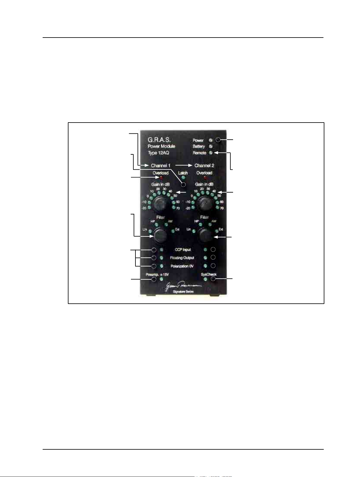
Remote LED
Can be selected only via the RS232 interface. When on, all manual switches (except the Power
button) are disabled. Control is only via the RS232 interface. Cancelled either via the RS232
interface or by switching off/on.
Latch button
When activated, Overload LED(s) will remain on after detecting an overload, even after the
overload ceases. Latched Overload LED(s) can be cancelled by pressing the Latch button
once. Press the Latch button once (double push if overloaded) to cancel Latch.
The manual user controlled overload system:
The manual-user overload system can be disabled by the command: Ovlled n.
The system will be enabled on the next power on or by the command: Ovlled y.
Note: The overload system consists of two independent systems, a manual user system and a
remote controlled system.
In non-latched mode:
When the overload detector is in the non-latched mode, the respective overload LED will follow
the overload status, unless disabled by the command: Ovlled n.
The Overload LEDs will light during an overload condition; they will turn off about one second
after the overload condition ceases. This time can be changed via the command: Ovltm m or
by Ovltm #.
In latch mode:
For each of the overload detectors, an LED indicates the actual overload condition. The over-
load LED will be turned on when an overload occurs.
Pressing the latch button while no overload-LED lights will change the mode to non latched.
Pressing the latch button while an overload-LED is turned on and no overload condition is
present will turn off the overload-LED, if an overload condition is present nothing will happen.
To skip out of latch mode during an overload condition press latch button twice within a space
of 0.5 sec.
Gain in dB
Rotary switch for increasing or decreasing the gain of the conditioning amplier of this channel.
Rotate clockwise to increase gain or anti-clockwise to decrease gain. The range of gain settings
is from – 20 to 70 in steps of 10 dB.
Filter
Rotary switch for selecting the signal response of the conditioning amplier for this channel.
There are four settings, the rst three can be selected manually via the rotary switch, these are:
Lin for linear response with a high-pass lter of 0.2 Hz.
HP for linear response with a high-pass lter of 20 Hz.
AW for an A-weighted response.
Ext for an optional built-in, customised signal-response network
(contact G.R.A.S. for further details).
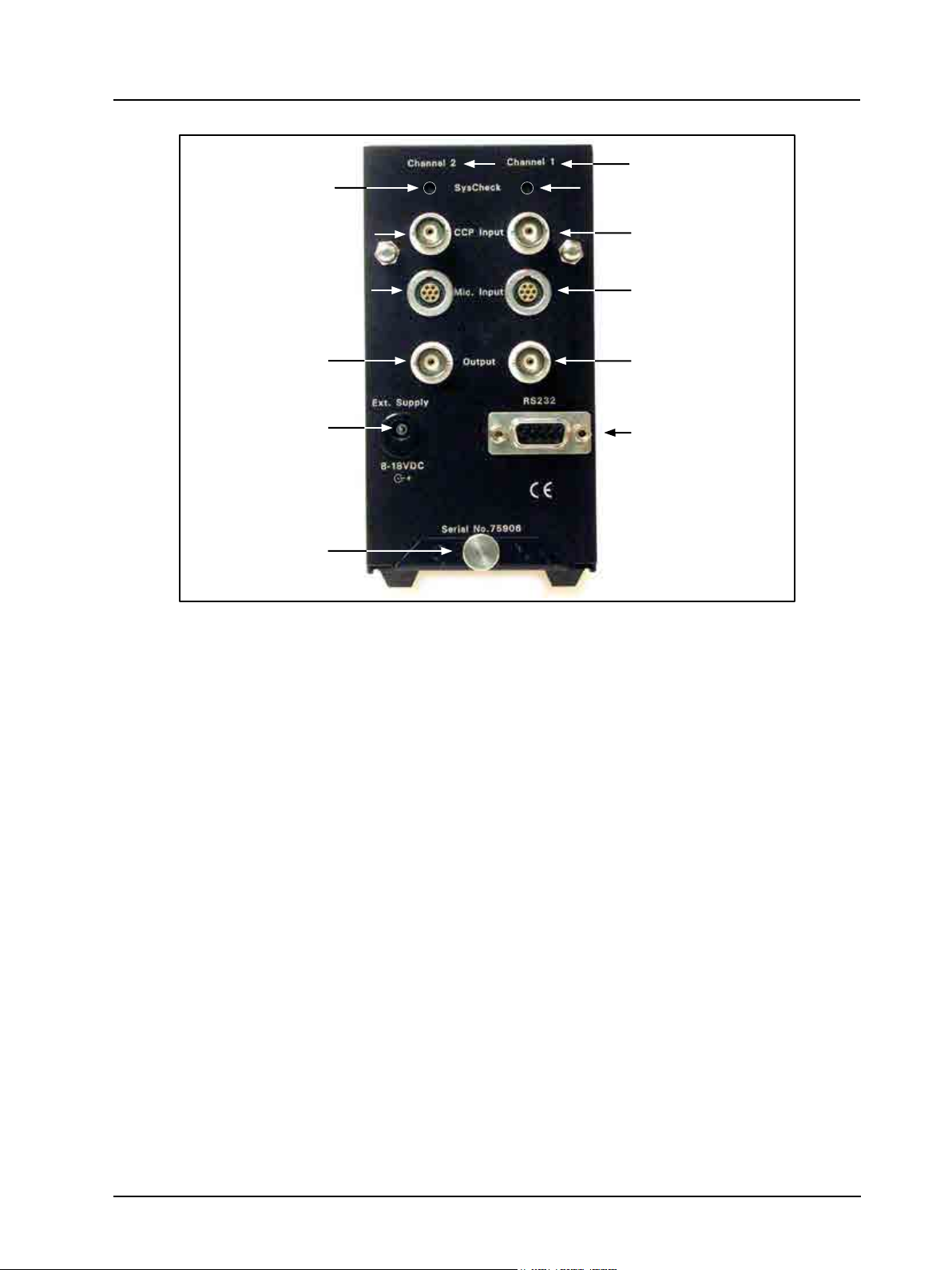
CCP Input button
When activated, the incoming signal for this channel is expected via the corresponding CCP
Input socket (BNC) on the rear panel. When cancelled, the incoming signal is expected via the
corresponding Mic Input socket (7-pin LEMO) on the rear panel.