G Sat TR-150 User manual

TR-150
Vehicle/Asset Tracker
User Manual
Version 0.2.3

TR-150 page 2
Table of Content
1. Introduction and Features............................................................................................3
1.1 Introduction ..........................................................................................................3
1.2 Features ...............................................................................................................3
2. Specifications...............................................................................................................4
2.1 Hardware.............................................................................................................. 4
3. Start-up........................................................................................................................ 5
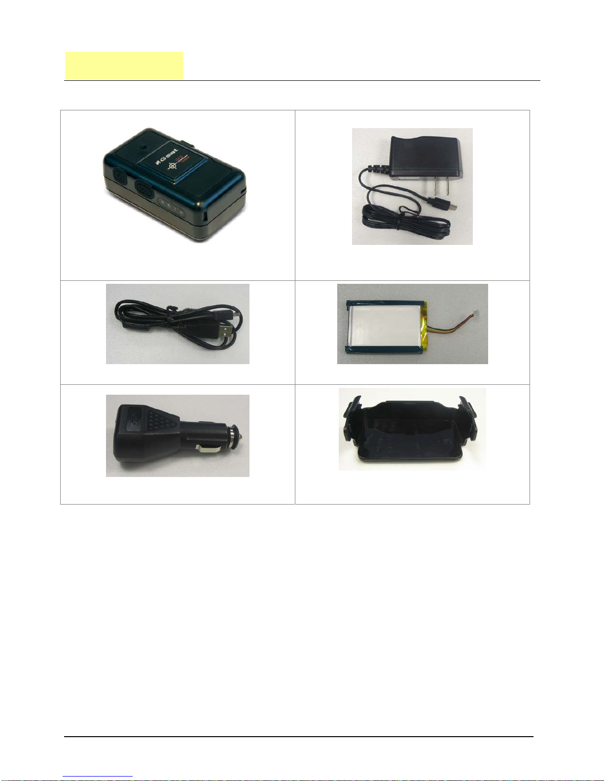
3.1 Accessories ...........................................................................................................5
3.2 Install SIM card and Battery ....................................................................................6
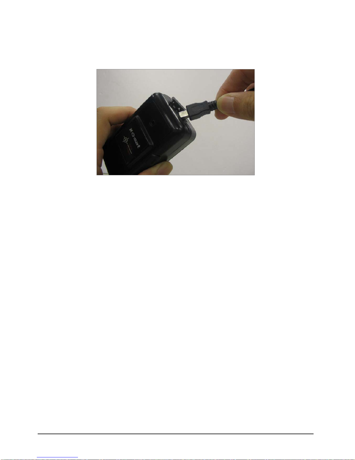
3.3 Charging the battery ..............................................................................................8
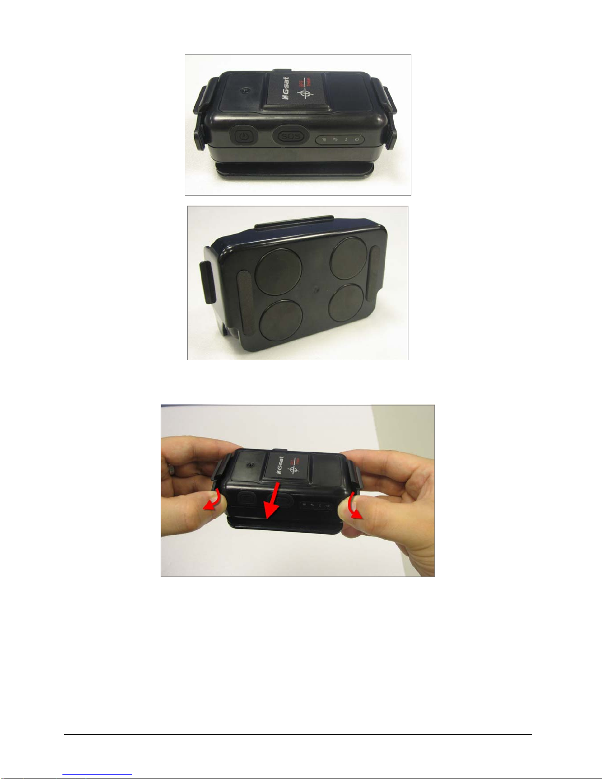
3.4 TR-150 with magnetic holder ................................................................................... 9
4. Hardware Overview.................................................................................................... 11
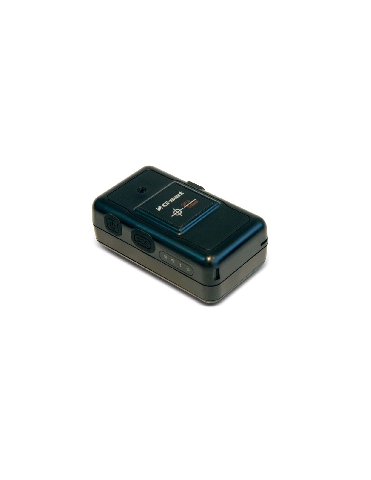
4.1 Appearance ......................................................................................................... 11
4.2 Button description................................................................................................ 12
4.3 DIP switch .......................................................................................................... 13
5. TR-150 Setup and Call Center Operation ....................................................................14
5.1 Install the USB driver ........................................................................................... 14
5.2 Install the Call Center program .............................................................................. 15
5.3 Call Center Menu ................................................................................................. 16
5.4 TR-150 Setup ...................................................................................................... 18
5.5 SMS Tracking commands and Configuration for SMS Call Center software developer ...... 20
6. Operating the device ..................................................................................................21
6.1 Turn on / Turn off................................................................................................. 21
6.2 Tracking/Monitoring TR-150 by SMS........................................................................ 22
►SMS Report functions _ Immediate Report .......................................................... 23
►SMS Report functions _ Period Report ................................................................ 24
►SMS Report functions _ Stop Report................................................................... 25
6.3 Geofence ............................................................................................................ 26
6.4 Voice monitor function .......................................................................................... 29
6.5 The format of return SMS from TR-150 ................................................................... 30
6.6 SOS function ....................................................................................................... 31
6.7 SMS Configuration ............................................................................................... 32
►SMS Configuration _ SMS Default Return Phone Number....................................... 33
►SMS Configuration _ Maximum GPS Fixing Time .................................................. 34
►SMS Configuration _ Default Report Mode Setting ................................................ 35
►SMS Configuration _ SOS Numbers .................................................................... 36
7. Appendix .................................................................................................................... 37
FCC Regulations:....................................................................................................... 37
RF Exposure Information (SAR) ................................................................................... 38

TR-150 page 3
1. Introduction and Features
1.1 Introduction
TR-150 is durable and water resistant GPS/GSM tracker. Allow a user to track his
vehicle and assets from anywhere through SMS. TR-150 is designed with high
capacity Li-ion battery for long operation time. There is one SOS button on the
TR-150 for emergency help. It is very easy to install or hide TR-150 in the car to
perform tracking. TR-150 is ideal application for vehicle tracking and
equipment/assets monitoring.
1.2 Features
zSiRF Star III LT GPS chipset, SiRF latest, flagship performance, lowest power
consumption GPS chipset.
zCombination of GPS ,GSM wireless network
zDurable and water resistant GPS tracker
zEasy to install or hide in the car to perform tracking. No external wires needed.
zIdeal application for vehicle tracking and equipment/assets monitoring
zOptional external antenna for GPS reception
zRechargeable 2100mA high capacity Li-ion battery for long operation time
zExternal DC power supply
zConfiguration can be done via SMS commands or by application software via USB
interface.SOS (emergency) button.
zVoice monitor function to monitor the sound/conversation live.
zGeofence function

TR-150 page 4
2. Specifications
2.1 Hardware
GSM module: Siemens GSM 900/1800
GPS Chipset: SiRF Star III LT chipset
Frequency: L1, 1575.42 MHz
C/A code: 1.023 MHz chip rate
Channels: 20 channel all-in-view tracking
Horizontal Position Accuracy: < 2.5 meters
Velocity Accuracy: 0.01 m/s
Tracking Sensitivity -159 dBm
Default datum: WGS-84
Hot start: 1 sec., average
Warm start: 35 sec., average
Cold start: 35 sec., average
Altitude Limit: 18,000 meters (60,000 feet) max.
Velocity Limit: 515 meters/second (1000 knots) max.
Acceleration Limit: Less than 4g
Jerk Limit: 20 m/sec3
Operating temperature: -20° to 55° C
Antenna Type: GPS patch antenna
Dimension: 86.7*48.9*32.5 mm
Battery: 2100mA rechargeable Li-ion battery
LED indicator: For Charging, GPS, GSM and Status.
Interface: Mini USB port for connecting to PC
Casing: Water resistant
GPS external antenna port: MMCX port

TR-150 page 5
3. Start-up
3.1 Accessories
TR-150
AC charger
USB Cable
Battery
Car charger
Mounting bracket with magnet
(optional)

TR-150 page 6
3.2 Install SIM card and Battery
zUse a coin or screwdriver to loosen the screw on back cover.
zLift the back cover and remove it as the direction shown.

TR-150 page 7
zSlide down the SIM card slot as the direction marked “OPEN” on it.
zSlide in the SIM card with its metal contacts facing down and the cut corner at
the top left.
zPlug the battery connector into socket. Be aware that the red wire is on the top
side when you plug in the connector.

TR-150 page 8
3.3 Charging the battery
Before you can use the TR-150, you must complete the following procedures:
1. Fully charge the battery. Before your first time using of TR-150, please connect
it with AC power adapter for battery charging under the power-off condition.
(The included battery is specially designed for TR-150. Please do not use other
type of battery; otherwise it will damage the device. If you need to change the
battery for TR-150, please contact you local dealer.)

TR-150 page 9
3.4 TR-150 with magnetic holder
zInsert the TR-150 with the Power button side facing out.
zPush TR-150 into the holder until it clicks in position.

TR-150 page 10
zOn the back of magnetic holder, there are 4 circular magnets which you can use
it for attaching TR-150 onto the metal material of vehicle or machine.
zTo remove TR-150, slightly push the both sides of holder outward, and slide out
the TR-150.

TR-150 page 11
4. Hardware Overview
4.1 Appearance
(1) Power button
(2) SOS button
(3) Indicators
(4) USB connector
(5) Microphone
(6) External antenna connector

TR-150 page 12
4.2 Button description
Power button
1. Power On: Press and hold the power button for 3-4 seconds.
The status LED will flash 2 times
2. Power Off: Press and hold the power button for 3-4
seconds. The status LED will flash 1 time.
SOS button
Presses the SOS Button, the status LED will flash 3 times to
indicate the button is activated. TR-150 will immediately send
out an emergency message along with its GPS report to 3
preset phone numbers.
Indicator
1. GSM LED:
yVoice monitoring: LED steady on.
yWhen no SIM card inserted, network search in progress,
ongoing user authentication, or network login in
progress: LED is blinking quickly (about once per
second).
yIn standby mode: LED is blinking slowly (once per 3
seconds)
2. GPS LED: The LED is steady on when it is fixing the location.
The LED will be blinking when TR-150’s location is fixed.
3. Status LED:
yWhen battery low: LED steady on.
yWhen enter setup mode: LED steady on.
yPress power button to turn on: LED will flash 2 times.
yPress power button to turn off: LED will flash 1 times.
yWhen SOS button is pressed: LED will flash 3 times.
yWhen encounter error: LED will flash 5 times.
4. Power LED: The LED will be orange when charger is plugged
for charging the battery. When the battery is been fully
charged, the LED goes off.

TR-150 page 13
USB connector
Connecting TR-150 to PC by a Mini USB cable, you can setup all
its features and functions from application software in PC.
You can also plug in USB cable for charging the battery.
Microphone
For voice monitoring use.
External
antenna
connector
For you to connect a MMCX external GPS antenna.
4.3 DIP switch
Note: The Factory default of DIP switch is set to OFF.
Switch 1 sets to ON: Enable the Auto-On feature. When external power is connected,
the device will auto-on. When remove external power, the device is off.
Switch 2 sets to ON: All LEDs (except Status LED) go off to perform secret tracking.
Status LED flashes as usual except battery low. (In another word, Status LED is not
on if battery is low.)
Switch 3 sets to ON: For entering setting mode.
Switch 4: Reserved for future use.

TR-150 page 14
5. TR-150 Setup and Call Center
Operation
5.1 Install the USB driver
1.) Insert the Driver CD into your CD-ROM driver.
2.) AutoRun installation window will appear.
3.) Click “Install USB Driver” button to install the USB driver.
4.) You will see two folders. If your Windows is Vista version, please double click to
open “PL2303_USB_Driver_for_Windows_Vista” folder and double click
on “PL-2303 Vista Driver Installer.exe” to begin installation. Follow the
instruction to complete the installation process.
5.) If your Windows is XP or 2000 version, please double click to open
“PL2303_USB_Driver_for_Windows_2000_XP” folder and double click on
“PL-2303 Driver Installer.exe” to begin installation. Follow the instruction to
complete the installation process.

TR-150 page 15
5.2 Install the Call Center program
1.) Click “Install PC Software” button to install the Call Center program.
2.) Follow the instruction to complete the installation process.
3.) After the installation is completed. You will see the icon “TR150-Call Center”
appears on desktop. Double click on this icon to start TR150 Call Center
program.

TR-150 page 16
5.3 Call Center Menu

TR-150 page 17
Menu item Description
File > Exit Close the Call Center program.
Management > User
Information
Display the User Information. You can setup up to 5 users in the Call
Center.
Management > User Edit For deleting a user. The Call Center can only hold 5 users’ information
at most. If you want to add a new user after you have already set 5
users, please delete an existing one first.
Device > TR150 Setup
When a TR-150 is connected to your PC, you can do the basic setup for
TR-150.
Map > View Tracking Points
Check this item to mark returned location in the Google Map.
When you receive the latest data report from TR-150, it will
automatically update the point on Google Map.
(Only for SMS Tracking function.)
Map > Export KML File
Export information to the KML Format.
(Only for SMS Tracking function.)
About Version information.
Delete user.

TR-150 page 18
5.4 TR-150 Setup
1.) Connect the USB cable to TR-150 and the USB port on your PC.
2.) Set DIP Switch 3 to “On” position.
3.) Turn on the power of TR-150. The status LED will light on red indicating it has
already entered the setup mode.
4.) Start Call Center program.
5.) Click Device > TR150 Setup to select the COM port. If you are not sure about
which COM port to use, please click “Scan COM Port” button to automatically
scan it. Then click “Setup” button to enter setup window.

TR-150 page 19
Information: the basic information of TR-150
Item Description
Firmware Version Firmware version of TR-150
Module IMEI International Mobile Equipment Identity
Set Time Zone
On: The SMS returned by TR-150 will contain a local time.
Off: The SMS returned by TR-150 will contain a Coordinated Universal
Time, abbreviated UTC.
User Name Input a user name here.
Phone Number Input the phone number of this TR-150.
SMS Default Return Phone Number
Item Description
SMS Default Return
Phone Number
TR-150 will send data report or confirmed message back to this return
phone number that is in the last field of all SMS tracking commands.
If user leaves “Return Phone Number” empty in the tracking commands,
TR-150 will send report back to “SMS Default Return Phone Number”.
If “Return Phone Number” and “SMS Default Return Phone Number”
are both empty, TR will send report back to caller ID.
Maximum GPS Tracking Time
Item Description
Maximum GPS Fixing
Time
The time that allows for GPS fixing. If GPS fixing is not achieved in time, it
will close GPS and send back the previous location info.
Default Report Mode Setting
Item Description
Default Report Mode
User can configure TR-150 to perform the “Default Report Mode”.
There are 3 report modes: immediate report, period report, stop report
(standby). When you select some report mode, the unavailable item will be
disabled.
After power on the device, TR-150 will perform the “Default Report Mode”
automatically. For example, if the default report mode is set to “Period
Report” mode, every time when user power on the TR-150, it will send out
period reports by default.
Report Interval Time interval of sending data report for period report mode.
The unit is second.
Report Format Set TR-150 to return message by Format0 or Format1. (Please see
description later in this user manual.)
Number of Reports Set how many reports will be sent for period report mode?
Return Phone Number
for Default Report
Mode
After turn on the TR-150, it will perform default report mode and send the
data report to this number.
SOS Number
Item Description
SOS Number When SOS button is pressed, TR-150 will dial to these 3 numbers and
send the location information to them by SMS.

TR-150 page 20
OK OK to confirm and save.
Reset Default Reset system to Factory Default.
Cancel Cancel the Setup.
5.5 SMS Tracking commands and Configuration for SMS
Call Center software developer
You can connect one TR-150 to PC and use GlobalSat PC software Call Center to send
SMS tracking commands and SMS configurations to control TR-150. It can help Call
Center service providers to evaluate TR-150 and build their own SMS Call Center
efficiently.
Please refer to “SMS_Call_Center_software_Development_manual_VX.X_EN.doc”
for details.
Table of contents
Other G Sat GPS manuals