G Sat TR-151A User manual

TR-151A / TR-151E
Vehicle/Asset Tracker
User Manual
Version 0.9.9

TR-151 page 2
Table of Content
1. Introduction and Features..............................................................................................3
1.1 Introduction............................................................................................................3
1.2 Features .................................................................................................................3
1.3 Hardware................................................................................................................4
2. Start-up..........................................................................................................................5
2.1 Accessories .............................................................................................................5
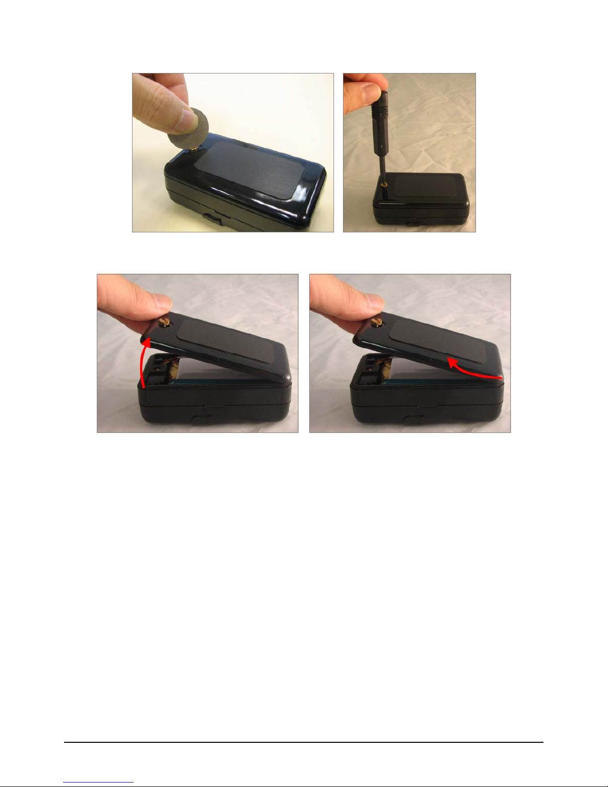
2.2 Install SIM card and Battery ......................................................................................6
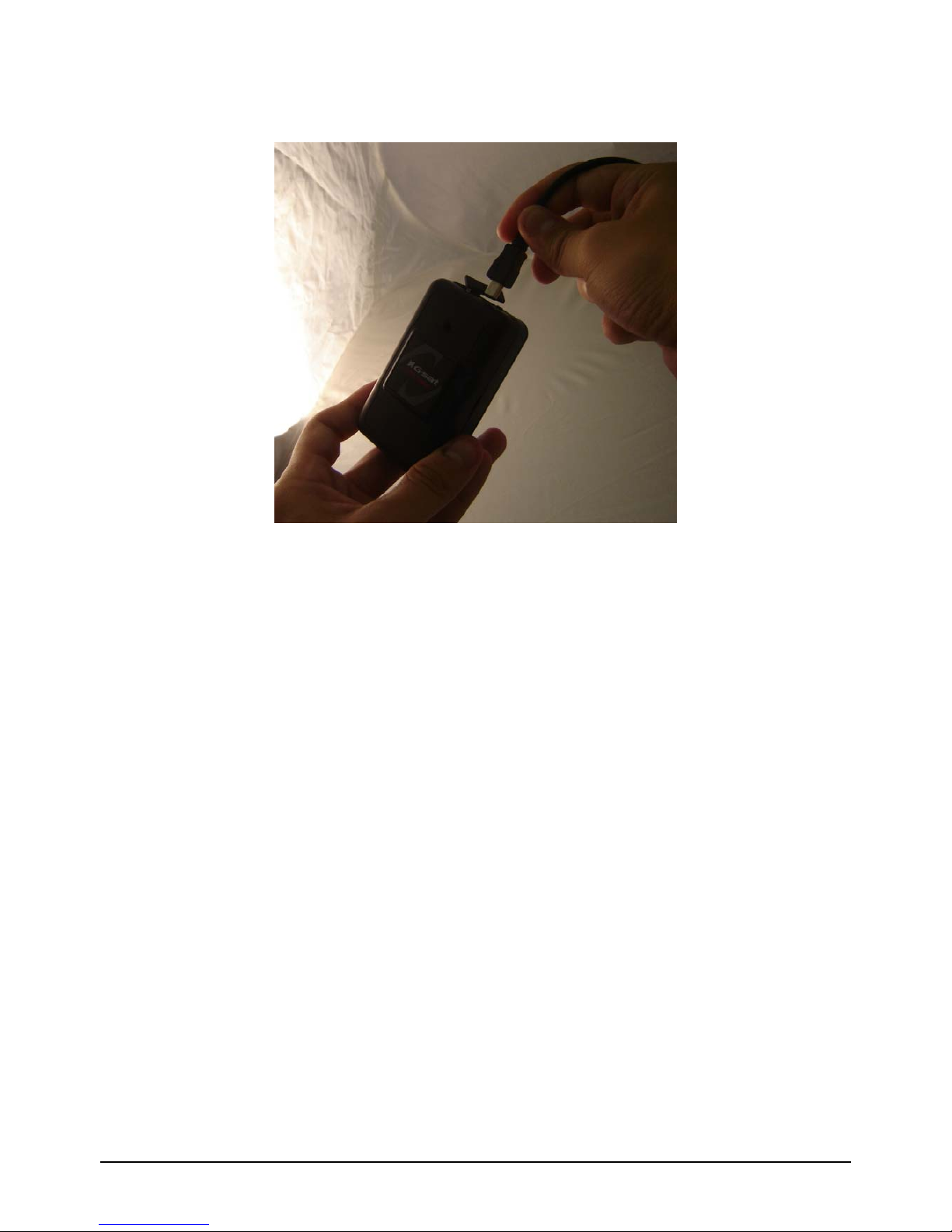
2.3 Charging the battery ................................................................................................9
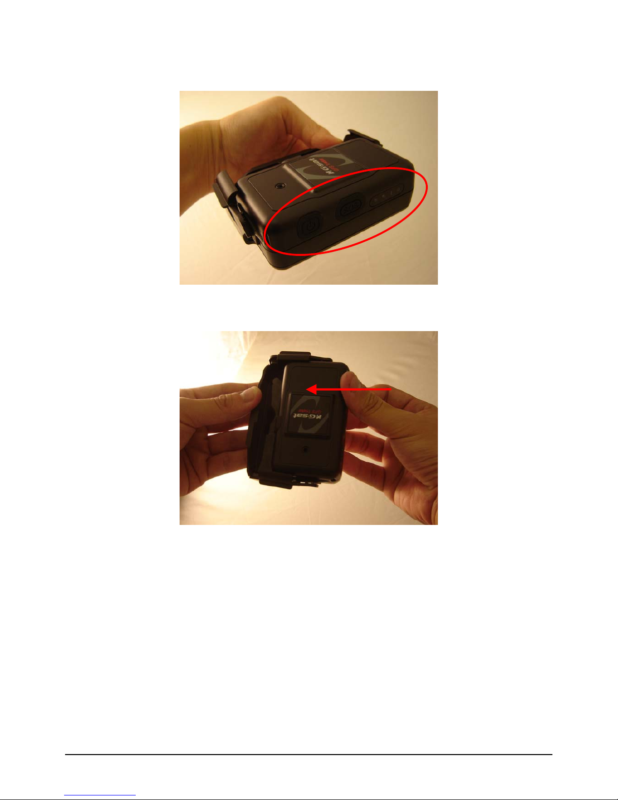
2.4 TR-151 with magnetic holder...................................................................................10
2.5 Turn on/off the device.............................................................................................12
2.6 Button Description .................................................................................................12
2.7 DIP switch ............................................................................................................15
3. TR-151 Setup and Call Center Operation ......................................................................16
3.1 Install the USB driver .............................................................................................16
3.2 Install the Call Center program ................................................................................17
3.3 Call Center Operation .............................................................................................18
3.3.1 Set TR-151 by call center for the first time. ......................................................18
3.3.2 View the IMEI code and phone number of TR-151 device....................................20
3.3.3 Delete a user (TR-151 device) from Call center .................................................21
3.4 Description of the Call Center UI ..............................................................................22
3.5 SMS Tracking commands and Configuration for SMS Call Center software developer ........26
4. Operating the TR-151................................................................................................... 27
4.1 How to set SOS number of TR-151?..........................................................................27
4.2 How to set TR-151 to immediately report its position by SMS?......................................28
4.3 How to set TR-151 to periodically report its position by SMS? .......................................29
4.4 How to set TR-151 to immediately report its position by GPRS? ....................................30
4.5 How to set TR-151 to periodically report its position by GPRS?......................................31
4.6 Tracking/Monitoring TR-151 by GPRS ........................................................................32
4.7 Displaying the location on map ................................................................................33
4.8 How to set TR-151 enter Geofence mode? .................................................................35
4.9 How to make TR-151 do Voice monitor function? ........................................................38
4.10. How to set TR-151 enter Parking Mode? .................................................................39
4.11 How to set TR-151 enter Sleeping Mode?.................................................................40
4.12 The return format from TR-151 ..............................................................................41
4.13 SMS Configuration................................................................................................43
4.13.1 SMS Configuration _ SMS Default Return Phone Number...................................45
4.13.2 SMS Configuration _ Maximum GPS Fixing Time..............................................46
4.13.3 SMS Configuration _ Default Report Mode Setting............................................47
4.13.4 SMS Configuration _ GPRS Setting ................................................................48

TR-151 page 3
1. Introduction and Features
1.1 Introduction
TR-151 is a durable and water resistant GPS/GSM/GPRS tracker. Users can install TR-151 on
vehicles or assets for tracking. It can send out SMS with its location (longitude and latitude) to
user’s cell phone by GSM network or to personal computer by internet connection of GPRS
network. Then users can track the location of their vehicles or assets. TR-151 is designed to
equip with high capacity of Li-ion battery for long operation time. There is one SOS button on the
TR-151 for emergency help. It is very easy to install or hide TR-151 in the car to perform tracking.
TR-151 is ideal application for vehicle tracking and equipment/assets monitoring.
1.2 Features
zHigh sensitive GPS chipset
zCombination of GPS ,GSM/GPRS wireless network
zDurable and water resistant GPS tracker
zEasy to install or hide in the car to perform tracking. No external wires needed.
zIdeal application for vehicle tracking and equipment/assets monitoring
zOptional external antenna for GPS reception
zRechargeable 2100mA high capacity Li-ion battery for long operation time
zExternal DC power supply
zConfiguration can be done via SMS commands or by application software via USB interface.
zSOS (emergency) button.
zVoice monitor function to monitor the sound/conversation live.
zGeofence function
NOTE: Voice Monitoring function allows user to send a SMS with voice monitoring command by a cellular phone
to TR-151. TR-151 will call back to the returned number in the SMS. And then user can listen to the sound or voice
around TR-151. While users listen to the sounds or voice around TR-151, people who around TR-151 won’t know
they are under voice monitoring. Please refer to page29 to get the detailed method of making voice monitoring.
NOTE: Geofence feature allows user to set up to 10 permissible or restricted areas whose shape is either circular
or rectangular for tracking the vehicles or monitoring the equipment/assets. Users can choose to receive alarm
message if TR-151 enters the restricted areas or to receive alarm message if TR-151 gets out the permissible
areas. Please refer to page 26-28 to get the detailed setting method of Geofence.

TR-151 page 4
1.3 Hardware GSM module: TR-151A: Siemens GSM 850/1800/1900
TR-151E: Siemens GSM 900/1800/1900
Operating temperature: -20° to 55° C
Antenna Type: GPS patch antenna
Dimension: 86.7*48.9*32.5 mm
Battery: 2100mA rechargeable Li-ion battery
LED indicator: For Charging, GPS, GSM and Status.
Interface: Mini USB port for connecting to PC
Casing: Water resistant (IPX4)
GPS external antenna port: MMCX port

TR-151 page 5
2. Start-up
2.1 Accessories
TR-151
AC charger
USB Cable
Battery
Mounting bracket with magnet (optional)

TR-151 page 6
2.2 Install SIM card and Battery
zUse a coin or screwdriver to loosen the screw on back cover.
zLift up the back cover and remove it as the direction shown.

TR-151 page 7
zPush forward the cover of SIM card slot to the position marked with “OPEN”. Then lift up
the cover.
zInsert the SIM card with its metal contacts facing down and the cut corner at the top left.
Note: It is suggested to disable the SIM PIN protection function (asks SIM PIN entry while turn
on the device) by your cellular phone before installing the SIM card in TR-151
zPlug the battery connector into socket. Be aware that the red wire must be plugged on the
top side.

TR-151 page 8
zPlease put the connector wire under the battery, and then put the battery into battery
compartment.
NOTE: After installing the battery, the status LED will emit red light. After the LED go out, please
wait for 5 seconds before turning on the power.
NOTE: Please take out the battery if you do not use TR-151 for a long time.

TR-151 page 9
2.3 Charging the battery
Before using TR-151 for the first time, please fully charge it by connecting to AC power adapter
under the power-off condition. (The attached battery is specially designed for TR-151. Please do
not use other type of battery; otherwise it will damage the device. If you need to change the
battery of TR-151, please contact your local dealer.) You can also charge the TR-151 by connect
it to PC or Notebook via USB cable. (The power of PC or of notebook should be turned on.)

TR-151 page 10
2.4 TR-151 with magnetic holder
zInsert the TR-151 with the Power button side facing out.
zPush TR-151 into the holder until it clicks in position.

TR-151 page 11
zThere are 4 circular magnets on back of the magnetic holder for attaching TR-151 onto the
metal material of vehicle or machine.
zTo remove TR-151, slightly push outward the two sides of holder, and slide out the TR-151.

TR-151 page 12
2.5 Turn on/off the device
●Turn on: After installing the battery, the status LED will emit red light. After the LED go out,
please wait for 5 seconds before turning on the power. Press the power button for 3~4
seconds. When the device is turned on, GPS will do cold start to get fixed its position for
the first time with the green GPS LED on. If location is fixed, the LED will blink. It is
suggested that you stay at outdoor places or near the window where TR-151 can receive
the better GPS signal when you turn on the device.
NOTICE: If it does not successfully get the location fixed after turning the power on,
TR-151 may be located in the weak signal area or on the move.
●Turn off: Press the Power button for 3~4 seconds. When the power is turned off, LED will
go out.
2.6 Button Description

TR-151 page 13
Power button
1. Power On: Press and hold the power button for 3-4 seconds. The
status LED will flash 2 times
2. Power Off: Press and hold the power button for 3-4 seconds. The
status LED will flash 1 time.
3. Enter parking mode: Press the power button once to enter parking
mode. When power button is pressed, LED will flash slowly (once
per second) first, and then enter parking mode. The flash number is
the second number you set in Park_Time.
SOS button
Press the SOS Button, the status LED will flash 3 times to indicate the
button is activated. TR-151 will immediately send out emergency
messages along with its GPS report to 3 preset phone numbers.
Indicator
1. GSM LED:
yVoice monitoring: LED keeps on.
yWhen no SIM card is inserted, network searches in progress,
ongoing user authentication, or network login in progress: LED
blinks quickly (about once per second).
yIn standby mode: LED blinks slowly (once for 3 seconds)
2. GPS LED: The LED keeps on when it is fixing the location. The LED
blinks when TR-151’s location has been fixed. When GPS function
is disabled, GPS LED will be off.
3. Status LED:
yWhen battery low: LED keeps on.
yWhen enter setup mode: LED keeps on.
yPress power button to turn on: LED flashes quickly 2 times.
yPress power button to turn off: LED flashes quickly 1 time.
yWhen SOS button is pressed: LED flashes slowly 3 times.
yWhen error occurs: LED flashes quickly 5 times.
yParking mode: When power button is pressed, LED will flash
slowly (once per second) first, and then enter parking mode. The
flash number is the second number you set in Park_Time. If you
want to stop parking mode, press the power button again. The LED
flashes quickly 3 times and it will exit parking mode.
ySleeping mode: LED will flash slowly 60 times and then it enters
sleeping mode.
4. Power LED:
yThe LED emits orange light when charger is plugged for charging
the battery.
yThe LED goes off after the battery has been fully charged.

TR-151 page 14
USB connector
There are two functions of the USB connector:
1. Connect TR-151 to PC by a Mini USB cable and setup all its
features and functions from application software through PC.
2. Charge the battery by connecting a USB cable.
Microphone For voice monitoring use.
External antenna
connector
For you to connect a MMCX external GPS antenna.

TR-151 page 15
2.7 DIP switch
On Off
Switch 1 Enable TR-151 to automatically power
on when it is connected to external
power.
Users have to press the power button
to power on TR-151 whether external
power is connected or not.
Switch 2 All LED works as user mode. Make all LED except status LED go off
for secret tracking. Status LED works
as user mode.
Switch 3 Setting Mode (Status LED keeps
emitting red light)
User Mode
Switch 4 Sleeping Mode User Mode
Note: You can set the switch by a little tweezers or pen point or toothpick.

TR-151 page 16
3. TR-151 Setup and Call Center
Operation
3.1 Install the USB driver
1.) Insert the Driver CD into your CD-ROM driver.
2.) AutoRun installation window will appear.
3.) Click “Install USB Driver” button to install the USB driver.
4.) You will see two folders. If your Windows is Vista version, please double click to open
“PL2303_USB_Driver_for_Windows_Vista” folder and double click on “PL-2303 Vista
Driver Installer.exe” to begin installation. Follow the instruction to complete the installation
process.
5.) If your Windows is XP or 2000 version, please double click to open
“PL2303_USB_Driver_for_Windows_2000_XP” folder and double click on “PL-2303
Driver Installer.exe” to begin installation. Follow the instruction to complete the installation
process.

TR-151 page 17
3.2 Install the Call Center program
1.) Click “Install PC Software” button to install the Call Center program.
2.) Follow the instruction to complete the installation process.
3.) After the installation is completed, you will see the icon “TR151-Call Center” appears on
desktop. Double click on this icon to start TR151 Call Center program.
TR-151 Call
Center

TR-151 page 18
3.3 Call Center Operation
3.3.1 Set TR-151 by call center for the first time.
1. Make TR-151 enter setting mode by setting DIP switch 3 to the “ON” position.
2. Connect TR-151 and PC by the USB cable.
3. Turn on the power of TR-151. (The status LED will emit red light showing it is under setting
mode.)
4. Start call center.
5. Click DeviceÆTR151 Setup. Or click .Then the window below will be brought up.

TR-151 page 19
6. If you do not know TR-151 which COM port is connected to, please click “Scan COM Port”
button to automatically scan it. Then click “Setup” button to enter setup window.
7. Then the window below will be brought up.
8. Write down the IMEI code.
9. Enter a name for TR-151 device in the field of User Name. Enter the phone number of SIM
card installed in TR-151 in the field of Phone Number. Enter the three phone numbers of
emergency help in the field of SOS Number 1~SOS Number3. (ESSENTIAL)
10. Check “SMS Default Return Phone Number” and enter a phone number for receiving
confirmed message or data report. (OPTIONAL)
11. Select the time for GPS fixing in the pull-down menu of Maximum GPS Fixing Time. The
unit is minute. If GPS fixing is not achieved within time, it will close GPS and send back the
previous location info. (OPTIONAL)
12. Select a report mode (Stop Report, Immediate Report, and Period Report) for Default
Report Mode and enter the concerning parameters. (OPTIONAL)
13. Park Mode Setting: Set the time length between entering Parking Mode after pressing the
power button under power on condition in the field of Park Time. Set the interval of sending
Park mode reporting SMS in the field of Park Interval. Set how many Park mode reporting
SMS will be sent in the field of Park Number of Reports. Enter the phone number for
receiving Park mode reporting SMS in the field of Park Return Phone Number.
14. Sleep Moe Setting: Set the time length of Sleep mode in the field of Sleep Time. Set the

TR-151 page 20
interval of sending Sleep mode reporting SMS in the field of Sleep Interval. Set how many
Park mode reporting SMS will be sent in the field of Sleep Number of Reports. Enter the
phone number for receiving Park mode reporting SMS in the field of Sleep Return Phone
Number.
15. GPRS Setting: Set the GPRS concerning parameters. For the GPRS setting, please consult
with your GPRS network service provider. (NOTE: GPRS Server Host Name must be a
physical IP of the installed TR-151 call center’s PC)
16. Click OK to save the setting and then unplug the USB cable from PC and TR-151.
17. Press power button to turn off TR-151.
18. Remember to make TR-151 exit from setting mode by setting DIP Switch 3 to “OFF”
position.
3.3.2 View the IMEI code and phone number of TR-151 device
Users can view the IMEI code and phone number of TR-151 that has been made basic setup by
management center.
Click Management ÆUser Information. Or click . Then the window below will be
brought up.
Other manuals for TR-151A
1
This manual suits for next models
1
Table of contents
Other G Sat GPS manuals