GAI-Tronics LE100-FSR User manual

Pub. 42004-665L2C
GAI-Tronics Corporation P.O. Box 1060, Reading, PA 19607-1060 USA
610-777-1374 n800-492-1212 nFax: 610-775-6540
GAI-TRONICS CORPORATION
Model LE100-FSR and LE100-FLR
Page/Party®Line Extender
Confidentiality Notice
This manual is provided solely as an operational, installation, and maintenance guide and contains
sensitive business and technical information which is confidential and proprietary to GAI-Tronics.
GAI-Tronics retains all intellectual property and other rights in or to the information contained herein,
and such information may only be used in connection with the operation of your GAI-Tronics product or
system. This manual may not be disclosed in any form, in whole or in part, directly or indirectly, to any
third party.
General Information
The Models LE100-FSR and LE100-FLR are used in pairs to extend a SmartSeriesor a conventional
Page/Party® systems over fiber optic cable. Two segments of Page/Party® system cables can be
connected using a fiber optic cable containing two fibers. The distance between the two system cables
and the type of fiber optic cable available must be considered when choosing the line extender model to
be used.
•Model LE100-FSR operates with multi-mode fiber optic cable (62/125 um) and can be used to
connect system cables up to 6.7 km (4.2 miles) apart. This distance is based on a signal loss of
3db/km.
•The Model LE100-FLR operates with single-mode fiber optic cable (9/125 um) and can be used to
connect system cables up to 82 km (51 miles). This distance is based on signal loss of .35 db/km.
Figure 1shows a typical application using two Line Extenders to connect segments of a Page/Party®
system. As noted above, the units can be separated by as much as 51 miles depending on the line
extender and the type of fiber optic cable used. The fiber optic cable is also beneficial in environments
where electrical interference (such as EMI, RFI, spikes, and differential ground loops) is a problem or
where security is critical.
Model
LE100
(master)
Model
LE100
(slave)
Data Link
System Cable “A”System Cable “B”
Aux
Inputs Aux
Inputs
Indicator,
Monitor,
and Aux
Outputs
Indicator,
Monitor,
and Aux
Outputs
Field
Devices Field
Devices
Figure 1. System Extension Application

Pub. 42004-665L2C
Page/Party® Line Extender Page: 2of 18
f:\standard ioms - current release\instr. manuals (42004)\42004-665l2c effective 4-10.doc
03/01
Each line extender provides the following connections to the Page/Party®system and external I/O devices.
•page line
•1-5 party lines
•page line audio detector output
•page line ground-fault detector output
•page line monitor output
•5 auxiliary inputs
•5 corresponding auxiliary contact closure outputs
Technical Information
There is no continuity (no dc path) between the system cables attached to the Line Extender on the
opposite ends of a data link, so the line extenders must convey all audio signals, line conditions, and
input/output device status across the data link in digital form. It uses T1 carrier technology to digitize the
audio signals present on its system cable and time-division multiplex (combine) them with additional data
such as the state of its auxiliary inputs. The Line Extender transmits the 1.544 Mbps time-division
multiplexed data stream over a full-duplex, point-to-point data link to its companion unit.
In general, when a Line Extender detects a condition on its associated system cable, it causes that same
condition to appear on the corresponding system cable attached to its companion unit. For example, if it
detects an off-hook condition on a party line, it causes the companion unit to simulate an off-hook
condition at its corresponding party line interface. However, page line ground-fault detection is isolated
to the effected Line Extender. The fault condition is not recreated and the ground fault detector output is
not activated on the companion unit.
An auxiliary input controls only the corresponding auxiliary output on the companion unit. It does not
affect any auxiliary outputs on the same unit.
CAUTION
•Each Line Extender requires a local earth ground.
•Although the Line Extender data link interface uses T1 carrier technology, it does not comply
with telephone network standards such as ANSI T1.403. Do not use the Line Extender with
external T1 lines connected to a telephone network.
NOTE
•The Line Extender is designed for a point-to-point data link connection to a companion Line
Extender. No other data link configurations are supported.
•The Line Extender does not support simultaneous FSK data communication and Volume Level
Control (VLC). These two features are incompatible with each other and may not coexist
within the same system.
CABLE TERMINATIONS
The Line Extender provides screw-type terminals for connecting the Page/Party® system cables and any
input/output cables that may be used. The terminal blocks support a wire size range of 24 AWG to
12 AWG. The following table summarizes the available connections and the terminal designations.

Pub. 42004-665L2C
Page/Party® Line Extender Page: 3of 18
f:\standard ioms - current release\instr. manuals (42004)\42004-665l2c effective 4-10.doc
03/01
Terminal Designator Description
Page/Party® System Cable
TB3-4, TB4-4 PAGE L1 Page line (L1)
TB3-5, TB4-5 PAGE L2 Page line (L2)
TB3-6, TB4-6 PL1 L1 Party line 1 (L1)
TB3-7, TB4-7 PL1 L2 Party line 1 (L2)
TB3-8, TB4-8 PL2 L1 Party line 2 (L1)
TB3-9, TB4-9 PL2 L2 Party line 2 (L2)
TB3-10, TB4-10 PL3 L1 Party line 3 (L1)
TB3-11, TB4-11 PL3 L2 Party line 3 (L2)
TB3-12, TB4-12 PL4 L1 Party line 4 (L1)
TB3-13, TB4-13 PL4 L2 Party line 4 (L2)
TB3-14, TB4-14 PL5 L1 Party line 5 (L1)
TB3-15, TB4-15 PL5 L2 Party line 5 (L2)
TB3-1, TB4-1 120V 50-60Hz AC hot
TB3-2, TB4-2 Neutral AC neutral
TB3-3, TB4-3 Ground Earth ground
TB3-16, TB4-16 Spare Spare
Page Line Audio Detector Output
TB1-21 PG AUD OUT + Page line audio detector output (+)
TB1-22 PG AUD OUT - Page line audio detector output (-)
Page Line Ground-Fault Detector Output
TB1-23 PG GF OUT + Page line ground-fault detector output (+)
TB1-24 PG GF OUT - Page line ground-fault detector output (-)
Page Line Monitor Output
TB1-29 PG MON L1 Page line monitor output (L1)
TB1-30 PG MON L2 Page line monitor output (L2)
Auxiliary Inputs
TB1-1 AUX 1 IN + Auxiliary input 1 (+)
TB1-2 AUX 1 IN - Auxiliary input 1 (-)
TB1-3 AUX 2 IN + Auxiliary input 2 (+)
TB1-4 AUX 2 IN - Auxiliary input 2 (-)
TB1-5 AUX 3 IN + Auxiliary input 3 (+)
TB1-6 AUX 3 IN - Auxiliary input 3 (-)
TB1-7 AUX 4 IN + Auxiliary input 4 (+)
TB1-8 AUX 4 IN - Auxiliary input 4 (-)
TB1-9 AUX 5 IN + Auxiliary input 5 (+)
TB1-10 AUX 5 IN - Auxiliary input 5 (-)

Pub. 42004-665L2C
Page/Party® Line Extender Page: 4of 18
f:\standard ioms - current release\instr. manuals (42004)\42004-665l2c effective 4-10.doc
03/01
Terminal Designator Description
Auxiliary Outputs
TB1-11 AUX 1 OUT + Auxiliary output 1 (+)
TB1-12 AUX 1 OUT - Auxiliary output 1 (-)
TB1-13 AUX 2 OUT + Auxiliary output 2 (+)
TB1-14 AUX 2 OUT - Auxiliary output 2 (-)
TB1-15 AUX 3 OUT + Auxiliary output 3 (+)
TB1-16 AUX 3 OUT - Auxiliary output 3 (-)
TB1-17 AUX 4 OUT + Auxiliary output 4 (+)
TB1-18 AUX 4 OUT - Auxiliary output 4 (-)
TB1-19 AUX 5 OUT + Auxiliary output 5 (+)
TB1-20 AUX 5 OUT - Auxiliary output 5 (-)
Page/Party®System Cable
The Line Extender provides two sets of 16 screw terminal connection points for the Page/Party®system
cable. In most applications, only one set is used to connect the system cable. However, a second set is
provided to allow daisy chaining of the system cable if desired.
Fiber Optic Cable
The Line Extender provides a pair of ST fiber optic connectors (one for the transmit fiber and one for the
receive fiber). Typical connections for this method are shown in Figure 2.
CABLES
FIBER OPTIC
(SLAVE)(MASTER)
MODEL LE100-FxR MODEL LE100-FxR
RX
TX
OPTIC
FIBER
TRANSCEIVER TRANSCEIVER
FIBER
OPTIC
TX
RX
Figure 2. Fiber Optic Data Link Connection

Pub. 42004-665L2C
Page/Party® Line Extender Page: 5of 18
f:\standard ioms - current release\instr. manuals (42004)\42004-665l2c effective 4-10.doc
03/01
Page Line Audio Detector Output
The Page Line Audio Detector indicating output activates in response to the presence of audio on the
page line and is typically used to control an external dc-coil relay. Its polarity-sensitive, single-pole
single-throw (SPST) solid-state relay contacts are rated at 200 mA and can switch 0 to 28 V dc. A typical
application of this output is shown in Figure 3.
+
+
EQUIVALENT
OR
1N4007
COIL
RELAY
0 TO 28 VDC
OUTPUT -
OUTPUT +
Model LE100
-
Figure 3. Output Application
Page Line Ground-Fault Detector Output
A ground fault occurs when one conductor of the page line is shorted to earth ground. This condition
generally causes noise (buzz or hum) to be inducted onto the page line and broadcast from the speakers.
The Line Extender is capable of detecting a ground fault and activating an output. The output will
activate if less than 5,000 ohms of resistance is measured from either conductor of the side of the page
line to ground. The output is typically used to control an external dc-coil relay. Its polarity-sensitive,
SPST solid-state relay contacts are rated at 200 mA and can switch 0 to 28 V dc.
Note that the page line ground-fault detector output only responds to ground-faults occurring on the page
line of its corresponding system cable. A typical application of this output is shown in Figure 3.
Page Line Monitor Output
This audio output monitors the audio present on the page line. It provides a balanced output capable of
driving 0.775 Vrms into a 600-ohm load at 1 kHz and is typically used to drive the input of a central
amplifier.
Auxiliary Inputs
The Line Extender provides connection points for external inputs, either normally open (N.O.) or
normally closed (N.C.) voltage-free contacts. Each input activates with a minimum closure duration of
50 ms. The activating contact closure can be located up to one mile from the Line Extender using
24 AWG wire or larger. Each input controls the corresponding auxiliary outputs on the companion Line
Extender unit.

Pub. 42004-665L2C
Page/Party® Line Extender Page: 6of 18
f:\standard ioms - current release\instr. manuals (42004)\42004-665l2c effective 4-10.doc
03/01
Auxiliary Outputs
The Line Extender provides auxiliary output terminals for on/off control of external devices. Each output
is activated by the corresponding auxiliary inputs on the companion Line Extender unit. Outputs are
typically used to control external dc-coil relays. Each output consists of a SPST solid-state relay contact
rated at 200 mA and can switch 0 to 28 V dc. A typical application of these outputs is shown in Figure 3.
How to Maintain the Assembly
HARDWARE CONFIGURATION
The Line Extender includes a number of jumpers and switches that permit the unit to be configured for a
variety of applications. All jumpers and switches are located on the main printed circuit (PC) board
mounted on the inside of the front door. Refer to Figure 4for the reference numbers and locations of the
jumpers and switches on the main PC board.
Unit Configuration
Overall configuration of the unit consists of master/slave selection, operating mode selection, and test
tone operation.
MASTER/SLAVE SELECTION
One unit of the pair of Line Extenders must be configured as the master and the other as the slave. The
master generates the timing reference for the data link, while the slave uses this timing reference for its
own timing. In this manner, the master and slave are synchronized.
To configure the unit as either the master or the slave, use jumper J10 (Ref. 1), labeled MAS/SL, as
follows:
•To configure the unit as the master (default), short pins 1and 2.
•To configure the unit as the slave, short pins 2and 3.
OPERATING MODE SELECTION
Normally, operation of the Line Extender is autonomous. However, under certain circumstances, it may
be necessary to manually reset the unit.
To control the operating mode of the unit, use jumper J7 (Ref. 2), labeled BRD RESET, as follows:
•For normal operation (default), short pins 1and 2.
•To reset the unit, momentarily short pins 2and 3.

Pub. 42004-665L2C
Page/Party® Line Extender Page: 7of 18
f:\standard ioms - current release\instr. manuals (42004)\42004-665l2c effective 4-10.doc
03/01
Unit Configuration
1. Master/Slave (J10, MAS/SL)
2. Operating Mode (J7, BRD RESET)
3. Test Tone (J8)
Data Link Configuration
4. Line Build Out (S1, LINE BO SEL)
2 3 1
4
LE100 Main PCBA
Figure 4. Unit Configuration and Data Link Configuration
TEST TONE OPERATION
The test tone is used to verify that the connection between the two units is functioning properly after
installation. The test tone is not used under normal operation.
To enable the test tone, short pins 2 and 3 on J8. To disable the test tone, short pins 1 and 2 on J8.
Data Link Configuration
The data link transmitter portion of the Line Extender has the ability to simulate various amounts of cable
loss (attenuation) between the main PC board and the fiber optic transceiver. Switch S1 of the Main
PCBA (Figure 4, Ref. 4), labeled LINE BO SEL, should be set to position 0 (default – 0 to 133 feet).
Note: After altering the position of S1, the main PCBA must be reset before the new setting will take
effect. Momentarily short pins 2 and 3 of J7 to reset the main PCBA.
The fiber optic transceiver also contains nine DIP switches, numbered 1 through 9, located on the front
panel. Refer to Figure 5.
87654321 9
UP(off)
Figure 5. Fiber Optic Transceiver Dip Switches
DIP SWITCH SETTINGS
DIP switches should be set as shown in the following table. Refer to the fiber optic transceiver manual
for more information on these switches as well as other features.

Pub. 42004-665L2C
Page/Party® Line Extender Page: 8of 18
f:\standard ioms - current release\instr. manuals (42004)\42004-665l2c effective 4-10.doc
03/01
Switch # Switch Function Switch Position Setting
1Line Coding UP B8ZS
2TAOS Test UP OFF
3Loop-back Test UP OFF
4Line Build Out 1 UP
5Line Build Out 2 DOWN
6Line Build Out 3 DOWN
0-133ft
7Input Impedance UP 100 Ohms
8Clock/Data Encode UP OFF
9No Function UP or DOWN N/A
LOCAL LOOP-BACK TEST SWITCH
For normal operation the Loop-back Test Switch should be in the center position (labeled OPR).
Page Line Configuration
Configuration of the page line interface consists of FSK communication configuration, page line balance
configuration, page line ground-fault detector configuration, and VLC communication configuration.
NOTE
Because there is no continuity (no dc path) between the system cables attached to the Line
Extender on the opposite ends of a data link, configuration and operation of these features for one
unit are independent of the companion unit.
FSK COMMUNICATION CONFIGURATION
If a pair of Line Extenders are installed in a system which utilizes FSK data communication, as in
SmartSeriessystems, the FSK feature must be enabled at both Line Extenders. Jumpers J1 and J2,
labeled FSK and VLC respectively, of the main PCBA control the FSK communication feature as
specified in the following table:
FSK Communication Mode J1 Setting J2 Setting
Disabled Pins 1 & 2 shorted No effect
Enabled Pins 2 & 3 shorted Pins 1 & 2 shorted
(VLC Disabled)
Notes:
•If FSK data communication is enabled, then VLC communication must be disabled.
•After altering the position of J1 or J2, the main PCBA must be reset before the new setting will take
effect. Momentarily short pins 2 and3 of J7 to reset the board.
PAGE LINE BALANCE CONFIGURATION
For optimum performance, the page and party lines must be properly loaded with a 33 ohm (nominal)
loading resistor. This is normally accomplished with a Model 305-001 Line Balance Assembly in
conventional Page/Party® systems or with a Page/Party® Interface PCBA in SmartSeriessystems. The
Line Extender also is capable of providing the necessary line loading resistance.

Pub. 42004-665L2C
Page/Party® Line Extender Page: 9of 18
f:\standard ioms - current release\instr. manuals (42004)\42004-665l2c effective 4-10.doc
03/01
Note: It is important that one and only one device be used to balance the page and party lines. For
optimum performance, the page line balance provided by the Line Extender should be used whenever
possible.
Jumper J12, labeled PG BAL, on the Main PCBA controls the page line balance configuration and
should be set as follows:
•Short pins 1 and 2 of J12 (Page Line Balance Disabled) only if the page line contains an external line
balance that can not be readily removed. Examples of this situation include:
—The page line is connected to a Page/Party® Interface PCBA
—The page line is connected to a Model 305-001 Line Balance Assembly
•Short pins 2 and 3 of J12 (Page Line Balance Enabled) in all other cases.
PAGE LINE GROUND-FAULT DETECTOR CONFIGURATION
The Line Extender contains circuitry to detect ground faults on the page line. When detected, the ground-
fault output is activated.
Jumper J13, labeled PG GND FLT DET, on the main PCBA controls the page line ground-fault detector
configuration and should be set as follows:
•To disable page line ground-fault detection (default), short pins 1and 2.
Note: Use this setting when the system cable is connected to a Page/Party® Interface PCBA in a
SmartSeriessystem because the Page/Party® Interface PCBA already contains ground fault
detection circuitry.
•To enable page line ground-fault detection, short pins 2and 3.
VLC COMMUNICATION CONFIGURATION
VLC communication used in some Page/Party® systems to provide speaker volume control or activation
of remote devices. It consists of a 50 kHz tone transmitted on the page line to receiving devices located
throughout the system. The VLC function is most commonly used with the Model TS959 Tone/Speech
Generator for speaker control and activating external devices during alarm conditions. If a pair of Line
Extenders are installed in a system which utilizes VLC, then the VLC communication feature must be
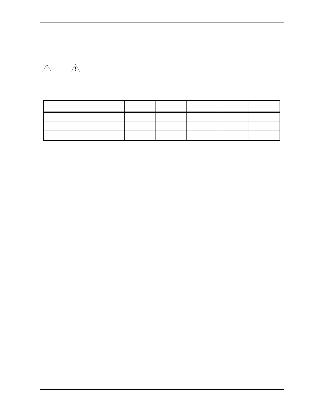
enabled at both Line Extenders. Jumpers J1 and J2, labeled FSK and VLC respectively, on the main
PCBA control the VLC communication feature as specified in the following table:
VLC Communication Mode J1 Setting J2 Setting
Disabled No effect Pins 1 & 2 shorted
Enabled Pins 1 & 2 shorted
(FSK Disabled) Pins 2 & 3 shorted
Notes:
•If VLC communication is enabled, then FSK communication must be disabled.
•The Line Extender only supports 50 kHz VLC transmission. No other VLC frequencies are
supported.
•After altering the position of J1 or J2, the main PCBA must be reset before the new setting will take
effect. Momentarily short pins 2 and 3 of J7 to reset the main PCBA.

Pub. 42004-665L2C
Page/Party® Line Extender Page: 10 of 18
f:\standard ioms - current release\instr. manuals (42004)\42004-665l2c effective 4-10.doc
03/01
Party Line Configuration
Configuration of the party lines consist of line balance selection, party line bias selection, and off-hook
detector gain selection. Each party line is configured independently with separate jumpers for each
feature. Use the table below to determine the appropriate jumpers for each party line interface.
NOTE
Because there is no continuity (no dc path) between the system cables attached to the Line
Extenders on the opposite ends of a data link, configuration and operation of these features for one
unit are independent of the companion unit.
Feature PL 1 PL 2 PL 3 PL 4 PL 5
Line Balance selection J15 J19 J23 J27 J31
Line Bias selection J14, J16 J18, J20 J22, J24 J26, J28 J30, J32
Off-hook detector gain selection J17 J21 J25 J29 J33
PARTY LINE BALANCE SELECTION
For optimum performance, the party lines must be properly loaded with a 33 ohm (nominal) loading
resistor. This is normally accomplished with a Model 305-001 Line Balance Assembly in conventional
Page/Party® systems or with a Page/Party® Interface PCBA in SmartSeriessystems. The Line
Extender is also capable of providing the necessary line loading resistance.
Note: It is important that one and only one device be used to balance the party lines. For optimum
performance, the party line balance provided by the Line Extender should be used whenever possible. If
a model 305-101 Line Balance Assembly is present in the system, it should be disconnected.
The party line balance for each party line should be configured as follows. Refer to the above table for
the appropriate reference designator for each party line interface:
•Short pins 1 and 2 of the party line balance selection jumper (Party Line Balance Disabled) only if the
party line contains an external line balance that can not be readily removed. Examples of this
situation include:
—Party lines 1-2 are connected to a Page/Party® Interface PCBA
—The party line is connected to a Model TI984 Telephone Interface
•Short pins 2 and 3 of the party line balance selection jumper (Party Line Balance Enabled) in all other
cases.
PARTY LINE BIAS SELECTION
The Line Extender is capable of detecting when a Page/Party® Handset Station is off-hook on a party
line. To accomplish this the device puts a dc bias voltage on each party line. If used with other devices
that perform off-hook detection such Page/Party® Interface PCBA in a SmartSeriessystem or a Model
TI984 Telephone Interface, this bias voltage must be disabled. Only one bias voltage source can be used
on a party line.
The party line bias selection for each party line should be configured as follows. Refer to the above table
for the appropriate reference designators for each party line interface:

Pub. 42004-665L2C
Page/Party® Line Extender Page: 11 of 18
f:\standard ioms - current release\instr. manuals (42004)\42004-665l2c effective 4-10.doc
03/01
•Short pins 1 and 2 of both party line bias selection jumpers (Party Line Bias Disabled) only if the
party line contains an external party line bias source that can not be readily removed. Examples of
this situation include:
—The party line is connected to a Page/Party® Interface PCBA (party lines 1 and 2 only)
—The party line is connected to a Model TI984 Telephone Interface
•Short pins 2 and 3 of both party line bias selection jumpers (Party Line Bias Enabled) in all other
cases.
PARTY LINE OFF-HOOK DETECTOR GAIN SELECTION
The Line Extender’s party line off-hook detector gains must be properly set depending on the
configuration of the party lines’ bias source.
The party line off-hook detector gain selection for each party line should be configured as follows. Refer
to the above table for the appropriate reference designator for each party line interface:
•Short pins 2 and 3 of the party line off-hook detector gain selection jumper (Low) if the party line
contains a Model TI984 Telephone Interface or if it is connected to a Page/Party® Interface PCBA
(party lines 1 & 2 only) in a SmartSeries™ system.
•Short pins 1 and 2 of the party line off-hook detector gain selection jumper (High) in all other cases.

Pub. 42004-665L2C
Page/Party® Line Extender Page: 12 of 18
f:\standard ioms - current release\instr. manuals (42004)\42004-665l2c effective 4-10.doc
03/01
Summary of Line Extender Main PCBA Jumpers and Switches
Reference
Designator Function Possible Settings
J1 FSK Communication
Enable/Disable Pins 1 & 2 shorted : FSK Communication Disabled*
Pins 2 & 3 shorted : FSK Communication Enabled
J2 VLC Communication
Enable/Disable Pins 1 & 2 shorted : VLC Communication Disabled*
Pins 2 & 3 shorted : VLC Communication Enabled
J3 VLC Tone Control Pins 1 & 2 shorted : VLC Tone Auto*
Pins 2 & 3 shorted : VLC Tone On
J5 Calibrate XR-2211 Pins 1 & 2 shorted : Calibration Disabled*
Pins 2 & 3 shorted : Calibration Enabled
J7 Board Reset Pins 1 & 2 shorted : Normal Operation*
Pins 2 & 3 shorted : Board Reset
J8 Test Tone Enable/Disable Pins 1 & 2 shorted : Test Tone Disabled*
Pins 2 & 3 shorted : Test Tone Enabled
J10 Master/Slave Select Pins 1 & 2 shorted : Master Selected*
Pins 2 & 3 shorted : Slave Selected
J12 Page Balance Select Pins 1 & 2 shorted : Page Balance Disabled*
Pins 2 & 3 shorted : Page Balance Enabled
J13 Page Line Ground-Fault
Detector Pins 1 & 2 shorted : Page Line Ground-Fault Detector
Disabled*
Pins 2 & 3 shorted : Page Line Ground-Fault Detector
Enabled
J14 & J16 Party Line 1 Bias Select Pins 1 & 2 shorted : Party Line 1 Bias Disabled*
Pins 2 & 3 shorted : Party Line 1 Bias Enabled
J15 Party Line 1 Balance Select Pins 1 & 2 shorted : Party Line 1 Balance Disabled*
Pins 2 & 3 shorted : Party Line 1 Balance Enabled
J17 Party Line 1 Off-Hook
Detector Gain Select Pins 1 & 2 shorted : Party Line 1 Off-Hook Detector
Gain High*
Pins 2 & 3 shorted : Party Line 1 Off-Hook Detector
Gain Low
J18 & J20 Party Line 2 Bias Select Pins 1 & 2 shorted : Party Line 2 Bias Disabled*
Pins 2 & 3 shorted : Party Line 2 Bias Enabled
J19 Party Line 2 Balance Select Pins 1 & 2 shorted : Party Line 2 Balance Disabled*
Pins 2 & 3 shorted : Party Line 2 Balance Enabled
J21 Party Line 2 Off-Hook
Detector Gain Select Pins 1 & 2 shorted : Party Line 2 Off-Hook Detector
Gain High*
Pins 2 & 3 shorted : Party Line 2 Off-Hook Detector
Gain Low
J22 & J24 Party Line 3 Bias Select Pins 1 & 2 shorted : Party Line 3 Bias Disabled*
Pins 2 & 3 shorted : Party Line 3 Bias Enabled
J23 Party Line 3 Balance Select Pins 1 & 2 shorted : Party Line 3 Balance Disabled*
Pins 2 & 3 shorted : Party Line 3 Balance Enabled

Pub. 42004-665L2C
Page/Party® Line Extender Page: 13 of 18
f:\standard ioms - current release\instr. manuals (42004)\42004-665l2c effective 4-10.doc
03/01
Reference
Designator Function Possible Settings
J25 Party Line 3 Off-Hook
Detector Gain Select Pins 1 & 2 shorted : Party Line 3 Off-Hook Detector
Gain High*
Pins 2 & 3 shorted : Party Line 3 Off-Hook Detector
Gain Low
J26 & J28 Party Line 4 Bias Select Pins 1 & 2 shorted : Party Line 4 Bias Disabled*
Pins 2 & 3 shorted : Party Line 4 Bias Enabled
J27 Party Line 4 Balance Select Pins 1 & 2 shorted : Party Line 4 Balance Disabled*
Pins 2 & 3 shorted : Party Line 4 Balance Enabled
J29 Party Line 4 Off-Hook
Detector Gain Select Pins 1 & 2 shorted : Party Line 4 Off-Hook Detector
Gain High*
Pins 2 & 3 shorted : Party Line 4 Off-Hook Detector
Gain Low
J30 & J32 Party Line 5 Bias Select Pins 1 & 2 shorted : Party Line 5 Bias Disabled*
Pins 2 & 3 shorted : Party Line 5 Bias Enabled
J31 Party Line 5 Balance Select Pins 1 & 2 shorted : Party Line 5 Balance Disabled*
Pins 2 & 3 shorted : Party Line 5 Balance Enabled
J33 Party Line 5 Off-Hook
Detector Gain Select Pins 1 & 2 shorted : Party Line 5 Off-Hook Detector
Gain High*
Pins 2 & 3 shorted : Party Line 5 Off-Hook Detector
Gain Low
S1 Line Build-Out Select Position 0 : 0 dB (0 to 133 feet)*
Position 1 : 133 to 266 feet
Position 2 : 266 to 399 feet
Position 3 : 399 to 533 feet
Position 4 : 533 to 655 feet
Position 5 : -7.5 dB
Position 6 : -15 dB
Position 7 : -22.5 dB
Note: * = Factory default position.
Maintenance
If the equipment requires service, contact your Regional Service Center for a return authorization number
(RA#). Equipment should be shipped prepaid to GAI-Tronics with a return authorization number and a
purchase order number. If the equipment is under warranty, repairs or a replacement will be made in
accordance with GAI-Tronics’ warranty policy. Please include a written explanation of all defects to
assist our technicians in their troubleshooting efforts.
Call 800-492-1212 inside the USA or 610-777-1374 outside the USA for help identifying the Regional
Service Center closest to you.

Pub. 42004-665L2C
Page/Party® Line Extender Page: 14 of 18
f:\standard ioms - current release\instr. manuals (42004)\42004-665l2c effective 4-10.doc
03/01
WARNING
Disconnect power before servicing.
1. Inspect and replace frayed or cracked wiring.
2. Secure/replace loose wires and terminal lugs.
3. Remove corrosion from terminals.
4. Inspect fuses F1, F2, F3, and F4 of the main PCBA.
Adjustments
This assembly includes a number of calibration and operational adjustments that must be set up for
optimal performance. All of these adjustments are located on the Line Extender’s main PCBA. The
adjustments are discussed below.
Page Line Balance Adjustment (R277)
The page line balance adjustment (R277) varies the load impedance of the page line balance to
compensate for various levels of loading across the page line as field devices are added to or removed
from the system. The page line balance adjustment should be adjusted until a net impedance of 33 ohms
is reached across the page line.
Field Adjustment
When a handset station is available nearby, use the following procedure:
1. Lift the handset from the handset cradle.
2. Press the pressbar on the handset and blow steadily into the microphone. Listen to the sidetone in the
receiver.
3. Adjust potentiometer R277 until a minimal sidetone volume is obtained in the receiver.
When a handset station is not available nearby, use the following procedure:
1. Connect a true impedance meter to the page line.
2. Adjust potentiometer R277 to obtain a reading of 33 ohms.
Page Line Monitor Output Volume Adjustment (R271)
The page line monitor output volume adjustment (R271) varies the volume level at the Line Extender’s
page line monitor output for a given page line signal level. This permits the page line monitor output to
drive a variety of external devices of varying input impedance and varying input sensitivities.

Pub. 42004-665L2C
Page/Party® Line Extender Page: 15 of 18
f:\standard ioms - current release\instr. manuals (42004)\42004-665l2c effective 4-10.doc
03/01
Field Adjustment
The page line monitor output volume adjustment (R271) is factory calibrated for 0 dBm into a 600-ohm
load with nominal signal level at the page line interface. This setting should not be changed in the field
unless the input requirements of the external device that this output is driving differ from the factory
calibrated setting. Generally, it is preferable to adjust the volume at the external device rather than at the
Line Extender.
How to Diagnose Assembly Faults
Symptom Action
Line Extender does not function
(no audio present at the page
line and party line interfaces, no
FSK communication occurs)
•Verify ac power is present at TB3 and/or TB4 of the Line
Extender.
•Verify the fiber optic cabling between the Line Extender and its
companion unit – ensure that this cabling matches Figure 2.
•Verify that the DIP switch settings at the fiber optic transceiver
are correct. Also verify that switch S1 on the main PCBA is set
to position 0. Refer to the Data Link Configuration section of
Hardware Configuration on page 6for further details.
•Verify that one of the Line Extenders is configured as a Master
(pins 1 and 2 of J10 are shorted) and the other is configured as a
Slave (pins 2 and 3 of J10 are shorted).
•Verify that pins 1 and 2 of jumper J7 on the main PCBA are
shorted (Normal Operation).
•Verify that nothing is connected to connectors J4, J6, J9, or J11
on the main PCBA.
•Verify that none of the fuses on the main PCBA (F1, F2, F3, and
F4) are open-circuited.
A continuous 1 kHz tone is
present at the page line interface
and all party line interfaces
•Verify that pins 1 and 2 of J8 are shorted (Test Tone Disabled).
A continuous 50 kHz tone is
present at the page line interface •Verify that pins 1 and 2 of J3 are shorted (VLC Tone Auto).
A tone of alternating frequency,
alternating between 30.72 kHz
and 32.914 kHz, is present at
the page line interface
•Verify that pins 1 and 2 of J5 are shorted (Calibration Disabled).
“Popping” sounds occur in the
audio at the page line interface
and party line interfaces
•Verify that one of the Line Extenders is configured as a Master
(pins 1 and 2 of J10 are shorted) and the other is configured as a
Slave (pins 2 and 3 of J10 are shorted).
Excessive noise exists on the
page line and the audio is badly
distorted
•Verify that the page line of both Line Extenders contain a line
balance across the line.

Pub. 42004-665L2C
Page/Party® Line Extender Page: 16 of 18
f:\standard ioms - current release\instr. manuals (42004)\42004-665l2c effective 4-10.doc
03/01
Symptom Action
Excessive noise exists on the
party line and the audio is badly
distorted
•Verify that the party line of both Line Extenders contain a line
balance across each line.
Volume is too low at the page
line monitor output •Increase the volume at the external amplifier.
•With audio present at the page line interface, rotate potentiometer
R271 (on the main PCBA) clockwise until the appropriate signal
level is obtained at the input of the external amplifier. Ensure
that the input of the external amplifier is not being overdriven.
Audio communication is
functioning properly, but FSK
communication is not
functioning properly within a
system that utilizes FSK
•Verify that pins 2 and 3 of J1 are shorted (FSK Enabled) and that
pins 1 and 2 of J2 are shorted (VLC Disabled).
•Verify that pins 1 and 2 of J5 are shorted (Calibration Disabled).
•Verify that the page line interfaces of both Line Extenders
contain a line balance across the line.
•Verify that no 50 kHz VLC tones are used in the system.
Audio communication is
functioning properly, but VLC
tone signaling is not functioning
properly within a system that
utilizes VLC
•Verify that pins 1 and 2 of J1 are shorted (FSK Disabled) and
that pins 2 and 3 of J2 are shorted (VLC Enabled).
•Verify that pins 1 and 2 of J3 are shorted (VLC Tone Auto).
•Verify that pins 1 and 2 of J5 are shorted (Calibration Disabled).
•Verify that the page line interfaces of both Line Extenders
contain a line balance across the line.
•Verify that no FSK communication is used in the system.
Audio communication is
functioning properly, but one or
more auxiliary outputs are not
activating
•Verify that the corresponding auxiliary input(s) at the companion
Line Extender are being activated.
•Verify that the faulty auxiliary output(s) are being utilized as
indicated in Figure 3.
•Verify that the polarity of the faulty auxiliary output(s) is
observed.
Audio communication is
functioning properly, but page
line audio detector output is not
functioning properly
•Verify that audio is present at the page line terminals of the Line
Extender.
•Verify that the frequency spectrum of the audio to be detected
lies within the bandwidth of the page line audio detector
(300 Hz - 9 kHz).
•Verify that the page line audio detector output is being utilized as
indicated in Figure 3.
•Verify that the polarity of the page line audio detector output is
observed.

Pub. 42004-665L2C
Page/Party® Line Extender Page: 17 of 18
f:\standard ioms - current release\instr. manuals (42004)\42004-665l2c effective 4-10.doc
03/01
Symptom Action
Audio communication is
functioning properly, but page
line ground-fault detector
output is not functioning
properly
•Verify that only one ground-fault detector is connected to the
page line interface of the Line Extender.
•If the Line Extender’s page line ground-fault detector is being
used, then verify that pins 2 and 3 of J13 are shorted (Page
Ground Fault Detect Enabled).
•Verify that the page line ground-fault detector output is being
utilized as indicated in Figure 3.
•Verify that the polarity of the page line ground-fault detector
output is observed.
Audio communication is
functioning properly, but party
line off-hook signaling is not
functioning properly at one or
more party line interface(s)
utilizing this feature
•Verify that the party line bias select and party line off-hook detect
gain select jumpers are set properly for the party line interface(s)
in question. Refer to the Hardware Configuration section on
page 6for further details.
•Verify that no external resistive line balances exist at the party
line interface(s) in question. Refer to the Hardware
Configuration section on page 6for further details.
Specifications
Electrical
Supply Requirements
Supply Voltage..............................................................................................................120 V ac, 50/60 Hz
Power Consumption.............................................................................................................25 watts typical
Page Line and Party Line Interface Characteristics
Frequency Response.......................................300-6,500 Hz (page line interface and party line 1 interface)
300-3,400 Hz (party line 2 through party line 5 interfaces)
Page Line Monitor Output Characteristics
Frequency Response...............................................................................................................300-6,500 Hz
Page Line Monitor Output Level .......................................................................0 dBm into a 600-ohm load
(with 1.5 Vrms @ 1 kHz across page line interface)
Auxiliary Input and Output Characteristics
Auxiliary Input Contact Requirements.................................................................Maintained or momentary
normally open or normally closed, SPST, 1.5 mA, 15 V
Auxiliary Outputs .................................................................................................. polarized SPST contacts
rated at 0 to 28 V dc and 200 mA maximum
Page Line Audio Detector Output.......................................................................... polarized SPST contacts
rated at 0 to 28 V dc and 200 mA maximum
Page Line Ground-Fault Detector Output.............................................................. polarized SPST contacts
rated at 0 to 28 V dc and 200 mA maximum

Pub. 42004-665L2C
Page/Party® Line Extender Page: 18 of 18
f:\standard ioms - current release\instr. manuals (42004)\42004-665l2c effective 4-10.doc
03/01
Page Line Audio Detector
Frequency Range....................................................................................................................300-9,000 Hz
Page Line Ground-Fault Detector
Page Line Ground-Fault Detection .............................................................Less than 5,000 ohms to ground
Party Line Off-Hook Detectors
Party Line Off-Hook Detection..................................................... Less than 120 ohms across the party line
VLC Communications
Operating Frequency ........................................................................................................................ 50 kHz
Data Link
Line Code............................................................................................................................................B8ZS
Fiber Optic Transceiver
Nominal Voltage ............................................................................................................................. 12 V dc
Maximum Current ...........................................................................................................................300 mA
Optical Port Type.....................................................................................................................................ST
Wavelength and Emitter Type
Model LE100-FSR....................................................................................................... 850nm LED
Model LE100-FLR ..................................................................................................1310nm ELED
Range dB (km1)
Model LE100-FSR (62/125 µm cable)....................................................................23 dB (6.7 km)
Model LE100-FLR (9/125 µm cable) ......................................................................32 dB (82 km)
Note: Distance based on 3 dB/km @ 850 nm and 1.5 dB/km @ 1310 nm for 62/125 µm fiber
Distance based on .35 dB/km @ 1310 nm for 9/125 µm fiber
Environmental
Operating Temperature Range..................................................................+32°F to +120°F (0°C to +49°C)
Relative Humidity......................................................................................Non-condensing 85% maximum
Mechanical
Unit Dimensions..............................................24 H x 20 W x 6.812 D inches (609.6 x 508.0 x 173.0 mm)
Unit Weight...................................................................................................................38.6 lbs. (17.51 kg)
Enclosure Material................................................................................................................................Steel
Enclosure Environmental Rating ................................................................................................... NEMA 4
This manual suits for next models
1
Table of contents
Other GAI-Tronics Extender manuals