GAI-Tronics LE300 User manual

Pub. 42004-735L2D
GAI-TRONICS 3030 KUTZTOWN RD. READING, PA 19605 USA
610-777-1374 800-492-1212 Fax: 610-796-5954
VISIT WWW.GAI-TRONICS.COM FOR PRODUCT LITERATURE AND MANUALS
GAI-TRONICS®
A HU BBEL LCO MPANY
Model LE300 Series Wall-Mount
Page/Party®Line Extenders
TABLE OF CONTENTS
Confidentiality Notice.....................................................................................................................1
General Information.......................................................................................................................1
Line Extender and Sub-Component Details.........................................................................................2
Model LE300 ........................................................................................................................................................3
Model LE300-MM, LE300-SM, LE300-MM1, and LE300-SM1 ........................................................................3
Audio Termination Connection Module ...............................................................................................................4
Input/Output (I/O) Termination Connection Module............................................................................................4
Main PCBA...........................................................................................................................................................5
Features and Functions..................................................................................................................6
Page Line Audio Transmission..............................................................................................................6
Page Line Audio Monitoring Output....................................................................................................7
Page Line Audio Detect Output Contact ..............................................................................................8
Page Line FSK Data Transmission (SmartSeries Systems) ................................................................8
Page Line 50 kHz VLC Transmission...................................................................................................9
Page Line Ground Fault Detection........................................................................................................9
Page Line Ground Fault Re-generation..............................................................................................10
Page Line Ground Fault Output Contact...........................................................................................10
Party Line Audio Transmission...........................................................................................................11
Party Line Off-Hook Detection............................................................................................................11
Party Line Off-Hook Regeneration.....................................................................................................12
Audio Line Connection Relays ............................................................................................................13
Audio Line Muting................................................................................................................................13
Page/Party® Line Balance.....................................................................................................................14
Contact Closure Inputs & Relay Outputs (I/O).................................................................................15
Echo Cancellation.................................................................................................................................16
Manual Initiation of Echo Canceling ..................................................................................................................16
Data Links between Line Extenders.............................................................................................16
T1/E1 Data Link....................................................................................................................................17
Low Voltage Differential Signaling (LVDS) Data Link.....................................................................17

Table of Contents Pub. 42004-735L2D
MODEL LE300 SERIES WALL-MOUNT PAGE/PARTY®LINE EXTENDERS
GAI-TRONICS 3030 KUTZTOWN RD. READING, PA 19605 USA
610-777-1374 800-492-1212 Fax: 610-796-5954
VISIT WWW.GAI-TRONICS.COM FOR PiiRODUCT LITERATURE AND MANUALS
Configuring the Data Links .................................................................................................................18
T1/E1 Data Format Selection..............................................................................................................................18
T1 Line Build-out Settings..................................................................................................................................18
T1/E1 Receiver Equalization Gain Limit............................................................................................................19
T1/E1 Clock Source............................................................................................................................................19
T1/E1 Data Line Grounding ...............................................................................................................................20
LVDS Data Link Settings ...................................................................................................................................20
LVDS Port Indicators .........................................................................................................................................21
Typical Data Link Settings...................................................................................................................21
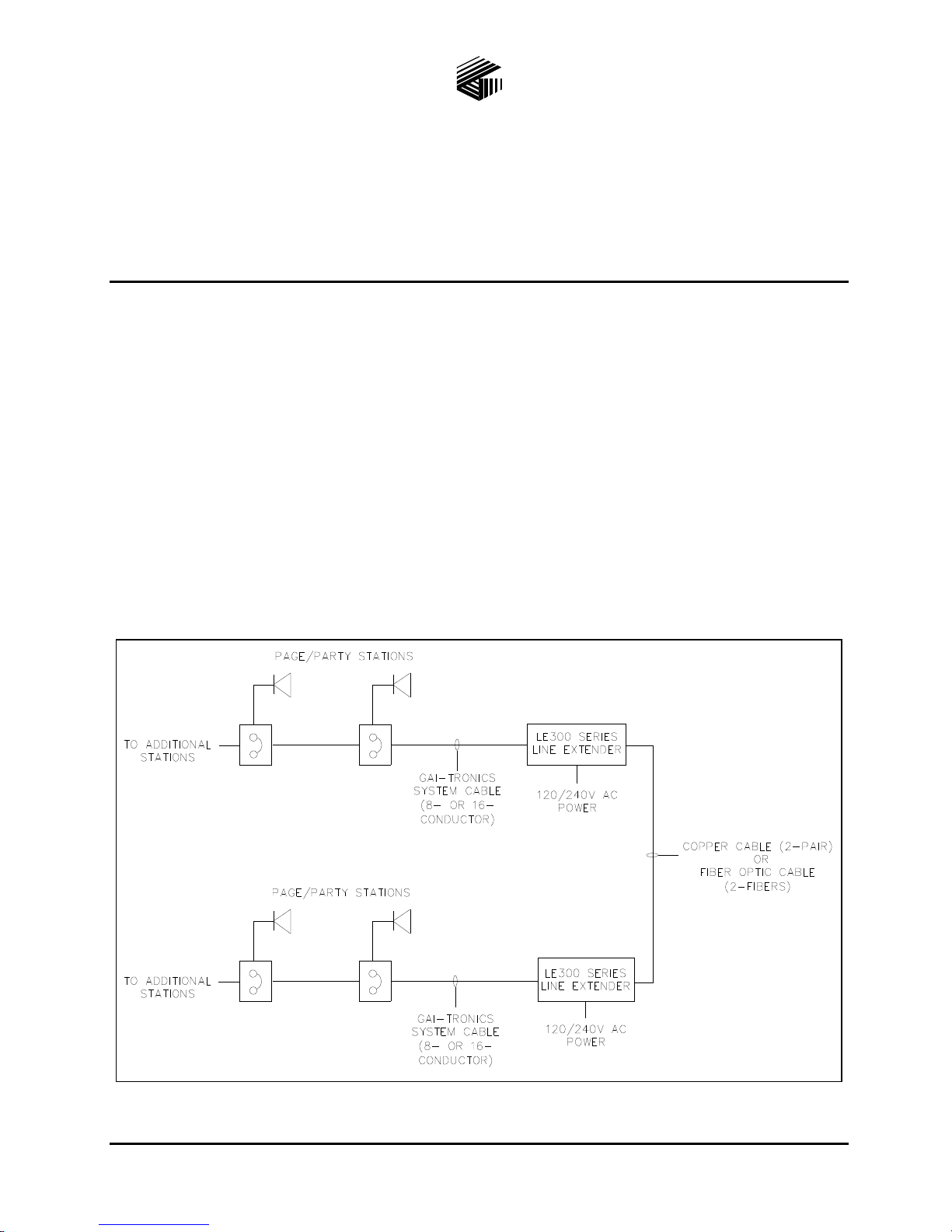
Point-to-Point Page/Party®System Connection..................................................................................................21
Point to Multi-point Page/Party®System Connection ........................................................................................22
Series Connection of Page/Party®System ..........................................................................................................23
Rules for Interconnecting More than Two Model LE300s .................................................................................24
Installation ....................................................................................................................................26
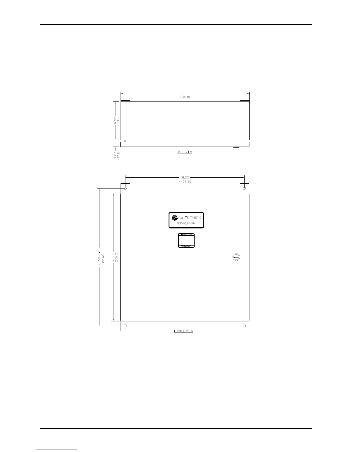
Mounting................................................................................................................................................26
Wiring....................................................................................................................................................27
Power Connections .............................................................................................................................................27
Page/Party®System Cable Connection...............................................................................................................27
T1/E1 Data Connections .....................................................................................................................................28
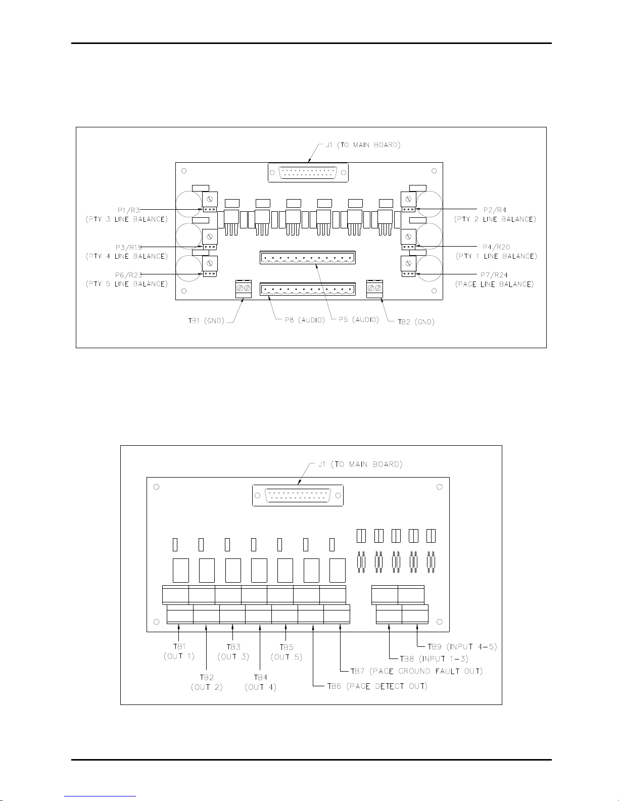
Contact Closure Input Connections ....................................................................................................................29
Contact Closure Output Connections..................................................................................................................30
Page Line Audio Monitoring Connections .........................................................................................................32
Verifying the Proper Line Balance Resistance ...................................................................................................32
Distributing Line Balance Resistance .................................................................................................................33
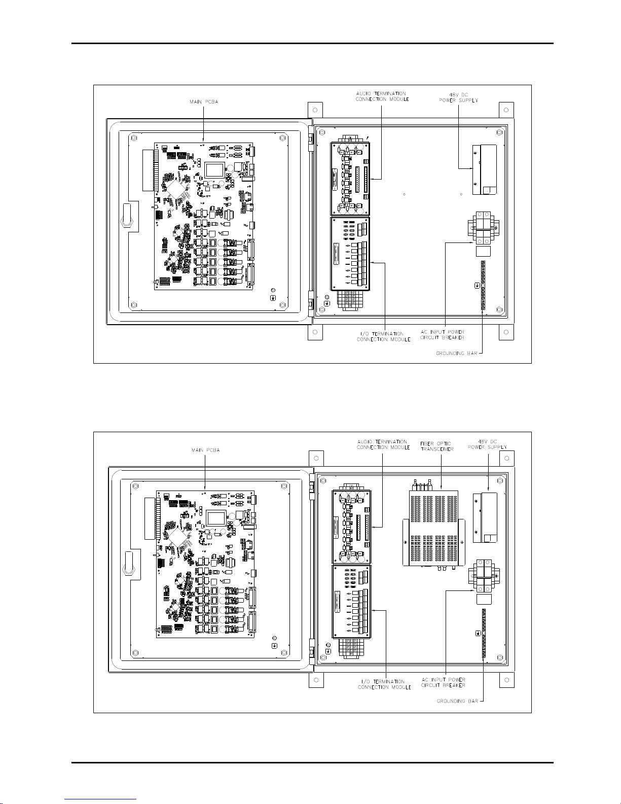
Fiber Optic Cable Connections............................................................................................................34
Fiber Optic Transceiver Set-Up (Models LE300-MM, LE300-SM, LE300-MM1, and LE300-
SM1).......................................................................................................................................................35
Verification of Proper Operation ........................................................................................................................36
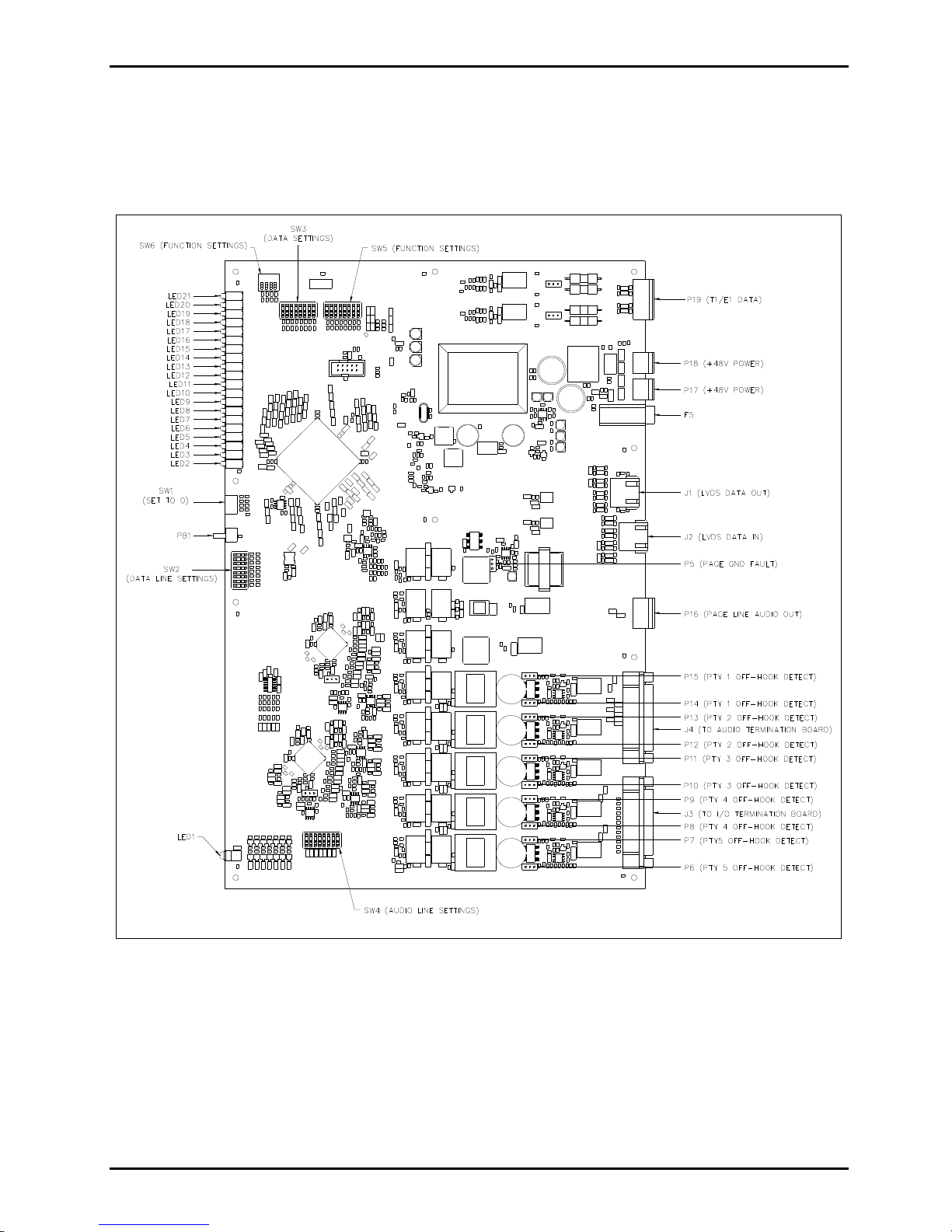
Summary of PC Board Connections and Settings.......................................................................38
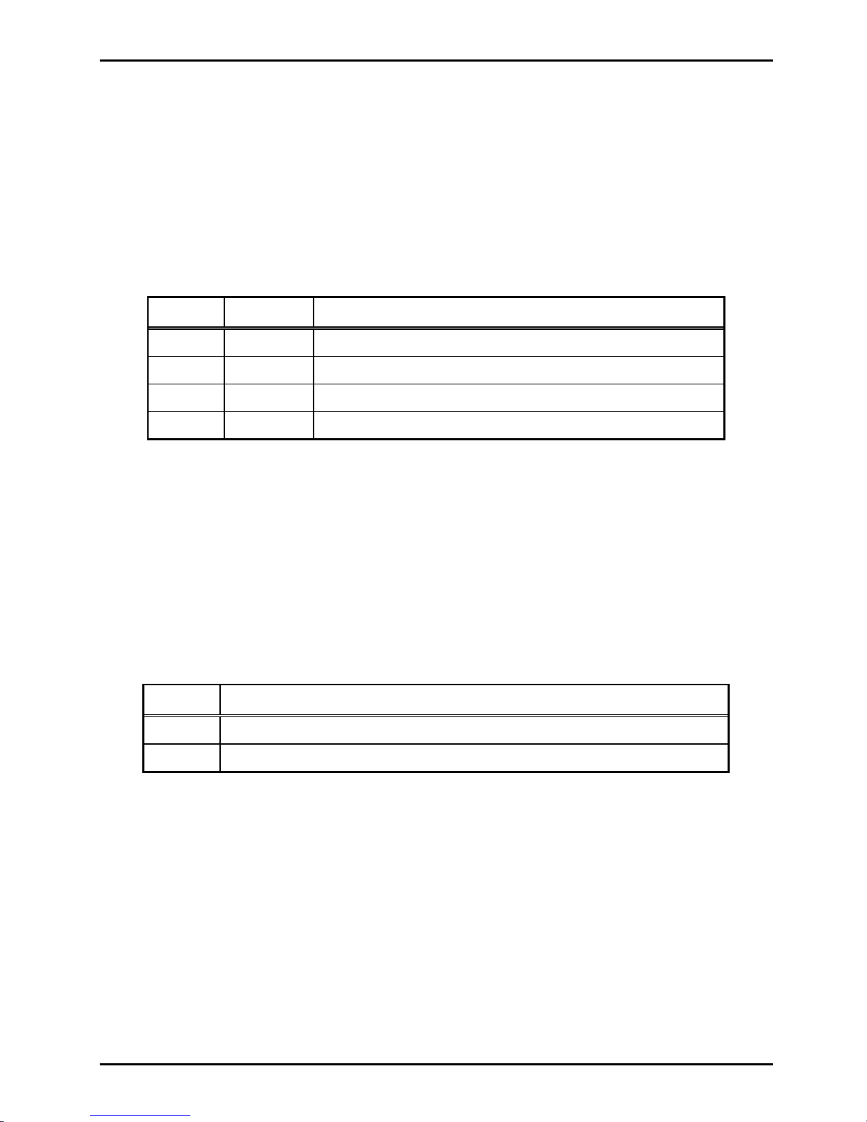
Recording the Settings..................................................................................................................42
Testing and Troubleshooting........................................................................................................45
Generating Audio Test Signals............................................................................................................45
Function Testing....................................................................................................................................46
Specifications ................................................................................................................................47
Replacement Parts................................................................................................................................52
Frequently Asked Questions.........................................................................................................53

PUB.42004-735L2D
GAI-TRONICS 3030 KUTZTOWN RD. READING, PA 19605 USA
610-777-1374 800-492-1212 Fax: 610-796-5954
VISIT WWW.GAI-TRONICS.COM FOR PRODUCT LITERATURE AND MANUALS
GAI-TRONICS®
A HU BBEL LCO MPANY
Model LE300 Series Wall-Mount
Page/Party®Line Extenders
Confidentiality Notice
This manual is provided solely as an operation, installation, and maintenance guide and contains sensitive
business and technical information that is confidential and proprietary to GAI-Tronics. GAI-Tronics
retains all intellectual property and other rights in or to the information contained herein, and such
information may only be used in connection with the operation of your GAI-Tronics product or system.
This manual may not be disclosed in any form, in whole or in part, directly or indirectly, to any third party.
General Information
The Model LE300 Series Line Extenders are used in pairs to extend the operating distance of Page/Party®,
SmartSeries or ICS Page/Party®systems. Two system cable segments are connected through the line
extender using either a 2-pair copper cable or fiber optic cable depending on the distance required. The
local and remote cable segments are electrically isolated through the line extenders. Refer to Figure 1 for a
typical block diagram.
Figure 1. Typical System Block Diagram

Pub. 42004-735L2D
MODEL LE300 SERIES WALL-MOUNT PAGE/PARTY®LINE EXTENDERS Page 2 of 53
p:\standard ioms - current release\42004 instr. manuals\42004-735l2d.doc
02/16
Line Extender and Sub-Component Details
Refer to Figure 2 through Figure 4 below for dimensional information and sub-component layout of the
LE300 Series Line Extenders.
Figure 2. Model LE300 Series Outline

Pub. 42004-735L2D
MODEL LE300 SERIES WALL-MOUNT PAGE/PARTY®LINE EXTENDERS Page 3 of 53
p:\standard ioms - current release\42004 instr. manuals\42004-735l2d.doc
02/16
Model LE300
Figure 3. Interior View of Components - Model LE300
Model LE300-MM, LE300-SM, LE300-MM1, and LE300-SM1
Figure 4. Interior View of Components - Models LE300-XXX

Pub. 42004-735L2D
MODEL LE300 SERIES WALL-MOUNT PAGE/PARTY®LINE EXTENDERS Page 4 of 53
p:\standard ioms - current release\42004 instr. manuals\42004-735l2d.doc
02/16
Audio Termination Connection Module
The page line and party line 1–5 conductors of the Page/Party®system cable connect to the audio
termination audio connection module. This board also can provide the 33-ohm line balance resistance
needed for the audio lines. Audio line functions are described later in this manual.
Figure 5. Audio Termination Connection Module
Input/Output (I/O) Termination Connection Module
The I/O Termination Connection Module is for connecting the control wiring needed to send contact
closures across the line extenders. I/O features and functions are described later in this manual.
Figure 6. Input/Output (I/O) Connection Module

Pub. 42004-735L2D
MODEL LE300 SERIES WALL-MOUNT PAGE/PARTY®LINE EXTENDERS Page 5 of 53
p:\standard ioms - current release\42004 instr. manuals\42004-735l2d.doc
02/16
Main PCBA
The Main PCBA contains all the central processing and line driver circuitry for the line extender. The
board contains numerous connectors, switches and jumpers for setting the line extender operating
parameters. Figure 7 below identifies the various components on the main PCBA. Features and functions
of each component are described later in this manual.
Figure 7. 69443-xxx Main PCBA

Pub. 42004-735L2D
MODEL LE300 SERIES WALL-MOUNT PAGE/PARTY®LINE EXTENDERS Page 6 of 53
p:\standard ioms - current release\42004 instr. manuals\42004-735l2d.doc
02/16
Features and Functions
The Model LE300 Series Page/Party®Line Extenders provide the following features between Page/Party®
system cables.
Page Line Audio Transmission
A pair of Model LE300s provides page line audio transmission between two Page/Party®system cables.
This transmission is half-duplex operation.
When the line extender detects a peak audio level equal or to or above the Peak Voltage Level Detection
Threshold, it immediately switches audio “on” in that direction for the Transmission Direction Hold
Time. Audio from the other direction is muted and ignored during that time. Audio is not switched “off”
until it is continuously below the Peak Voltage Level Detection Threshold for the Transmission Direction
Hold Time. The DIP switch SW2 positions 5-7, located on the main PCBA, selects Peak Voltage Level
Detection Threshold and Transmission Direction Hold Time. Refer to Figure 7 for the location of switch
SW2 on the main PCBA and the tables below for setting this option.
Table 1. Transmission Direction Hold Time Settings on Main PCBA
SW2-5 SW2-6 Transmission Direction Hold Time
Open* Open * 1280 milliseconds
Closed Open 640 milliseconds
Open Closed 160 milliseconds
Closed Closed 40 milliseconds
NOTES:1. Changes to this parameter take effect without cycling power.
2. *Indicates default position.
Table 2. Peak Voltage Level Detection Threshold on Main PCBA
SW2-7 Peak Voltage Level Detection Threshold
Open* −12 dB relative to nominal
Closed −24 dB relative to nominal
NOTES:1. Changes to this parameter take effect without cycling power.
2. *Indicates default position.

Pub. 42004-735L2D
MODEL LE300 SERIES WALL-MOUNT PAGE/PARTY®LINE EXTENDERS Page 7 of 53
p:\standard ioms - current release\42004 instr. manuals\42004-735l2d.doc
02/16
Page Line Audio Monitoring Output
The Model LE300 provides a balanced 600-ohm audio output for monitoring audio on both the local and
remote page lines. The LE300 mixes the local and remote page line audio and routes it to the 600-ohm
audio output terminals. This audio can be sent to any external audio device (recorder, radio transmitter,
amplifier, etc.) with an input impedance equal to or greater than 600 ohms. The audio output gain is
adjustable using DIP switch SW3 positions five through eight on the main PCBA. Refer to Figure 7 for
the location of switch SW3 on the main PCBA and the tables below for setting options.
Table 3. Page Line Monitor Output Gain Setting on Main PCBA
SW3-5 SW3-6 SW3-7 SW3-8
Monitor Output
Gain
Open* Open* Open* Open* 0 dB
Closed Open Open Open −30 dB
Open Closed Open Open −27 dB
Closed Closed Open Open −24 dB
Open Open Closed Open −21 dB
Closed Open Closed Open −18 dB
Open Closed Closed Open −15 dB
Closed Closed Closed Open −12 dB
Open Open Open Closed −9 dB
Closed Open Open Closed −6 dB
Open Closed Open Closed −3 dB
Closed Closed Open Closed 0 dB
Open Open Closed Closed +3 dB
Closed Open Closed Closed +6 dB
Open Closed Closed Closed +9 dB
Closed Closed Closed Closed +12 dB
NOTES:1. Changes to this parameter take effect without cycling power.
2. *Indicates default position.

Pub. 42004-735L2D
MODEL LE300 SERIES WALL-MOUNT PAGE/PARTY®LINE EXTENDERS Page 8 of 53
p:\standard ioms - current release\42004 instr. manuals\42004-735l2d.doc
02/16
Page Line Audio Detect Output Contact
The Model LE300 provides a contact closure output that activates whenever audio is detected on the page
line. The contact can be set to close when audio is detected at the local page line, the remote page line, or
both. Typically this contact is used in conjunction with the page line audio monitoring output to provide a
control contact to external devices or systems when page line audio is present. The contact remains active
for one second after the audio is no longer detected. DIP switch SW5 positions six and seven enables or
disables the output contact. Refer to Figure 7 for the location of switch SW5 on the main PCBA and the
table below for setting this option.
Table 4. Page Line Audio Detect Contact Main PCBA
SW5-6 SW5-7 Audio Detect Contact Operation
Closed Closed Disabled
Open Closed Local page line audio activates the contact
Closed Open Remote page line audio activates the contact
Open* Open* Both Local and Remote page line audio activates the contact
NOTES:1. Changes to this parameter take effect without cycling power.
2. *Indicates default position.
Page Line FSK Data Transmission (SmartSeries Systems)
A pair of Model LE300 Line Extenders re-generates the FSK data transmission between two SmartSeries
Page/Party®system cables. FSK data transmission occurs on the page line allowing SmartSeries
Page/Party stations to communicate with the system control cabinet. For proper operation, both line
extenders must have this feature enabled by setting DIP switch SW5 position one. Refer to Figure 7 for
the location of switch SW5 on the main PCBA and the table below for setting this option.
Table 5. Page Line FSK Transmission on Main PCBA
SW5-1 Page Line FSK Transmission
Open* FSK data is disabled.
Closed FSK data is enabled.
NOTES:1. Changes to this parameter take effect without cycling power.
2. *Indicates default position.
NOTE:FSK operation and VLC operation (described below) cannot be enabled at the same time.
FSK operation is only used with SmartSeries systems.
VLC operation is only used within NON-SmartSeries systems. If both 50 VLC and FSK are enabled
at the same time, neither feature will function correctly.

Pub. 42004-735L2D
MODEL LE300 SERIES WALL-MOUNT PAGE/PARTY®LINE EXTENDERS Page 9 of 53
p:\standard ioms - current release\42004 instr. manuals\42004-735l2d.doc
02/16
Page Line 50 kHz VLC Transmission
A pair of Model LE300 Line Extenders re-generates the 50 kHz VLC control signal between two
Page/Party®system cables. 50 kHz VLC signaling occurs on the page line and is typically used to alter the
speaker volume of Page/Party®stations equipped VLC receivers. VLC signals may also be used for other
on/off control functions on some Page/Party®systems. For proper operation, both line extenders must
have this feature enabled by closing DIP switch SW5 position two. Refer to Figure 7 for the location of
switch SW5 on the main PCBA and the table below for setting options.
Table 6. Page Line 50 kHz VLC Transmission Setting on Main PCBA
SW5-2 Page Line 50 kHz VLC Transmission
Open* 50 kHz VLC is disabled
Closed 50 kHz VLC is enabled
NOTES:1. Changes to this parameter take effect without cycling power.
2. *Indicates default position.
NOTE:FSK operation and VLC operation (described above) cannot be enabled at the same time.
FSK operation is only used with SmartSeries systems.
VLC operation is only used within NON-SmartSeries systems. If both 50 VLC and FSK are enabled
at the same time, neither feature will function correctly.
Page Line Ground Fault Detection
The Model LE300 Line Extenders provide page line ground fault detection on the local Page/Party®
system cable. If multiple LE300s are connected to the same Page/Party®system cable segment, only one
page line ground fault detector may be enabled. A shorting clip setting at header P5 on the main PCBA
enables the page line ground fault detection. Refer to Figure 7 for the location of header P5 on the main
PCBA and the table below for setting options:
Table 7. Page Line Ground Fault Detection Setting on Main PCBA
P5 Shorting Clip Page Line Ground Fault Detection
Pins 1–2* Page line ground fault detection is disabled.
Pins 2–3 Page line ground fault detection is enabled.
Removed Page line ground fault detection is disabled.
NOTES:
1. If connecting an LE300 to the same system cable segment as an ADVANCE Page/Party®Interface
(PPI) card, disable the LE300 page line ground fault detector. The PPI card contains the ground fault
detector. If both ground fault circuits are enabled simultaneously, intermittent SmartSeries FSK data
errors will occur between the PPI card and SmartSeries stations.
2. Changes to this parameter take effect without cycling power.
3. *Indicates default position.

Pub. 42004-735L2D
MODEL LE300 SERIES WALL-MOUNT PAGE/PARTY®LINE EXTENDERS Page 10 of 53
p:\standard ioms - current release\42004 instr. manuals\42004-735l2d.doc
02/16
Page Line Ground Fault Re-generation
When a ground fault is detected at a remote LE300 line extender, the ground fault can be duplicated on the
local Page/Party®system cable. DIP switch SW5 position 3 enables regeneration of the ground fault.
Refer to Figure 7 for the location of switch SW5 on the main PCBA and the table below for setting this
option.
Table 8. Page Line Ground Fault Regeneration Setting on Main PCBA
SW5-3 Page Line Ground Fault Regeneration
Open* Disabled – Page line ground faults detected on the remote system cable are NOT
regenerated on the local system cable.
Closed Enabled – Page line ground faults detected on the remote system cable are regenerated on
the local system cable.
NOTES:
1. The ground fault regeneration feature is used in SmartSeries systems to allow a ground fault on the
remote cable segment to be detected by the system control cabinet. Disable this feature if the line
extender is not installed in this type system.
2. Changes to this parameter take effect without cycling power.
3. *Indicates default position.
Page Line Ground Fault Output Contact
The Model LE300 provides a relay contact that activates whenever a ground fault is detected on the local
page line, remote page line or both the page lines. The ground fault detection feature (described above)
must be enabled. The contact output can be used to activate an external device or system which
annunciates the fault condition. The DIP switch SW5 positions four and five configure which page line
ground faults activate this contact. Refer to Figure 7 for the location of switch SW5 on the main PCBA
and the table below for setting this option.
Table 9. Page Line Ground Fault Contact Setting on Main PCBA
SW5-4 SW5-5 Page Line Ground Fault Contact
Closed Closed Disabled
Closed Open Remote page line ground fault activates the contact.
Open Closed Local page line ground fault activates the contact.
Open* Open* Both Local and Remote page line ground faults activate the contact.
NOTES:1. Changes to this parameter take effect without cycling power.
2. *Indicates default position.

Pub. 42004-735L2D
MODEL LE300 SERIES WALL-MOUNT PAGE/PARTY®LINE EXTENDERS Page 11 of 53
p:\standard ioms - current release\42004 instr. manuals\42004-735l2d.doc
02/16
Party Line Audio Transmission
A pair of Model LE300 Line Extenders provides full duplex party line audio between two Page/Party®
system cables, for party lines one through five. During on-hook conditions of the party lines (meaning no
handset stations are in-use), the LE300 will mute the local party line analog circuits. If it is necessary to
have party line audio enabled even when no stations are off-hook, DIP switch SW6-3 may be closed to
disable this muting feature. This switch affects the on-hook muting function of all five party lines
simultaneously. Refer to Figure 7 for the location of switch SW6 on the main PCBA and the table below
for setting this option.
Table 10. Party Line On-Hook Muting Setting on Main PCBA
SW6-3 Party Line On-Hook Muting
Open* Enabled – local party lines are muted when no handset stations are in-use.
Closed Disabled – party line audio is never muted.
NOTES:1. Changes to this parameter take effect without cycling power.
2. *Indicates default position.
Party Line Off-Hook Detection
The Model LE300 Line Extenders provide off-hook detection on the local Page/Party®system cable for
party lines one through five. An off-hook condition means a handset station is in use. If multiple line
extenders are connected to the same Page/Party®system cable segment, only one off-hook detector can be
enabled. If connecting an LE300 to the same system cable segment as an ADVANCE Page/Party®
Interface (PPI) card, disable the LE300 off-hook detection for party lines one and two. The PPI card
contains off-hook detection for party lines one and two.
Several shorting clips (P6–P15) are used to enable the off-hook detection feature on party line one through
five. Two shorting clips are associated with each party line and must be set to the same position for proper
operation. Party lines one through five are configured independently. Refer to Figure 7 for the location of
P6–P15 on the main PCBA and the table below for setting this option.

Pub. 42004-735L2D
MODEL LE300 SERIES WALL-MOUNT PAGE/PARTY®LINE EXTENDERS Page 12 of 53
p:\standard ioms - current release\42004 instr. manuals\42004-735l2d.doc
02/16
Table 11. Party Line Off-Hook Detection Setting on Main PCBA
Party Line Headers Shorting Clip Off-Hook Detection
Party Line 1 P15, P14
Pins 1–2* Disabled
Pins 2–3 Enabled
Removed Disabled
Party Line 2 P13, P12
Pins 1–2* Disabled
Pins 2–3 Enabled
Removed Disabled
Party Line 3 P11, P10
Pins 1–2* Disabled
Pins 2–3 Enabled
Removed Disabled
Party Line 4 P9, P8
Pins 1–2* Disabled
Pins 2–3 Enabled
Removed Disabled
Party Line 5 P7, P6
Pins 1–2* Disabled
Pins 2–3 Enabled
Removed Disabled
NOTES: 1. Changes to this parameter take effect without cycling power.
2. *Indicates default position.
Party Line Off-Hook Regeneration
When an off-hook handset station is detected, the LE300 can transmit the off-hook condition to remote
line extenders so that it is duplicated on the remote Page/Party®system cable. Typically this feature is
used in systems that contain a telephone interface device so that the caller is transferred to the party line
when a handset station answers the call. DIP switch SW6 position two is used to enable this feature. This
switch affects the off-hook regeneration function of all five party lines. Refer to Figure 7 for the location
SW6 on the main PCBA and the table below for setting this option.
Table 12. Off-Hook Regeneration on Main PCBA
SW6-2 Off-Hook Regeneration Setting
Open* Enabled – an off hook condition on the local party line is regenerated at the
remote line extender.
Closed Disabled
NOTES:1. Changes to this parameter take effect without cycling power.
2. *Indicates default position.

Pub. 42004-735L2D
MODEL LE300 SERIES WALL-MOUNT PAGE/PARTY®LINE EXTENDERS Page 13 of 53
p:\standard ioms - current release\42004 instr. manuals\42004-735l2d.doc
02/16
Audio Line Connection Relays
The Model LE300 has relays that disconnect the page line, party lines one through five and the page
monitoring output connections from the main PCBA. The disconnect feature is used for special
applications such as connection of a single party line system or other scenarios in which a particular audio
line is not physically connected to the line extender. DIP switch SW4 is used to control the audio line
disconnect feature. Refer to Figure 7 for the location of SW4 on the main PCBA and the table below for
setting this option.
Table 13. Audio Line Connection Relay Settings on Main PCBA
Audio Line Switch SW4 Setting Field Wiring
Party Line 5 SW4-1 Open Disconnected
Closed* Connected
Party Line 4 SW4-2 Open Disconnected
Closed* Connected
Party Line 3 SW4-3 Open Disconnected
Closed* Connected
Party Line 2 SW4-4 Open Disconnected
Closed* Connected
Party Line 1 SW4-5 Open Disconnected
Closed* Connected
Page Line SW4-6 Open Disconnected
Closed* Connected
Page Monitor SW4-7 Open Disconnected
Closed* Connected
N/A SW4-8 Open Not used.
Closed*
NOTES:1. Changes to this parameter take effect without cycling power.
2. *Indicates default position.
Audio Line Muting
In some system configurations, the Page/Party®system cable is not connected to the line extender. In this
case, all audio lines (page and party lines 1–5) should be muted since they are not physically connected.
DIP switch SW6 position 4 on the Main PCBA enables this feature. If this feature is enabled, it is
unnecessary to disconnect the audio lines using the audio line relays (mentioned above). Refer to Figure 7
for the location of SW6 on the Main PCBA and the table below for setting options.

Pub. 42004-735L2D
MODEL LE300 SERIES WALL-MOUNT PAGE/PARTY®LINE EXTENDERS Page 14 of 53
p:\standard ioms - current release\42004 instr. manuals\42004-735l2d.doc
02/16
Table 14. Audio Line Mute Setting on Main PCBA
SW6-4 Mute Analog Lines Setting
Open* Disabled - Party lines 1–5 and page line are operational.
Closed Enabled - Party lines 1–5 and page line are muted.
NOTES:1. Changes to this parameter take effect without cycling power.
2. *Indicates default position.
Page/Party® Line Balance
For proper system operation, the page line and party lines 1–5 must be terminated with a resistance of
approximately 33 ohms. The Model LE300 provides potentiometers to set the line balance resistance on
the page line and five party lines. The line balance resistors are located on the Audio Termination
Connection Module next to the page and party line terminal blocks. The line balance resistors are
adjustable or can be disabled using shorting clips P1–P7.
If connecting an LE300 to the same system cable segment as an ADVANCE Page/Party®Interface (PPI)
card, disable the line balance for party lines 1, 2 and the page line. The PPI card provides the line balance
resistors for these audio lines. Refer to Figure 3 or Figure 4 for the location of the Audio Termination
Audio Connection Module. Refer to Figure 5 for the location of the jumpers and potentiometers on the
Audio Termination PBCA and the table below for setting details.

Pub. 42004-735L2D
MODEL LE300 SERIES WALL-MOUNT PAGE/PARTY®LINE EXTENDERS Page 15 of 53
p:\standard ioms - current release\42004 instr. manuals\42004-735l2d.doc
02/16
Table 15. Page/Party® Line Balance Settings on Audio Termination Connection Module
Audio Line Header Shorting Clip Line Balance Adjustment
Potentiometer
Party Line 5 P6
Pins 1–2* Disabled
R23Pins 2–3 Enabled
Removed Disabled
Party Line 4 P3
Pins 1–2* Disabled
R19Pins 2–3 Enabled
Removed Disabled
Party Line 3 P1
Pins 1–2* Disabled
R3Pins 2–3 Enabled
Removed Disabled
Party Line 2 P2
Pins 1–2* Disabled
R4Pins 2–3 Enabled
Removed Disabled
Party Line 1 P4
Pins 1–2* Disabled
R20Pins 2–3 Enabled
Removed Disabled
Page Line P7
Pins 1–2* Disabled
R24Pins 2–3 Enabled
Removed Disabled
NOTES:*Indicates default position.
Contact Closure Inputs & Relay Outputs (I/O)
Five independent contact closures can be transmitted across a pair of Line Extenders meaning that an
active input contact on the local Line Extender results in the corresponding output relay contact energizing
on the remote Line Extender. Contact closures are bi-directional.
Example: Closing a switch contact across input #1 of the local Line Extender results in relay output #1
activating on the remote Line Extender and vice versa. When the input contact is removed the
corresponding output relay de-activates. No switch or jumper setting is required on the Main PCBA for
configuring the I/O feature.
NOTE:Any active output contacts will deactivate if the data link is broken between the Line Extenders.

Pub. 42004-735L2D
MODEL LE300 SERIES WALL-MOUNT PAGE/PARTY®LINE EXTENDERS Page 16 of 53
p:\standard ioms - current release\42004 instr. manuals\42004-735l2d.doc
02/16
Echo Cancellation
Line echo (also known as electric or hybrid echo) is created by the electrical circuitry connected to a two-
wire (full duplex) audio system. Echo is inherent in all full-duplex audio systems and is affected by the
audio line length and line impedance mismatches. The presence of audible echoes results in undesirable
audio quality. This kind of quality degradation is inherent in network equipment and end-user phone
devices.
To minimize echo, the Model LE300 performs an echo cancellation sequence on party lines 1 through 5.
The echo cancellation process takes approximately 15 seconds and is performed automatically one minute
after power is applied to the LE300. This delay allows all power levels to stabilize prior to performing
echo cancellation.
NOTE:Signal impulses are transmitted onto the party lines during the echo cancellation process. Handset
stations that are in use on a party line will hear the signals in the handset receiver. For troubleshooting
purposes, the one-minute delay may be disabled by closing DIP switch SW6 position 1. Refer to Figure 7
for the location of SW6 on the Main PCBA and the table below for setting details.
Table 16. Echo Cancellation Power-On Delay Setting on Main PCBA
SW6-1 Echo Cancellation Power-On Delay
Open* One minute
Closed No delay
NOTES:1. Changes to this parameter take effect when cycling power.
2. *Indicates default position.
Manual Initiation of Echo Canceling
Echo cancellation can be manually initiated as described below.
Press and release push button PB1 on the Main PCBA three times. The push button must be pressed for at
least 0.25 second and no more than 2 seconds each time. The timing requirement is meant to prevent
accidental requests. If an error is made with the push-button timing, the sequence must be repeated from
the beginning.
The LEDs on the Main PCBA will indicate the progress of the echo canceling sequence. One column of
LEDs turns on after each push button press release until the sequence is started. Once the sequence is
started, those LEDs remain on, and a countdown timer is displayed on the remaining LEDs. The LEDs
turn OFF after the echo cancellation training sequence is complete.
Data Links between Line Extenders
The LE300 is equipped with two different data link types for connecting to another line extender. The two
data types are T1/E1 and Low Voltage Differential Signaling (LVDS). The type of data connection(s)
required is determined by the system architecture. It is possible to use both types at the same time to
achieve complex system architectures. Each data type, the intended use, and the applicable switch settings
are described below.

Pub. 42004-735L2D
MODEL LE300 SERIES WALL-MOUNT PAGE/PARTY®LINE EXTENDERS Page 17 of 53
p:\standard ioms - current release\42004 instr. manuals\42004-735l2d.doc
02/16
T1/E1 Data Link
The T1/E1 data link connection is the most common and is used when one pair of Model LE300 line
extenders are connected in point to point system architecture over a long distance. The T1/E1 carrier
technology uses dedicated copper cable or fiber optic cable when equipped with a T1/E1 fiber optic
modem. The distance between line extenders determines the type of connection needed. Copper wire
connections between the line extenders require a 2-pair cable and will operate at up to 6000 feet using No.
22 AWG wire. For distances greater than 6000 feet, a T1/E1 fiber optic transceiver and fiber optic cable
must be used. Model LE300-XXX includes a fiber optic transceiver.
NOTE: The Model LE300 is NOT designed for use with the public switched telephone network.
Model LE300-MM is not compatible with Model LE300-MM1.
Model LE300-SM is not compatible with Model LE300-SM1.
Low Voltage Differential Signaling (LVDS) Data Link
The LVDS data link connection is used to connect two or more LE300 line extenders in a “daisy chain”
fashion when the line extenders are located within 10 meters of each other. The LVDS data link requires a
straight-through category 5e cable between line extenders. Each line extender contains an LVDS data “in”
port and an LVDS data “out” port. The “out” port of the first line extender connects to the “in” port of the
next line extender. This connection scheme can be used to link up to a maximum of eight line extenders
and is typically used when multiple line extenders are installed in a central location.

Pub. 42004-735L2D
MODEL LE300 SERIES WALL-MOUNT PAGE/PARTY®LINE EXTENDERS Page 18 of 53
p:\standard ioms - current release\42004 instr. manuals\42004-735l2d.doc
02/16
Configuring the Data Links
The T1/E1 and LVDS data link parameters between line extenders must be configured using multiple DIP
switch settings on the main PCBA. The following sections describe each parameter and the switch
settings.
T1/E1 Data Format Selection
The LE300 supports both T1 and E1data line connections between units. T1 is a digital circuit that uses
the DS-1 (Digital Signaling level 1) signaling format to transmit voice/data at 1.544 Mbps. T1 can carry
up to 24 digital channels for voice or data. E1 is the European equivalent of the T1, except E1 carries
information at the rate of 2.048 Mbps. E1 is used to transmit 30 digital channels for voice or data plus one
channel for signaling, and one channel for framing and maintenance.
DIP switch SW5 position eight on the main PCBA selects the data link format for the digital audio
transmission between line extenders. Both line extenders must be set to the same format. Refer to Figure
7 for the location of SW5 on the main PCBA and the table below for setting details.
Table 17. Data Format Setting on Main PCBA
SW5-8 Format
Open* T1 Mode (1.544Mbps, 24-channel)
Closed E1 Mode (2.048Mbps, 32-channel)
NOTES:1. Changes to this parameter take effect after cycling power.
2. *Indicates default position.
T1 Line Build-out Settings
This option allows the user to control the wave shape being output by the transmitter. This helps to correct
problems related to long copper cables. Improperly setting this switch will cause signal degradation. The
proper setting refers to the cable distance between two LE300 line extenders. If connecting to a fiber optic
transceiver, it refers to the copper cable distance between the LE300 main PCBA and the fiber optic
transceiver and should be set to 0–133 feet (default setting). DIP switches SW2 positions one through three
on the main PCBA select the line-build out parameters. Refer to Figure 7 for the location of SW2 on the
main PCBA and the table below for setting details.
Table 18. T1 Line Length Setting on Main PCBA
SW2-1 SW2-2 SW2-3 T1 Line Length
Open (up)* Open (up)* Open (up)* 0 to 133 feet
Closed (down) Open (up) Open (up) 133 to 266 feet
Open (up) Closed (down) Open (up) 266 to 399 feet
Closed (down) Closed (down) Open (up) 399 to 533 feet
Open (up) Open (up) Closed (down) 533 to 655 feet
NOTES:1. Changes to this parameter take effect without cycling power.
2. *Indicates default position.
3. These switches have no effect in E1 mode.
This manual suits for next models
4
Table of contents
Other GAI-Tronics Extender manuals