Version: GLATC2CalibrationManualV2.1
1. STEP - PREPARATION
1.1 The unit shall be disconected from mains!
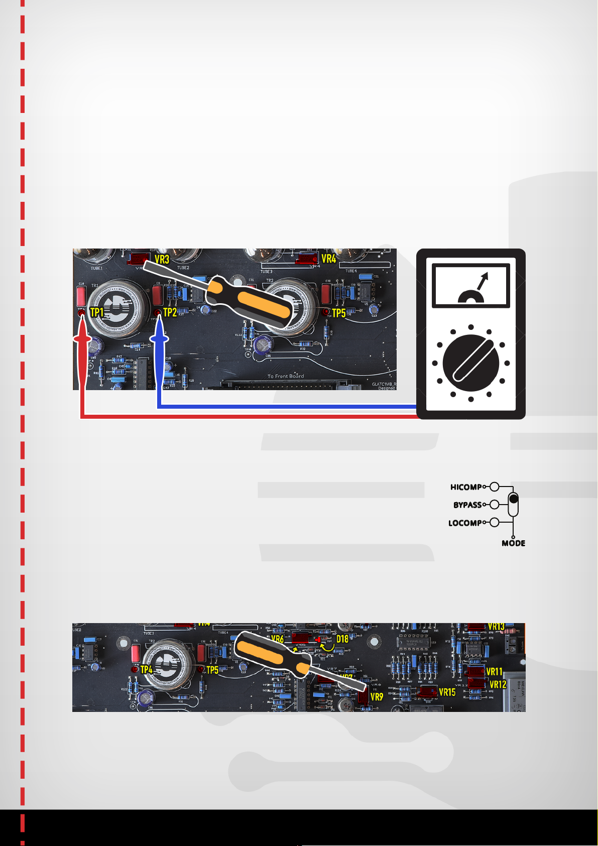
1.2 Check the VU meters on the front panel. Adjust the VU meter with
the front panel screw to make it show the -20dB position as close
as you can.
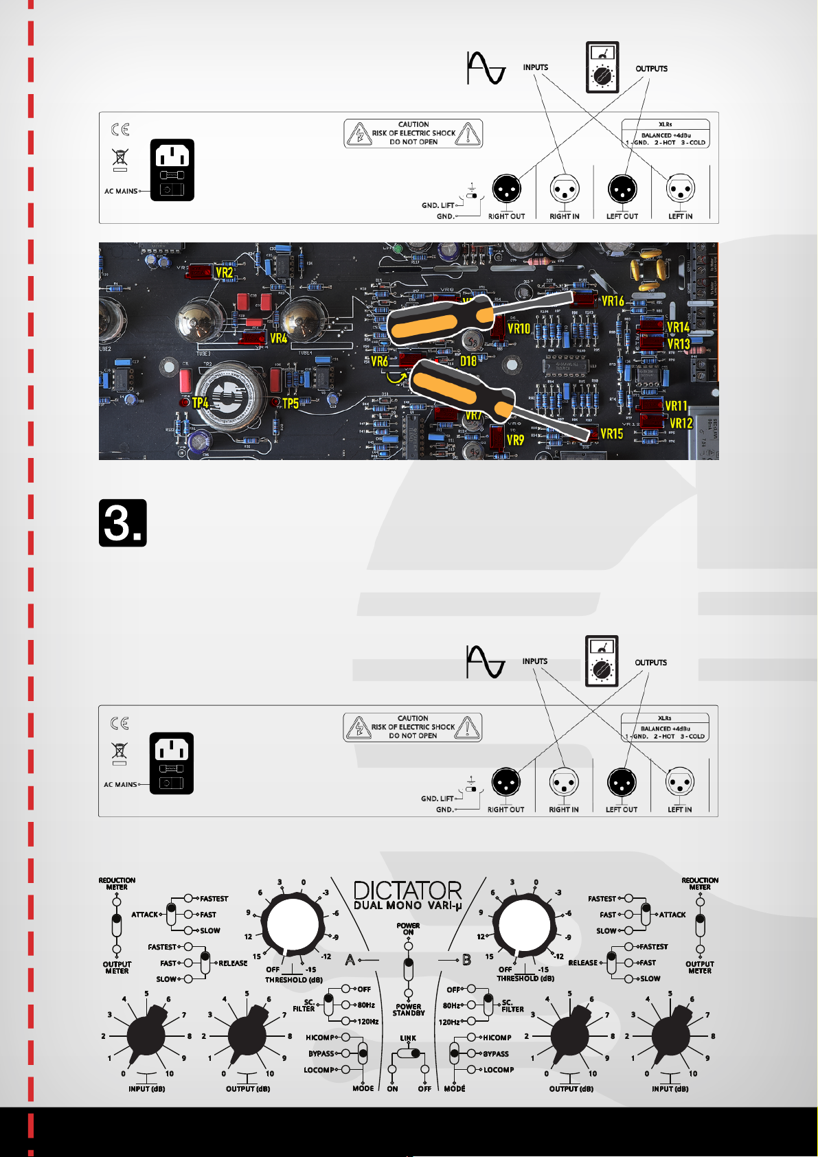
1.3 Now you can connect the unit to mains. Also connect your input
and output signal cables.
1.4 Turn it on and wait 15 minutes to warm up the unit.
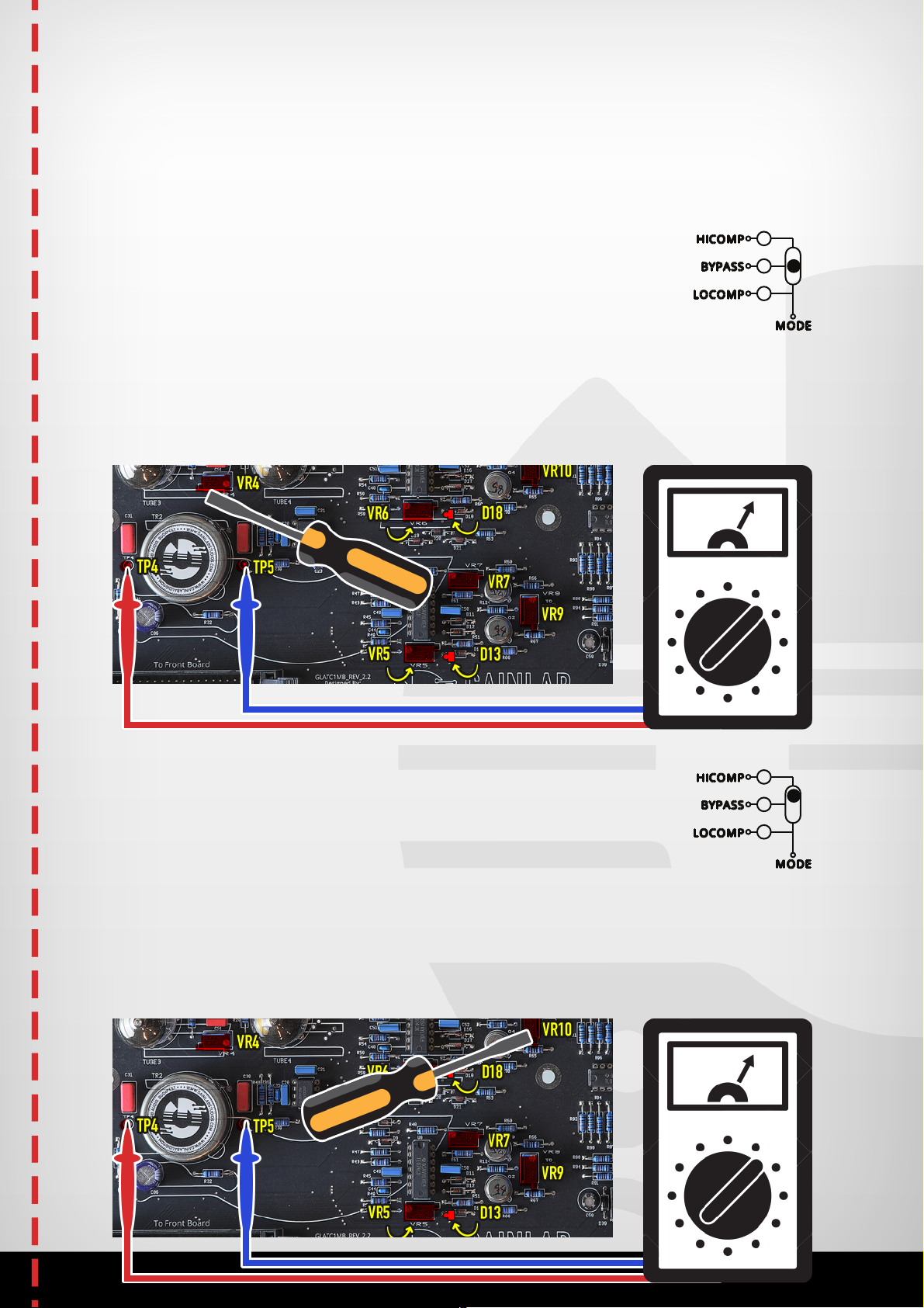
Note: The Attack, Release and Sidechain filter knobs are not used
through the setup process.
The following positions shall remain in the full process:
Attack – Fastest, Relase – Fastest, Sidechain Filter – Off
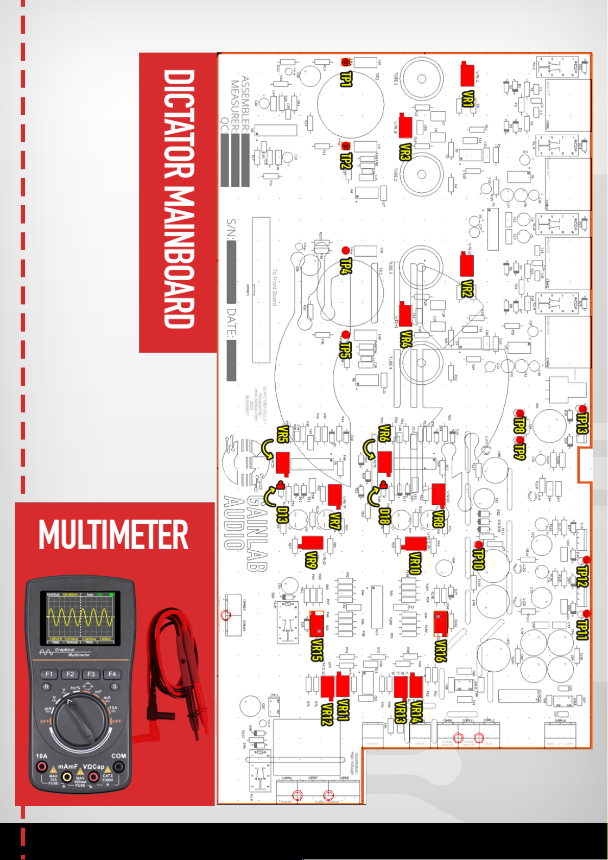
2. STEP - OUTPUT VU METER SETUP
Starting point:
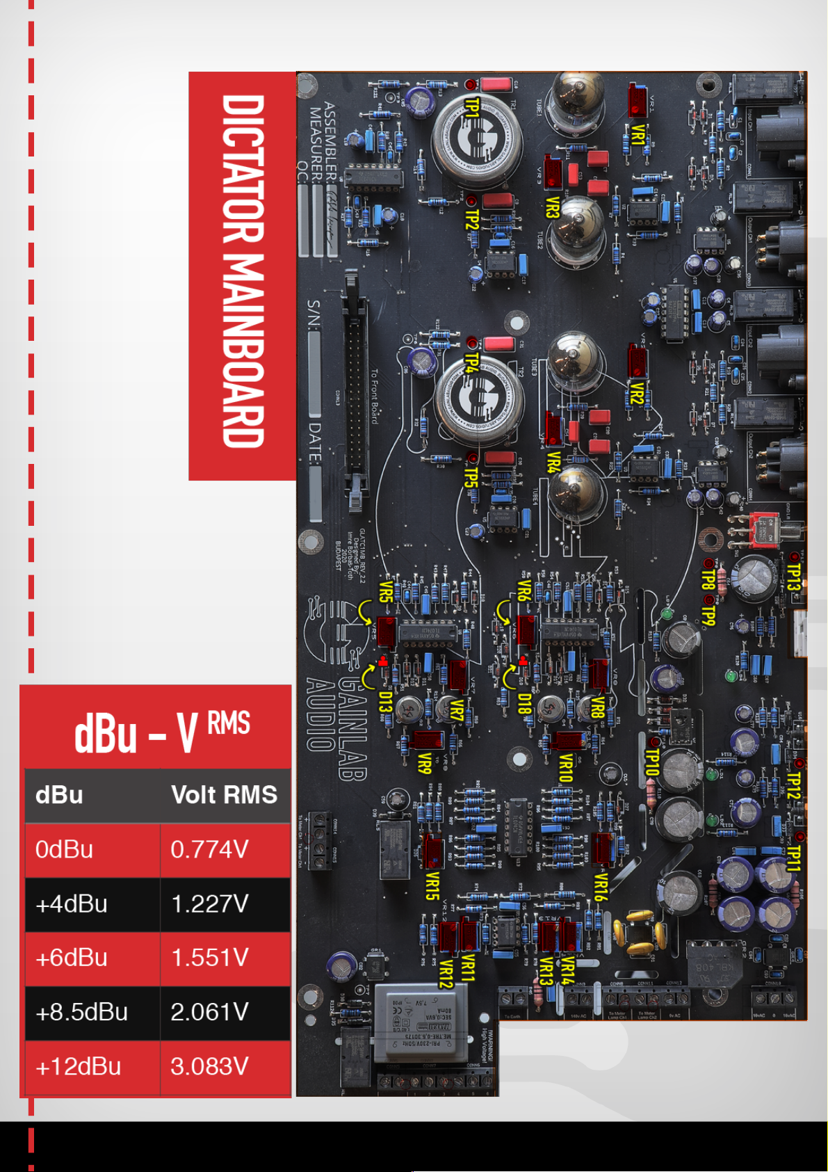
Input signal : +4dBu 1kHz sinewave, on both channels
Switch positions: Mode-Bypass, Meter-Output meter
Measurement process: To measure: the VU meter on front panel
Adjust: VR15 and VR16 trimmer
Target: On both VU meters there shall be 0dB on the output scale