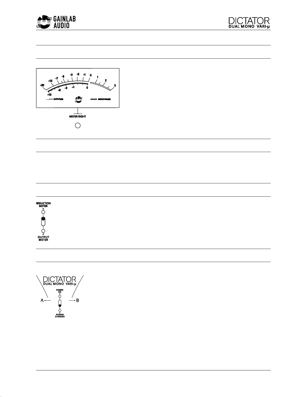
Gainlab Audio DICTATOR DUAL MONO VARI-u User manual


DICTATOR DUAL MONO VARI-μ
OPERATION AND SAFETY PRECAUTIONS
Please note that the GLA-TC2 Dictator Dual Mono is intended for professional use. It’s
not a consumer electronic device. Its installation and use require certain
professional sound engineering knowledge and skills. Lack of this knowledge
may result in malfunction, damage or personal injury.
■Use only grounded electrical outlet!
■Do not open the device and don’t do any modifications on it!
■Do not attempt to repair or replace any of the components unless specifically
instructed to do so in this guide.
■Pay attention to not put any solid matter (flammable things, coin, nail etc) or
liquid (water, alcohol etc.) inside device.
■Do not twist or break the power cord or place heavy objects on it. Doing so
may damage the cable and cause a short circuit. Damaged cables can cause
fire and electric shock!
■Protect the device from intesive external shock! (for example: falling down)
Never use the device in following conditions:
-Extreme temperature
- Moisture
- High humidity
-Rain
- Dust
- Heavy vibration
In the following cases, turn off the machine immediately, unplug the power
cord, and contact us (www.gainlabaudio.com):
■if the mains plug of the appliance is damaged
■if you notice smoke or an unusual odor
1

DICTATOR DUAL MONO VARI-μ
■if any object or liquid gets inside the device,
■if the device has been exposed to rain or other moisture,
■if the device does not operate normally
■Do not connect the appliance to a mains socket to which an electrical
appliance controlled by an inverter, switching power supply (eg refrigerator,
washing machine, microwave, air conditioner) or a appliance with a motor is
connected.
■Depending on the use of the electrical device, power supply noises may
cause a malfunction or audible noise on this unit.If a separate electrical outlet
cannot be used, connect a noise filter between this and the other electrical
appliance.
■The appliance heats up during several hours of continuous operation. This is
normal and not a cause for concern.
■Turn off all devices before connecting the device to other devices. This will
prevent damage to speakers and other equipment.
■Use of the unit near amplifiers or other equipment that contains a transformer
may cause noise. To resolve this issue, relocate the device or move it away
from the interfering device.
■Noise may be caused by using a wireless communication device near the
device, such as a mobile phone. Such noise can occur when making,
receiving, and diverting a call. If you experience this problem, move the
wireless device away from the device or turn it off.
■This unit may interfere with radio and television operation, so do not use near
such receivers.
■If the device is transported to a location with a very different temperature and /
or humidity, moisture may condense inside. Using the device in this condition
may result in damage or malfunction. Therefore, wait a few hours for the
moisture to completely evaporate before using the appliance.
2

DICTATOR DUAL MONO VARI-μ
CLEANING AND MAINTENANCE
Clean the appliance daily with a soft, dry or slightly damp cloth. Use a soft,
abrasion-free cloth to remove stubborn dirt. Then wipe the device with a dry cloth.
Never use benzine, thinner, alcohol or other solvents, strong alkaline or acidic
cleaners as they may cause discoloration and deformation.
OVERVIEW
3
METER A METER B
INPUT GAIN
POWER METER
MODE SWITCH
OUTPUT GAIN
TIME CONTANSTS
HICOMP-LOCOMP
BYPASS SWITCH
SIDECHAIN FILTERMECHANICAL RESET
FOR THE METERS
MECHANICAL RESET
FOR THE METERS
THRESHOLD
LINK-UNLINK SWITCH
IEC SOCKET OUTPUTS
MAIN
POWER SWITCH
FUSE
GROUND LIFT
INPUTS

DICTATOR DUAL MONO VARI-μ
METERS
The meters provide information - optionally - on
the magnitude of the signal level leaving the unit
or the degree of interference from the
compressor.
Being a dual mono compressor, the right-hand
VU meter shows the levels for the B channel,
while the left-hand VU meter shows the levels for
the A channel. Meter units express values in
Volume Units (VU).
MECHANICAL RESET FOR THE METERS
With the device turned off, use a straight slotted screwdriver to turn the mechanical
reset screw until the pointer is in the center of the 20-point value on the lower scale.
METER MODE SWITCH
Specifies whether the instrument clusters show the degree of compression
or the output signal level. Set the mode switch to the up position to
check the amount of compression. Set the mode switch to the down
position to check the output signal level.
DUAL CHANNEL OPERATION
The GLA-TC2 Dictator Dual mono is a dynamics controller
designed for dual channel operation. Thus, the channels
marked A and B can be parameterized completely
independently from each other. All parameters are stepped,
the two channels can be set equally, so they are still
suitable for processing stereo material.!
4

DICTATOR DUAL MONO VARI-μ
INPUT LEVEL SWITCH
With the help of the input signal level controller, it is possible
to increase the signal level entering the device if, for
example, it does not reach the lowest interference threshold
level, or if we want to achieve additional gain on the input
for any reason. To adjust the input signal level, turn the
control knob clockwise until the mark on the control
knob points in the direction of the desired boost level.
OUTPUT LEVEL SWITCH
As a result of the dynamics control, the level of the output
signal of the device suffers a certain level decrease, this is
the case with most dynamics control devices, this is a
normal phenomenon. The output signal level controller
provides an opportunity to compensate for this signal level
loss. To compensate for the output signal level, turn the
output signal level control clockwise until the mark on
the control knob points in the direction of the desired
compensation value.
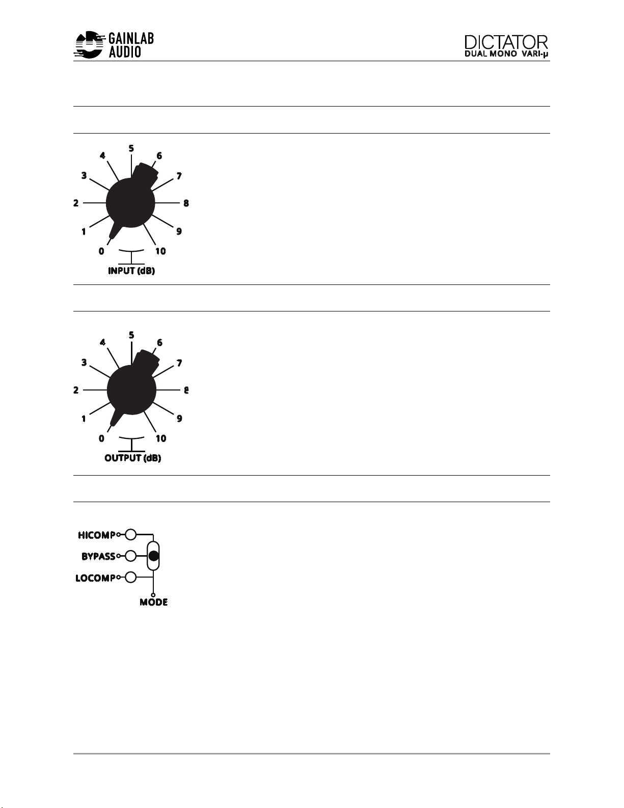
COMPRESSION RATIO, BYPASS
In the case of the DICTATOR Dual Mono, unlike the most
dynamics controllers based on classical electron tube circuits, it
is possible to select two types of compression ratios. In the
LOCOMP position, we get the sound of a classic tubular
compressor such as the Farchild 670 and so on. Generally, this
mode is recommended for use on a combiner and master bus,
and for compressing tracks wich contains fine details. In the
HICOMP position, we can hear a much higher rate of compression, the refraction
curve of which is also much more angular. This mode is especially recommended for
sound design purposes, as well as on buses and tracks where you want to make the
dynamics control audible specifically. At a high threshold value, it is used for buses
intended to be coarser-sounding, and for tracks whose saturation and thickening
may be necessary for mixing. In BYPASS mode, the device galvanically connects its
outputs and inputs, so we can always check the sound of the compression
5

DICTATOR DUAL MONO VARI-μ
compared to the original signal. To select the operating mode, move the switch
until the indicator LED shows the desired operating mode.
TIME CONSTANT - ATTACK
The sound we hear during compression is basically
determined by the speed of the time constants, which in
most cases will result from the nature of the program
signal.
The time constant marked ATTACK can be used to
determine how long it takes for the compressor to reach
the maximum of its intervention range when approaching the set intervention
threshold level. To change the speed at which the procedure rises, move the
switch labeled ATTACK down to set a slower procedure, or move it up to set a
faster procedure. As it is an electron tube circuit, the time constants are
difficult to express in an exact way. The following table helps to determine the
approximate time of the ATTACK parameter:
TIME CONSTANT - RELEASE
The RELEASE parameter determines how long it takes
for the compressor to complete the intervention if the
input signal level falls below the set intervention
threshold level.
To change the run speed of the procedure, move the
switch labeled RELEASE down to set a slower procedure, or move it up to set
a faster procedure.
FASTEST
15ms
FAST
25ms
SLOW
40ms
FASTEST
200ms
FAST
350ms
SLOW
550ms
6

DICTATOR DUAL MONO VARI-μ
INTERVENTION - THRESHOLD
The intervention threshold level, THRESHOLD,
determines the signal level at which the dynamics
controller starts compressing. The timing of the
intervention can be manipulated by the operator by setting
the time constants discussed above, which has a
significant influence on the nature of the sound. The
extent of the interference on the two VU meters can be
monitored
if the instrument cluster mode
toggle switch is set to the up
position. In this case, the home
position of the instrument cluster is
at 0 and shows the degree of signal
level reduction to the left (in the
negative direction) per dBu unit.
After switching between the
LOCOMP and HICOMP positions, it
may be necessary to readjust the threshold level and time constants.
Due to the nature of the equipment, the higher the gain reduction value, the higher
the compression ratio. To adjust the threshold level, turn the knob labeled
THRESHOLD clockwise to set the lower threshold level, or turn the knob
counterclockwise to set the higher threshold level.
CHANNEL LINK/UNLINK
The Dictator Dual Mono is set to A-B channel mode by default. In
such cases, the aim is for the right and left channels to run together
as much as possible. However, in certain situations, it may be
advantageous to eliminate the coexistence of the two channels. In this
case, it is possible to separate the auxiliary circuits of the device. To
separate the auxiliary circuits, move the switch right and check
on the lower indicator lights that the compressor is in the
desired operating condition. Move the switch left to return linked mode.!
7

DICTATOR DUAL MONO VARI-μ
SIDECHAIN FILTER
Depending on the program signal, it is often necessary
for the dynamics controller not to react to deep
frequency components. In such cases, it is advisable to
filter out these low-frequency components from the
auxiliary circuit signal controlling the compressor with a
high-pass filter that does not allow a signal to the control
circuit below a set cut-off frequency. To set the filter, move the switch labeled SC.
FILTER so that the switch’s LED indicator points towards the cut-off frequency
value below which you no longer want to allow a signal to go to the auxiliary
circuit
POWER SWITCH
The unit is switched on with the switch marked POWER. Set the switch
labeled POWER to the up position if you want to turn on the unit. Set
the switch labeled POWER to the down position when not in use.
Due to the tube design of the device, it is advisable to leave a “warm-up
time” of 15-20 minutes before starting use.
ATTENTION! the switch labeled POWER puts the device in standby
mode, does not completely disconnect it from the mains, if you
want to disconnect the device completely from the mains, unplug
the device from the mains or switch off the main switch at the IEC
socket !
GROUND LIFT
The switch on the back of the device allows the outgoing audio
connection to be disconnected from ground, thus eliminating
ground loop phenomena that occur under certain conditions. To
adjust the ground defrost, set the GROUND LIFT switch on the
rear panel to the up position."
8

DICTATOR DUAL MONO VARI-μ
TECHNICAL SPECIFICATIONS
Inputs: 2x Balanced XLR
Outputs: 2x Balanced XLR
Maximum input level: +22dBu
Input impedance: >10Kohm
Maximum output level: >26dBu
Output impedance: <65ohm
THD+N (0dBu): <0.3%
Frequency response: 20Hz-20Khz +/- 1dB
Dimensions: 483mmx280mmx89mm
Weight: 5.3 Kg
Mains voltage: 230V AC (EU version)
110V AC (US version)
9

DICTATOR DUAL MONO VARI-μ
DICTATOR DUAL MONO RECALL SHEET:
10

This manual suits for next models
1
Table of contents
Other Gainlab Audio Recording Equipment manuals