Gainsborough Windsor Series User manual

1
Windsor series manual version 1.0 S.D 25.4.2014

2
Windsor series manual version 1.0 S.D 25.4.2014
1. Cover
2. Contents
3. Pre-installation 1.
4. Pre-installation 2.
5. Pre-installation / water pressure.
6. Installation 1.
7. Installation 2.
8. User Guide 1.
9. User Guide 2.
10. User Guide 3.
11. Maintenance / Trouble shooting.
12. Warranty.

3
Windsor series manual version 1.0 S.D 25.4.2014
Minimum Dimensions for Access: Doorway: -
25mm. Corridor: - 25mm
Consideration must be allowed to manoeuvre the
bath around hallways etc.
This document details the requirements which must
be in place to ensure the bath can be installed cor-
rectly
Floating Floors
The definition covers a multitude of floor finishes. Typical examples below.
It is imperative that before any work is carried out that an understanding of the floor composition is carried out.
1. Floating floor fixed to wood 2. Floating floor fixed to wood 3 Floating Floor on cushion material
Supports over concrete Joists
Dependent upon the sub-structure a decision can be made as to whether it is feasible to install a powered bath
with chair. If the bath is a platform bath this is not an issue as there is little or no lateral load. The issue arises
when it is necessary to support the cantilever effect of the chair and patient.
Read below to address the floating floor that affects your installation:
1.
It is feasible to tackle this type of floor in two ways.
a) Remove a section of the surface floor and ‘build up’ from the concrete sub-floor. This can be done by creating
a ‘tray’ and fill this using a concrete mix. Alternatively timber joists can be anchor bolted to the concrete sub-floor
to provide the needed support. The finish should come level with the surface floor.
b) If the void is small it is acceptable to drive through with Rawl/Coach bolts. This may require a small section of
the surface floor being removed and material such as sheet wood inserted to fill the area.
2.
This type of void requires the surface floor removing and Noggins introduced to brace between the Joists.
Particular attention should be made on the area where the foot plate of the bath is to be sited.
3.
Dependent upon the void size it is usually acceptable to remove the material
(often 100mm/4” polystyrene) and back filling with concrete.
Under No Circumstances should fixing be made to the surface floor alone.
DIMENSIONS
A1390mm B210mm C 640mm
D 750mm E 485mm F1305mm
G1700mm or 1500mm

4
Windsor series manual version 1.0 S.D 25.4.2014
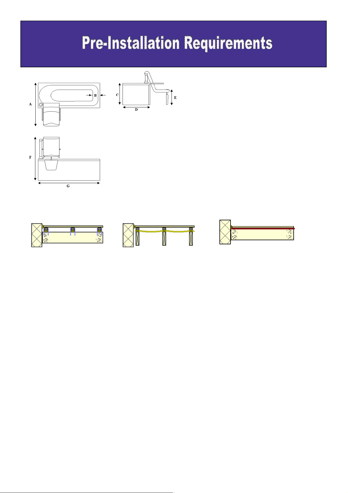
¾” BSP Male hot water inlet, 30mm from the floor, against the wall,
200mm from the left hand side of the front (tap end) of the
bath.
¾” BSP Male cold water inlet, 30mm from the floor, against the
wall, 250mm from the left hand side of the front of the bath.
40mm Waste outlet @ 3ltr/Sec, 30mm from the floor, against the
wall, 290mm from the left hand side of the front of the bath.
A 5 Amp IP65 Non Switch Fused Spur, with 2m of 1.5mm 3 core
round cable protected inside plastic conduit to the bath within
200mm of the tap end of the bath, positioning and specification
to be in accordance with current IEE regulations.
An additional power supply will be required if a spa is fitted.
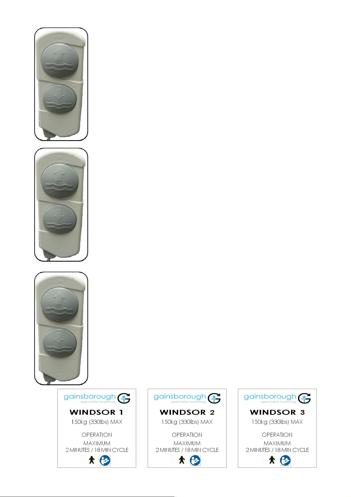
Picture for visual reference only
DIMENSIONS TO BE TAKEN FROM THIS SIDE Minimum distance between the walls and baths bath
sides is 150mm.
When deciding on the position of the bath there are a
number of points that should be considered.
1. Hoist and wheel chair access
2. Access for installation and service
3. Opening doors
4. Distance from walls and other objects
5. Manoeuvring the transfer trolley
6. Under floor heating, pipe work and cables.
The floor directly under the bath and transfer
area must be a solid and even surface.
Particular attention should be paid to the shaded
area on the plan which need to be drilled to a
depth of 100mm for fixing points and must be of
solid construction with no buried services.
Electrical connection & Earth bonding.
A 30mA RCCD is required in compliance with the current IEE regulation. This should be located just outside
the bathroom or on the consumer unit covering that area of the building.
10mm Earth bonding and a minimum of 4mm cross bonding is to be fitted and tested for continuity in
accordance with IEE regulations.

6
Windsor series manual version 1.0 S.D 25.4.2014
Responsibility of the installer.
It is the responsibility of the installer to inspect the product prior to installation to ensure the unit is free of defect or
damage. In the event of a problem the unit must not be installed.
This product complies with internationally recognised safety standards. However you are responsible for any local
codes that may apply.
This product is designed to be installed by a licensed tradesperson. Licensed plumbers and electricians should be
employed to ensure a proper installation. Installers assume all liability for the correct installation procedures.
Only accessories authorized by the manufacturer should be used with this product.
Risk of electric shock. Connect only to a separate circuit protected by a 30mA RCCD.
The unit must be connected to a RCCD. This should be tested on a routine basis. To test the RCCD push the test
button, the RCCD should interrupt power. Push the reset button, power should be restored.
If the RCCD fails to operate in this manner there is a ground current flowing indicating the possibility of electric
shock. Do not use this unit. The unit should be corrected by a qualified representative before any further installation
is undertaken.
Risk of electric shock. Spa motors where fitted should be connected to a separate 30mA RCCD protected outlet.
Note: The unit must not be fitted in the bathroom area unless protected by an RCCD.
Classification & technical data.
Fixed class 1 installation
Type B applied part
Not suitable for use in the presence of flammable anaesthetic mixture with air or oxygen or nitrous oxide.
Rated supply 230v, 240W 60Hz refer to label.
Maximum patient weight: 22 stones . 140kg (transfer system) 150 Kg fixed
Maximum weight of bath and chair . 174kg (empty)
Maximum weight of complete transfer system . 33kg
Suitable for intermittent use only - 2 minutes on - 18 minutes off.
The power pack is low voltage and runs at 24v DC . Immediately after installation and prior to use it is vital that the
bath is connected to a mains supply for at least 24 hours before initial use to ensure the batteries are fully charged.
Failure to comply with this requirement could result in the user not being able in the event of a mains power failure.

7
Windsor series manual version 1.0 S.D 25.4.2014
Do not use sharp knives or instruments to open this product.
Remove the plastic film from all panels.
A. Check with the site owner to confirm the exact installation position.
B. Inspect the unit and panels thoroughly.
C. Ensure all components are present inside the bath pack. (this should include : repair pot, Manual, Waste
kit, SWL sticker, lap belt, floor fixing kit and shower unit assembly. Where applicable) report any missing
items immediately quoting the number on the side of the unit.
D. Remove any existing equipment and materials as necessary to prepare the site.
E. Connect the bath unit on a temporary power supply . This will be indicated by a green light on the status
display (win2/3 only).
F. Raise the seat using the 2 button handset .
G. Fit the shower unit before positioning the bath in the installation position.
H. Manoeuvre the bath into its installation position.
I. Remove the transportation board
J. Mark the position of the floor fixing holes
K. Mark the wall bracket position.
L. Move the bath to allow drilling of the fixing holes
M. Drill 4 x 10mm x 100mm deep in the floor (base plate) Clean out all dust and debris. Drill fixing holes for the
front bath feet.
N. Re-position the bath and fix to the floor using the kit provided, ensure the plates and chrome tube are
level.
O. Fix the wall fixing bracket.
P. Connect the hot and cold water pipes.
Q. Connect the waste pipe.
R. Make the electrical connection .
S. You may need to trim the panels on this product.
T. Fix wooden batons for panel fixing where required.
U. Check for any leaks and set the TMV temperatures. Taps 43°C and the Shower at 38°C
V. Attach the safe working load sticker to the panel and fully test the unit.

Windsor series manual version 1.0 S.D 25.4.2014
1. Prior to entry a carer should ensure that the pick up arm is in the fully lowered position outside of the bath.
This can be achieved by pressing and holding down the “out of water” button on the handset. The arm will
stop automatically when it is fully lowered.
2. The trolley and seated
user can now be
positioned outside the
bath.
5. Raise the arm
using the handset.
6. Raise the seat. Remove the trolley before the
seat traverses.
3. position the seat on to the pick up arm ensuring
that all of the location points are in line
4. Apply wheel
brakes
7. Traverse the seat over
the bath. (support the
bathers legs)
8. Lower the seat into the bath.
Exit is a reversal of the previous. Depressing the “out of water” button to lift the seated user up out of the bath.
Assistance may be required to lift the user’s legs out of the bath. Then traverse out side the bath.
Do not pull or push on the seat or pick up arm as this can result in serious injury.
Position the trolley beneath the seat and continue to lower the seat until the seat locates fully onto the trolley.
When not in use, the pick up arm & seat should be left in the lowered position outside the bath if possible.

9
Windsor series manual version 1.0 S.D 25.4.2014
SERIES 2
To operate the seat in the Upwards direction, press and hold down the “out of
water” button on the handset. The seat will cycle up and out of the bath, when it
reaches the top of it’s stroke the seat will automatically traverse out of the bath.
When at 90°outside the bath the seat will automatically begin lowering. When the
seat reaches the lowest point it will stop. You do not need to remove your finger
from the button.
To send the seat back into the bath hold down the “into water” button and keep it
held down. It will send the seat back into the bath and to the lowest point.
SERIES 1
To operate the seat in the Upwards direction, press and hold down the “out of
water” button on the handset. The seat will cycle up and out of the bath, when it
reaches the top of it’s stroke you must gently traverse out of the bath to 90°.
When at 90°outside the bath the seat can begin lowering. Press and hold the
“out of water” button. When the seat reaches the lowest point it will stop.
To send the seat back into the bath hold down the “into water” button and keep it
held down. The seat will reach it’s highest point. Traverse the seat into the bath
until positioned centrally inside the bath. Press the “into water” button to continue
lowering the seat. When at it’s lowest point the seat will stop.
SERIES 3
To operate the seat in the Upwards direction, press and hold down the “out of
water” button on the handset. The seat will cycle up and out of the bath, when it
reaches the top of it’s stroke the seat will automatically traverse out of the bath.
When at 50°outside the bath the seat will automatically begin lowering the leg lift
pad. The seat will then traverse to 90°. The seat will then begin lowering. When
the seat reaches the lowest point it will stop. You do not need to remove your
finger from the button.
To send the seat back into the bath hold down the “into water” button and keep it
held down. It will send the seat back into the bath and to the lowest point.

10
Windsor series manual version 1.0 S.D 25.4.2014
Intended use Fixed seat system.
Supplied without the transfer trolley the seat is permanently fitted to the bath. All operation remains the same.
A safety lap belt is supplied for added security whilst the user is seated on the chair and during bathing.
It is the responsibility of the user/carer to ensure the lap belt is fitted while the product is in use.
Check the water temperature before use.
To operate the shower open the valve closest to the shower (red
ring) and depress the handset.
This is a hair wash/rinse system only. This is pre set to 38°C.
After use turn off the valve, depress the handset briefly to empty
any water still inside the hose and then place the handset back
into it’s mount.
User safety notes
To reduce the risk of injury do not permit children or persons with infirmities to use this product unless they are
closely supervised at all times.
To avoid injury, exercise care when entering or exciting the bath.
Never drop or insert any objects into any openings.
Do not permit electrical appliances (such as hair dryer, lamp, telephone, radio or television ) within 152cm (60”)
of this product.
Avoid the abuse of alcohol, drugs or medication whilst using the bath.
Warning! Please ensure that hands and objects are kept away from the underside of the seat when lowering
onto the trolley & into the bath.
Ensure all items for bathing including towels, face cloths, soap , shampoo etc. are within easy reach when using
the bath.
To operate the taps open the valve (red) This is pre set to
42°C. If you wish to add cold water to the bath, open the
valve with (blue) to achieve the desired water
temperature.
Please note that the taps supplied with your product may differ from those shown.

11
Windsor series manual version 1.0 S.D 25.4.2014
To get the most out of your Windsor bath we recommend that the unit is cleaned and maintained on a daily
basis.
The chrome seat tube should be cleaned using a silicone based cleaning product (such as Mr Sheen)
Spray a small amount on the tube when the seat is fully raised and wipe with a dry soft cloth. This will avoid any
build up or soap, water or atmospherics.
The bath can be cleaned with a medical disinfectant, especially if the product is to be used with multiple users.
Do not use abrasive type cleaners. Oven cleaners, scouring powders or bleach on this product.
1. Seat will not go down — Check status display, ensure mains power is supplied to the bath (indicated by a green light).
2. Seat will not traverse — Disconnect the power, wait five minutes and re-apply power.
3. Flashing blue light — Disconnect the mains power , wait five minutes and re-apply power.
Code 1: Lift actuator fault : One long flash followed by 1 short flash
---------- ----- ---------- -----
Code 2: Traverse actuator fault : One long flash followed by 2 short flashes
---------- ----- ----- ---------- ----- ----
Code 3: Leg Lift actuator fault : One long flash followed by 3 short flashes
---------- ----- ----- ---------- ----- ----
If any of the above fault codes are indicated on the status display please contact our service department.

12
Windsor series manual version 1.0 S.D 25.4.2014
This product is warranted as being free from defects during the period of warranty. This does not cover minor
blemishes, etc. which may be part of normal manufacturing processes.
The warranty covers manufacturing defects in the products, starting from the date of manufacture. Contact your
Supplier to find out more about the warranty period. The warranty is limited to the value of the purchase price
paid.
The warranty is only valid if the product has been used correctly. Where there are any mechanical or electrical
parts, any damage, misuse or tampering with them will render the warranty invalid. Any sealed electrical boxes
must remain unopened or this will invalidate any warranty.
THERE IS NO OTHER WARRANTY EXPRESSED OR IMPLIED INCLUDING, BUT NOT LIMITED TO, THOSE
OF MERCHANTABILITY AND FITNESS FOR A PARTICULAR PURPOSE. THE FOREGOING WARRANTY IS
LIMITED TO THE TIME PERIOD SPECIFIED FROM THE TIME OF RECEIPT. IN NO EVENT SHALL THE
SUPPLIER BE LIABLE FOR ANY SPECIAL, INCIDENTAL, PUNITIVE, OR CONSEQUENTIAL DAMAGES I
NCLUDING BUT NOT LIMITED TO; LOSS OF USE. WHILE THIS WARRANTY GIVES YOU SPECIFIC LEGAL
RIGHTS YOU MAY ALSO HAVE OTHER RIGHTS WHICH MAY VARY FROM STATE TO STATE.
Other Gainsborough Bathtub manuals
Popular Bathtub manuals by other brands

Claybrook
Claybrook Orbit Bath 1300 installation manual

Arjo
Arjo Malibu 1600 Assembly and installation instructions

Crosswater
Crosswater Puro US-N15CS installation instructions

Kohler
Kohler K-1113 Installation and care guide

American Standard
American Standard Cadet Whirlpool 2771.018 parts list

Kohler
Kohler K-1123-RA Roughing-In Guide