Gainsborough Gplus HOME PORT User manual

G+ HOME PORT
User Guide


WELCOME TO
THE EASIER WAY
TO ACCESS
YOUR HOME

This guide will show you how to install your
G+ Home Port.
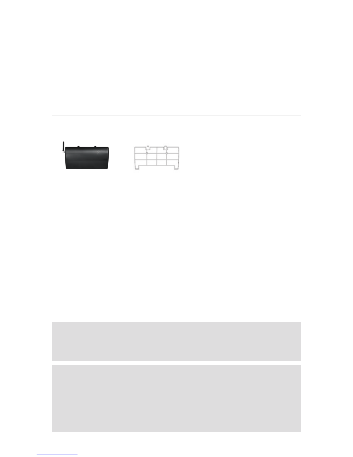
G+ HOME PORT MOUNTING BRACKET
WHAT’S IN YOUR G+ HOME PORT BOX?
This appliance is not intended for use by persons (including children)
with reduced physical, sensory or mental capabilities, or lack of experience
and knowledge, unless they have been given supervision or instruction
concerning use of the appliance by a person responsible for their safety.
Children should be supervised to ensure that they do not play with
the appliance.
Take care! Electricity kills. Switches, power outlets and other fixed wire
products must be installed by a licensed electrical contractor or similarly
qualified person.

CONTENTS
SECTION 1
Overview.................................................................................................................2
Applications 2
Non G+ Control Systems 3
Layout .....................................................................................................................4
Communication overview...................................................................................5
SECTION 2
Installation .............................................................................................................8
Location 8
Mounting instructions 8
Wiring Instructions Guidelines .......................................................................10
Input (from controlling devices) 10
Power 11
Setup......................................................................................................................12
Programming 12
SECTION 3
General Specifications.......................................................................................16


1
OVERVIEW, LAYOUT,
COMMUNICATION
OVERVIEW

2Section 1 Overview
Overview
The G+ Home Port is an electrically powered device used within the
G+ Access System to enable non G+ Systems to control G+ Devices.
The G+ Home Port is wired to a non G+ control system.
The G+ Home Port controls G+ Devices via a RF, (Radio Frequency), link.
APPLICATIONS
G+ Devices a G+ Home Port can control include:
• G+ Locksets
AND
• G+ Smart Boxes
AND
• G+ enabled Gliderol garage doors.
There is no limit to the number of G+ Devices that can be simultaneously
operated by a G+ Home Port.

3Section 1 Overview
NON G+ CONTROL SYSTEMS
Examples of suitable*systems that could activate a G+ Home
Port include:
• Home automation systems
• Building access system
*A suitable system is one that activates the G+ Home Port by:
• Voltage Free Contact / Dry contact for > 100ms
• Voltage Input
– Deactivated: 0V
– Activated: 5 -24 VDC , 12 -24 VAC for > 100ms
NOTE: The installer is responsible for ensuring the compatibility of systems
being connected to the G+ Home Port.

4Section 1 Layout
Connections when controlling an Electric G+ Lockset
Layout
Teach –
Lockset
Teach –
Smart Box 3
Remove device
Teach light
Programming
Teach –
Smart Box 1
Teach –
Smart Box 2
Input 1 –
Smart Box 1
Power
Input 2 –
Smart Box 2/
Lockset Privacy
Input 3 –
Smart Box 3/
Lockset

5Section 1 Communication Overview
Communication Overview
G+ Locksets
Receives
commands from
the G+ Home Port
Up to 3 x groups of
G+ Smart Boxes /
G+ Enabled Gliderol
Garage Door
Receives commands
from the G+ Home
Port
Non G+ Controlled System
Command Inputs
to G+ Home Port


2
INSTALLATION,
WIRING AND SETUP

8Section 2 Installation
Installation
LOCATION
The G+ Home Port is to be installed in a secure, dry environment out
of direct sunlight.
MOUNTING INSTRUCTIONS
The installer should consider strain relief for all cables.
Step 1: Fix Mounting Plate to wall with screws (not supplied), as shown.
Step 2: Clip Housing into Mounting Plate
NOTE: The installation location, (walls / materials), can affect the operation
distance between the G+ Home Port and a G+ Lockset / G+ Smart Box.
This should be checked by the installer prior to installation. Do not install
the G+ Home Port in a metal box as this will severely interfere with the
RF transmission range.
1 2

9Section 2 Installation
Step 3: Connect wiring
See Section 2 – Wiring Instructions Guidelines (page 10-11)
Step 4: Snap on Protective Cover
3
4

10
INPUT (from controlling devices)
Function overview
The G+ Home Port has 3 inputs that control the following
In the case of a G+ Lockset
– Input 1: N/A
– Input 2: Privacy Mode
– Input 3: Passage Mode
In the case of a G+ Smart Box or G+ enabled Gliderol garage door
– Input 1: a G+ Smart Box / G+ enabled Gliderol garage door
– Input 2: a G+ Smart Box / G+ enabled Gliderol garage door
– Input 3: a G+ Smart Box / G+ enabled Gliderol garage door
Additional devices a can be assigned to the 3 inputs.
The inputs will only respond once per activation i.e. the G+ Home Port
will only send a command once to the Powered G+ Lockset or G+ Smart
Box for every time the Input is activated. Leaving the Input activated
will not result in the G+ Home Port continuing to send the command.
Wiring Instructions Guidelines
TAKE CARE - ELECTRICITY KILLS!
Switches, power outlets and other fixed wired products must be installed
by a licensed electrical contractor or similarly qualified person.
NOTE: The installer should consider strain relief for all cables.
NOTE: The installer is responsible for ensuring the compatibility of systems
being connected to the G+ Home Port.
Section 2 Wiring

11Section 2 Wiring
Typical wiring for Voltage Free / Dry contacts
Typical wiring for Voltage Input
Input 1
Input 3
Input 2
Input 1
Input 3
Input 2
POWER
This appliance shall only be supplied at safety extra low voltage
corresponding to the marking on the appliance.
Connection of 12/24 V AC/DC
NOTE: This appliance is only to be used with the power supply unit provided
with the appliance.

12 Section 2 Setup
Setup
PROGRAMMING
Programming G+ Home Port to a G+ Lockset
• Press the G+ Home Port Lock Teach button until the teach light is on.
• Press the G+ Lockset Teach button, (via paper clip or similar), until
the Teach Confirmation Sound is heard – approx 3 seconds.
• Wait for Lockset to emit a single beep confirming successful
recognition of the G+ Home Port.
• Wait for G+ Lockset to end its Teach session.
• The G+ Home Port will automatically end its teach session after
approximately 5 minutes.
– The G+ Home Port teach session can be ended earlier by activating
one of its inputs.
Programming G+ Home Port to a G+ Smart Box
• Press the appropriate G+ Home Port Lock Teach button until light is on.
• Press the appropriate G+ Smart Box Teach button until the Teach
Light illuminates and blinks – approx 3 seconds.
• Wait for G+ Smart Box Light to blink confirming successful
recognition of the G+ Home Port.
• Wait for G+ Smart Box to end its Teach session.
• The G+ Home Port will automatically end its teach session after
approximately 5 minutes.
– The G+ Home Port teach session can be ended earlier by activating
one of its inputs.

13Section 2 Setup
Removing G+ Devices from a G+ Home Port
• Press the Remove Button on the G+ Home Port until the light
is illuminated.
• Place the G+ Device into teach mode and wait until the
Teach Confirmation is heard / seen.
• Wait for G+ Device to end its Teach session.
• The G+ Home Port will automatically end its teach session after
approximately 5 minutes.
– The G+ Home Port teach session can be ended earlier by activating
one of its inputs.

Table of contents
Popular Computer Accessories manuals by other brands

Thermaltake
Thermaltake Bach Vx vf4000 series user manual

perixx
perixx PERIDUO-212 user manual

ekwb
ekwb EK-Supremacy MX Series installation manual

RaidSonic
RaidSonic IB-RD3219StU3-B Specifications

Spectrum Industries
Spectrum Industries 37342 Assembly instructions

Kensington
Kensington K64440 Instruction guide