Gakken Japanino User manual

1Otona no Kagaku
2
How to Assemble and Use the Supplement
8-bit Micro Computer "Japanino" & the P.O.V.
(Persistence of Vision)
How to assemble the supplement
Assembly time for the P.O.V:
Approximately 30 minutes
Things you will need
A screwdriver, three new AAA alkaline batteries, or
three zinc-carbon batteries
(* Oxyride batteries have high voltage. Using these
batteries may break the circuit, so please refrain from
using them.)
* Please use a USB extension cable if necessary. A USB 2.0-compliant
cable that is 1 m or less in length works well.
* Please purchase one from a shop, if you need one.
●Materials used in this kit
Micro Computer board (red): Epoxy, Connector on the Micro Computer board (white or black), connector on the battery box (white), and connector, etc. on the LED unit (black): PA66, LED unit board: Phenol
P.O.V. casing (white), handle gear (white), handle knob (white), speed-increasing gear (white), connecting rod (white), LED holders (white), back cover (white), cable holder (white), stand A (white), and stand B (white): POM
Screws, washer head screws (black): Iron (with chromate plating)
Battery contacts: Copper (with nickel plating). Terminals on the board: Copper (with tin plating)
* Please dispose of this product in accordance with local regulations.
Notes for tightening screws
When tightening screws, rmly press the screwdriver straight
against the screw and turn. It is said that 70 percent of the
force applied is used for pushing against the screw and
30 percent for turning it. The types of screws used for the
supplement are those that carve grooves into the plastic as
they are inserted (self-threading). For this reason, the screw
hole may be damaged if you exert too much force when
tightening the screw. Use a small screwdriver with a grip
diameter of about 2 cm.
Full-scale image of a
screwdriver
CAUTION
Please be sure to read the following instructions before assembling this kit.
●
This kit includes screws and other small parts. Be careful not to swallow them. There is a risk of suocation.
●
There are parts with pointed edges on the Micro Computer board (Japanino) and the LED unit (the edges of the
circuit boards, the edges of connectors, cut sections of parts on the backside of the circuit boards, circuit board
pins, etc.). There is a risk of unexpected injury, so be careful when handling parts with pointed edges. Place this kit
out of the reach of small children when not in use.
●
Staring at flashing LEDs for long periods of time may cause you to exhibit symptoms of feeling sick such as
nausea, etc. (The extent of this may vary from person to person.) Take caution when using the P.O.V. for long
periods of time. Take extra precautions when showing the P.O.V. to small children, in particular, by not allowing
them to view it for long periods of time, etc.
●
The Japanino is constructed using parts that have been deemed safe to use; however, please take care when
using the Japanino, by ensuring that small children do not lick the printed circuit boards or wiring cords (The
Japanino and P.O.V. meet the safety standards for heavy metals and PVC.)
●
Do not connect the Japanino to a 100 VAC power supply as it would be extremely dangerous to do so.
●
Do not touch the Japanino with wet hands. Doing so may cause the Japanino to malfunction due to rusting, etc.
●
Do not let the Japanino get wet as it is not waterproof. Should the Japanino happen to get wet, wipe away any
moisture with a moisture-absorbent cloth.
●
Do not store the Japanino in locations that are high-temperature, have high humidity, or have a lot of dust.
●
Remove the Japanino from the USB terminal on the PC when there are lightning strikes, etc. happening. There is
a risk of electric shock.
●
The Japanino is a precision device. Do not place it in locations where temperatures are too high or too low, such
as in direct sunlight, near heating or air conditioning equipment, etc.
●
The Japanino is constructed using precision electronic parts. To prevent breakdown from static electricity, make
sure to touch something metal to remove static electricity from your body before touching the main unit. In
particular, if you touch the main unit during battery-powered operation without discharging static electricity
from your body, there is a risk of the Japanino breaking.
●
Be sure to use the versions designated by GAKKEN for the OS software used in your computer. The Japanino may
not operate properly if you use versions other than those designated.
●
When using the battery box, please make sure to remove the Japanino from the USB terminal on your computer
before using.
●
Do not use the battery box for any device other than the Japanino. Using it for another device carries a risk of
heat being generated, etc. due to improper use such as short-circuiting.
●
Do not connect the battery box directly to the P.O.V. without going through the Japanino. Doing so may cause
the P.O.V. to break.
●
If metal objects (coins, paper clips, staples, wires, metal belts of watches, etc.) make contact with the front or
back of the Japanino, there is a risk of heat generating due to malfunction or short-circuiting. Take care not to let
metal touch the surface of the circuit board.
●
The Japanino uses a resettable fuse. For safety reasons, please use under conditions where the amount of current
flowing from the USB terminal or batteries is 0.4 A or less (the Japanino is rated for 0.5 A, but it is not
recommended that you use it at an amount close to the limit). If you use the Japanino at a value that exceeds this,
the internal resistance will increase, generating heat. Unlike with an ordinary fuse, the resettable fuse can be used
again if the temperature returns to normal and the Japanino reverts to initial conditions; however, heat will again
be generated until the cause of the problem is eliminated. Because not knowing the cause of the malfunction
could lead to accidents, please stop/discontinue use in such cases (you might burn yourself if you touch the
resettable fuse while it is generating heat).
●
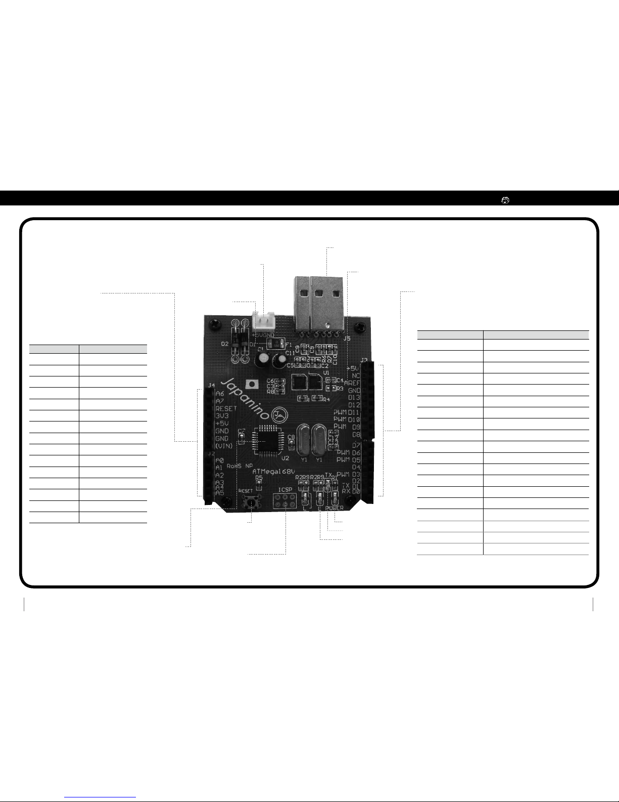
The part on the Japanino labeled "+5V" provides about 4.6 V of voltage during USB connection and about 4 V of
voltage with a reduction of about 0.4 V from the battery voltage during connection to the battery box. Use under
such conditions that the current from this part does not exceed 0.4 A.
●
The part on the Japanino labeled with "3V3" has not been stabilized. If using USB connection, check the voltage
before using when connecting the battery box.
●
The ICSP terminal on the Japanino is a part that is to be purchased by the customer separately and soldered on
by hand. Please be advised that if attaching an ICSP terminal, you are doing so at your own risk. GAKKEN will not
oer any support with regard to this matter. When soldering on the part, please be careful that you do not burn
yourself or start any res.
●
Please do not short together the places on the Japanino marked GND, 5V, and 3V3 with a pin, etc.
●
Please make sure to have a parent or other adult supervise any children age 15 and under who are going to use
the Japanino. GAKKEN will not take any responsibility for accidents, incidents, etc. that may occur should a child
use the kit unsupervised.
●
Do not modify the Japanino. GAKKEN will not perform repairs, etc. to modications.
●
Putting together your own circuits for the Japanino to try out, or putting together your own circuit for controlling
a dynamic power source not listed in this booklet (such as a 100 VAC power supply, an engine, other batteries,
etc.), is done at your own risk. There is a risk of heat being generated, fire breaking out, the circuit board being
broken, etc. if circuits that you built yourself short out, etc.
●
Do not attempt to put together circuits for controlling devices that can end a human life including ones that
generate fire or make equipment that can cause serious injury for use with the Japanino. GAKKEN will not take
any responsibility for accidents, incidents, etc. occurring with devices that are capable of causing serious injury to
human beings.
●
Please be advised that GAKKEN and copyright holders of software, etc. in this kit will not take any responsibility
for problems occurring either directly or indirectly as a result of the use of this kit.
* Please read the instructions and cautions thoroughly before use.
* For your safety, be sure to follow the instructions in this manual. In addition, do not use any parts that have
become damaged or deformed during use.
●Note 1: For instructions on how to operate your own computer, please refer to the operator's manual for that computer.
●Note: In the explanations, screen shots for Windows 7 and Mac OS X are used; however, the expressions used in those screen shots may dier from what is actually shown on the screen
depending on the OS version or settings, etc. for the screen browser used. Please check your computer's OS and the operator's manual for that OS.
Supported computer models
OS: Windows XP (SP2 or later)/Vista/Windows 7; Mac OS X10.4 or later
Interface: USB 2.0
* Microsoft and Windows are registered trademarks of Microsoft Corporation in the United States and in other countries.
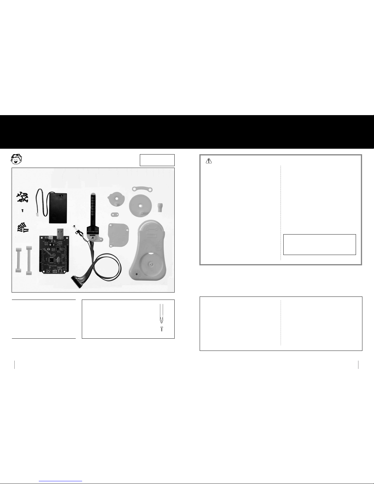
Parts in the Kit
Japanino
(Micro Computer board)
Handle gear
Speed-increasing
gear
Stand A
Stand B
Cable holder
Connecting rod
Back cover
Handle
knob
LED unit (with connector
cable)
Washer head
screws (10)
Small screw (1)
Screws (8)
P.O.V. casing (with speaker)
Battery box (with
connector cable)
* Left over screws are spares.
* The red bag that the board came in
is an antistatic plastic bag. Please use this bag
when putting the board away.
* Company and product names in this booklet
●Company names and product names written in this booklet are
generally registered trademarks of the development manufacturer.
Please note that we do not use the symbols, TM, ©, or ®, in this booklet.
* About GAKKEN's "Japanino"
Micro Computer board
●GAKKEN'S Micro Computer board, "Japanino," is made to be plug-
compatible with the Arduino, but it does not have the exact same
hardware conguration. GAKKEN is not able to guarantee 100% that
sketches that work with the Arduino will also work normally with the
Japanino. GAKKEN can also oer no guarantee that sketches that work
on the Japanino will also work on the Arduino 100% of the time.
●The specications for and ways to use the Japanino may change later
on without prior notice.
●Please be aware that neither GAKKEN nor the copyright holders
or manufacturers of software, etc. used in this kit will not take any
responsibility for any damages, etc. occurring as a result of the use of
technical information provided in this booklet.
* About the IDE
●The IDE introduced in this booklet was completely produced by the
Arduino team.
* The Arduino team: Massimo Banzi, David Cuartielles, Gianluca Martino,
Tom Igoe, and David Mellis
* Other
●Copyrights for the driver software belong to CP Corporation in the
United States.
Three AAA batteries are used in this kit. Incorrect use of the batteries may cause the generation of heat, explosions
or liquid leakage. The following precautions should be taken.
●
Do not use oxyride batteries. Using such batteries may cause the Japanino to break.
●
Ensure that the positive and negative terminals of the batteries are aligned correctly.
●
If liquid that leaked from the batteries gets into your eyes, rinse them well with plenty of water and consult a
doctor immediately. If liquid leaks onto your skin or clothes, wash it o immediately.
●
Always remove the batteries after use.
●
Do not mix old and new batteries.

3Otona no Kagaku
4
Checking operations before assembly
Operating the Japanino and LED unit with batteries
How to assemble the supplement
2
I
nsert the connectors from the battery box, the LED unit, and the
speaker in the main unit casing into the relevant connector plugs on the
Japanino as shown in the diagram, and then turn the switch for the battery
box on. If the LEDs are ashing, then everything should be working.
3 Touch the lead switch. If a beep sound is emitted, everything should
be working.
* Be sure to check
the orientation of
the batteries.
If something isn't working properly…Check the following!
●
Are the batteries new, and have they been inserted in the right direction?
●
Did you plug in each connector in the right place and push each all the way in?
●
Is the switch for the battery box turned to ON?
●
Is the power supply LED on the Japanino main unit (see page 6) lit up?
Note: If you are unable to check that these operations are working
correctly, you will not be able to check the operations on page 6.
Please make sure to check.
How to hold the connector.
Insert the connector into pins D6 to GND.
Insert the connector into
pins A0 and GND.
* If the beep sound continues even af ter you've
taken your hand away, adjust the amount of space
between the terminals on the lead switch so that
there is about 0.5 mm of space between them.
Battery box
Battery box
LED unit
Casing
Japanino
Lead switch
Assembling the P.O.V.
1Affix the speed-increasing gear to the main unit casing with a washer
head screw (being careful not to tighten them too tightly).
2
After passing the tip of the LED unit through the top of the main unit casing, ax
the LED unit to the main unit casing with a washer head screw (being careful not to
tighten them too tightly).
3Screw the lead switch down with the screw (small). Next, screw in the
connecting rod with washer head screws.
4Pull the cable up as shown in the diagram, and then screw in the back
cover using washer head screws.
* Pull the cable up toward the top
to screw in the screw.
* The back cover is attached to protect
the main unit. You do not need to
attach the back cover if you wish to see
the mechanisms inside the main unit. It
will still operate without the back cover
attached.
Speed-increasing gear
Washer head screw
Casing
LED unit
Washer head screw
Casing
Washer head screws
Connecting
rod
Small screw
Lead switch
Washer head screw
Washer head screw
When Attaching Stands to the
Japanino…
5Loosen the cable holder that is wrapped around the speaker cable. After
passing the LED unit and speaker cables through as shown in the diagram,
ax the cable holder using a washer head screw. Tighten down the loosened
cable holder once again.
6Attach the handle gear and handle knob from the front side with washer
head screws to complete.
One cable holder comes already
attached to the main unit casing as
shown in the picture below. This
cable holder is to be loosened.
Attach stand A and stand B by screwing in screws in four places as shown in
the diagram.
* Turn the handle clockwise
to lightly check if the LED unit
swings left and right.
Note: You need not attach the stands if doing so prevents you from being able to insert the Japanino
into the USB slot on your computer. However, in such cases, please take extra precautions to ensure
that the back side of the Japanino does not come into contact with metal during use (if that should
occur, electricity may ow unexpectedly, causing the board to break). Leftover screws can be used
for other DIYs.
Screws Screws
Stand B
Stand A
Japanino (backside)
Handle knob
Washer head screw
Handle gear
Washer head screw
Cable
holder
Washer head screw
LED unit cable
Speaker
cable
1Insert the connectors for the
completed P.O.V. and the battery
box into the connector plugs on
the Japanino (see page 3 for where
to insert). Turn ON the switch on
the battery box. If the LEDs are
ashing, then everything should
be working.
2Turn the handle on the P.O.V. to
make the LED unit swing slowly
left and right. If a beep, beep, beep
sound is emitted on the left side,
then everything should be
working.
Connecting the Completed P.O.V.
to the Japanino to Check
Operations
How the P.O.V. works
If something isn't working properly…Check the following!
●
Did you plug in each of the pins on the connector rmly into the right place?
●
The speaker will emit sound if the lead switch makes contact with the speed-
increasing gear when the projection on the gear is on the left side. Slowly turn
the gear to check it.
Note: If you are unable to check that these operations are working
correctly, you will not be able to try out the experiments on page 9.
Please make sure to conrm that these operations are working.
Beep
Beep
P.O.V .
Battery box
Japanino
Turn it ON.
Beep
When the speed-increasing gear makes
one revolution, it will make a complete
trip around.
LED unit
Speed-
increasing
gear
Perspective diagram
as seen from the front
When the handle is turned
approximately 90°, the
speed-increasing gear
makes one revolution.
Handle
When the speed-
increasing gear makes one
revolution, the switch is
turned on once.
Connecting rod
1Insert three new AAA batteries
into the battery box.
Tur n it
ON.
Pass the tip
of the LED unit all
the way through.
* Either of the wires, grey or black, can
be inserted into the GND pin.
* If the LED unit is left on the left side,
the speaker continues to emit the beep
sound.
Once you've checked everything, turn the
battery box OFF, and unplug the connectors
from the Japanino.
Cable
holder

5Otona no Kagaku
6
Components in the Japanino and Their Functions
There are quite a few characters and symbols imprinted on the Japanino, but there are
not so many of which you actually need to know the meanings.
Most of the parts you should be familiar with are pins*.
The types of pins are roughly divided into three groups, digital input/output pins,
analog input pins, and power supply pins.
Normally, pins are wired in accordance with the sketch (program).
A6
Analog input pin no. 6.
DescriptionSymbol
Analog input pin no. 7.
Adds a RESET button
3.3 V power supply pin. Not usually
used.
Power supply pin. Supplies a 5 V
power supply.
Ground. Negative (-) on power
supply.
Ground. Negative (-) on power
supply.
Not used.
Analog input pin no. 0.Can also be used
as digital pin no. 14.
Analog input pin no. 1.Can also be
used as digital pin no. 15.
Analog input pin no. 2.Can also be
used as digital pin no. 16.
Analog input pin no. 3.Can also be
used as digital pin no. 17.
Analog input pin no. 4.Can also be
used as digital pin no. 18.
Analog input pin no. 5.Can also be
used as digital pin no. 19.
A7
RESET
3V3
+5V
GND
GND
(VIN)
A0
A1
A2
A3
A4
A5
There are a total of 8 analog input pins, including A6 and A7 in
addition to A0 to A5 (the A is short for Analog). The input voltage is
read out from 0 to the power supply voltage (5 V, normally) in 1024
steps. You can connect sensors, volume dials, etc. to these pins. In
addition, you can also use these analog input pins as digital input/
output pins by changing the settings in a sketch (program).
There are a total of 14 pins from D0 to D13 (the D stands for Digital). The input pins and output pins for
digital values of HIGH and LOW can be set freely. The 6 pins of D3, D5, D6, D9, D10, and D11 that are
marked with PWM (for Pulse Width Modulation) can be used as pulse width control output pins. Pins
D0 and D1 can be connected to a PC via USB.
5 V; microcomputer/ATmega168V; USB-serial conversion IC/CP2104; oscillating
frequency, 8 MHz
Analog input pins Digital input/output pins
Specications
Connector for
the battery box
USB connector
Explanations of terms
Power supply ON indicator LED
Reset button
IC chip
ICSP terminal
Pin D13 activity indicator LED
IC chip
Overcurrent protection
(Resettable) Fuse
Place for connecting the
battery box. The battery
box becomes a 5 V (to
be exact, a 4.5 V) power
supply.
Button for resetting the
exchange, etc. of data.
Sometimes used for writing, etc.
of sketches for Mac.
A terminal used for writing,
etc. to a boot loader. Not
normally used.
An Atmel microcontroller
ATmega168V is used. A power-
saving type of IC chip.
Connector for connecting to
a PC with USB
* Pin: For the Japanino, terminals are referred to in this way. Some terminals may also be called "ports" on other circuit boards. Some terminals may be in the form of sockets. The expression "I/O pin" is also
sometimes used when to represent input/output. "I" stands for "Input" and "O" for "Output."
* GND: This stands for "GROUND," the surface of the earth. Electrically speaking, ground refers to earth ground. The ground terminal is connected to the negative (-) on the power supply.
* PWM: This is the abbreviation for "Pulse Width Modulation." By controlling the ratio between ON and OFF times for a given pulse, you can realize analog output with digital pins.
CP2104 from CP Corporation
. Performs USB to serial
conversion.
+5V
Power supply pin. Supplies a 5 V power supply.
DescriptionSymbol
Not connected to anything.
Reference signal pin.
Ground*. Negative (-) on power supply.
Digital input/output pin no. 13 (can be used to monitor the
L LEDs on the circuit board).
Digital input/output pin no. 12.
Digital input/output pin no. 11 (can also be used to output
PWM*).
Digital input/output pin no. 10 (can also be used to output
PWM).
Digital input/output pin no. 8.
Digital input/output pin no. 7.
Digital input/output pin no. 6 (can also be used to output
PWM).
Digital input/output pin no. 5 (can also be used to output
PWM).
Digital input/output pin no. 4.
NC
AREF
GND
D13
D12
PWM D11
PWM D10
PWM D9
D8
D7
PWM D6
PWM D5
D4
Digital input/output pin no. 9 (can also be used to output
PWM).
Digital input/output pin no. 3 (can also be used to output
PWM).
Digital input/output pin no. 2.
Pin no. 1. For communications use, and therefore not
used in digital input/output.
Pin no. 0. For communications use, and therefore not
used in digital input/output.
PWM D3
D2
TX D1
RX D0
Communications activity indicator LED
How to assemble the supplement

7Otona no Kagaku
8
How to Use the Supplement
●
Check the OS of the PC you are using.
→
All of the software programs you need are compatible with the Windows XP (SP2 or later), Vista, Windows 7/Mac OS X10.4 or later
operating systems.
●
Do you have a USB 2.0 port for the interface?
→
If not, you will not be able to use the supplement.
●
Do you have at least 200 MB of free space available on your hard disk drive?
→
If not, you will not be able to use the supplement.
●
Please reorganize, etc. your hard disk drive to free up disk space.
* Please start the install procedures after checking the items given above.
Preparation
Installing Software Required
(Before installing, check the following for the PC you are using)
1Connect to the Internet, and download IDE ("Arduino 0018" ) and
Driver Soft from the below and install them on your PC.
2Check that the driver les installed correctly with the IDE screen.
1) Open the IDE.
●
Japanino webpage
http://otonanokagaku.net/english/japanino/
2)Open the [Board] folder from [Tools] and select [Arduino Pro
Mini (3.3V,8MHz)w/ATmega168]. The mark will appear next to
the selected item.
3) Insert the Japanino into the USB port on your PC.
4) Open [Serial Port] from [Tools] in the IDE, and write down the
number from [COM ].
* If using a USB port that you do not usually use, there
are cases where it may not function properly due to
being aected by dust or dirt. If the COM port cannot
be seen, remove the Japanino from the USB port and
remove any dust or dirt from the port before trying to
reinsert it.
Please note that it is extremely important that you
confirm that the COM port number assigned for the
Japanino is the same on the PC and in the IDE and that
th e ID E re cogni ze s tha t " th e con ne c te d M ic ro
Computer is a Japanino." If this is not done, you will not
be able to upload sketches (programs) to the Japanino.
Please make sure to conrm that this is done. If using
two or more Japanino units, you will need to check the
COM port numbers for each when inserting them into
the PC as they will each be assigned to a dierent COM
port.
IMPORTANT
1) Open the IDE.
2) Insert the Japanino into the USB port on your PC.
4) Open [Serial Port] from [Tools] in the IDE, and select [/dev/tty.
SLAB_USBtoUART].
For Windows
For Mac
Basics for How to Use an IDE
What an "IDE" is...The Japanino itself is nothing more than a simple device that is a hardware unit and cannot receive commands to be used
to control something as a computer. To use the Japanino, you will need software for writing sketches (programs) and for writing data. An
"IDE" is used with the Japanino.
Verify
Verify that a written sketch will work properly.
This is referred to as "Compile" (which means,
"translating a written sketch into machine
language") in the terms used in Arduino.
Upload to Micro Computer board
Transmit the uploaded sketch to the circuit
board.
Space for
drawing
sketches
Space for displaying details of operations
and their results.
Space for displaying messages, such as error
messages, etc. from the IDE side
New
Open
Save
Stop
How to Use the Supplement
5) Open [Serial Port] from [Tools] in the IDE, and select the
checkbox for the number of the COM that was just added (it
may take some time for the new COM number to appear in
some cases).
3) Open the [Board] folder from [Tools] and select [Arduino Pro
Mini (3.3V,8MHz)w/ATmega168]. The mark will appear next to
the selected item.

9Otona no Kagaku
10
Operate the P.O.V. with the Japanino
Experimenting with light
using LEDs
Basic principal 1
Making one LED ash
1
Connect the Japanino to a PC. Next, connect the P.O.V. to the
Japanino. Once you've connected everything, start up the IDE.
4
Click [Upload] to upload the sketch to the board. Once uploading is
done, the sketch will execute automatically, and an LED on the tip of
the P.O.V. (the LED attached to pin no. 13) and the Pin D13 activity
indicator LED on the Micro Computer board will ash.
2
Click [File] [Examples] [Digital] [Blink] in order to open a sketch.
3
Click [Verify] to check to see if a sketch will work properly.
If completed successfully, the [Done compilling] message will
appear.
If the sketch fails, the background will turn red, and some kind of
message will appear (the part displayed in yellow includes invalid
content, or there is something lacking in the part directly before
it. After xing the problem, click [Verify] again).
If completed successfully, the [Done uploading] message appears.
IMPORTANT For Mac
I
f a "Size of sketch after compiling: bytes (max. capacity, bytes)" message
appears in white letters in the Message Display box, immediately press the
RESET switch as shown in the diagram for about 1 second (after pressing it
for about 1 second, remove your hand).
If upkoading was not completed
properly, please try again starting from
the clicking on [Upload] step. If the
sketch fails to write properly no matter
how many times you try, please remove
the Japanino from the PC and try
reinserting it.
To bring up a saved sketch, open [File] [Sketchbook] , and select
the desired le from the folder.
Basic principal 2
Making other LEDs blink
Basic principal 3
Changing the time of the LED
ashing
Change the "13" in [int ledPin = 13;] in the sketch to "12" (the
second LED from the end of the P.O.V.). Click [Verify] to check
that the sketch will work properly. After conrming, write the
sketch to the Micro Computer board.
Change [delay(1000)] in the sketch to [delay(100)]. Click
[Verify] to check that the sketch will work properly. After
conrming, upload the sketch to the Micro Computer board.
The sketchbook folder is in [My Documents] (for Mac, it is saved in
[Documents] in [Home]). To change the name or to delete the
sketchbook, edit the le in this folder.
To edit the sketchbook…
To save the sketch you made…
1) In [File] [Save as] , assign a name to the sketch and save it to the
[Sketchbook] .
3) Once the sketch has been saved, the [Saved] message will
appear at the bottom of the Sketch screen.
2) Check the save destination location, and assign a name to the
sketch.
Description of a Sketch Used to Make One LED Flash
Details of the sketch to be operated
1Sets pin D13 to an output
(in the rst step only)
⬇
2Sketch enters a loop
⬇
3LED connected to pin D13 is
turned ON
⬇
4Sketch waits 1 second
⬇
5LED connected to pin D13 is
turned OFF
⬇
6Sketch waits 1 second
⬇
7Sketch returns to beginning of
the loop
The word "sketch" (program) is a microcomputer term. Even though there are a lot of grammar rules that
could apply to a sketch, IDEs are programming software applications for beginner programmers, so they are
made to be comparatively simple. However, the number of grammar rules used increases as the sketch
becomes more complex. First, "Flashing of one LED ([Blink] in the [Digital] section of the sketch example)" is
described here.
As a basic structure, this sketch has two blocks. Actually, parts enclosed in the curly brackets, { }, are the
blocks. The "{" indicates the start of a block, and the "}" indicates the end. The block name is written on the
line before the "{." In other words, in this sketch, lines (3) to (5) make up one block, and the "void setup()"
on line (2) is the name of that block. In the same way, lines (7) to (12) make up another block, and the "void
loo p()" on line 6 is the name of that block. These kinds of blocks are referred to as "functions." Once you
make these functions, you will be able to execute the commands in the blocks. When execution of a function
ends, the Japanino executes the next process in order after the lines for calling out the function.
There are always two certain functions in any sketch. Those functions are se t up() and loo p(). The setu p()
function writes a code that can be executed, as desired, only when the sketch rst begins operating, and the
loo p()function writes the central code that can be executed repeatedly. Words and numbers inside the
parentheses,(), are referred to as "arguments." Comments written after the "// " are written so that the person
writing the code can remember what a line is for, or so that a third party can understand what a line is for,
when the code is being read later on.
Below, let's take a look at the details of the content of each line.
(1)
int ledPin = 13;
/ Command for
instructing the Japanino to substitute a 13 in for
the number where the word "led" comes up.
Indicates that the LED is connected to pin D13.
(1)
(2)
(3)
(4)
(5)
(6)
(7)
(8)
(9)
(10)
(11)
(12)
(2)
void setup()
/ Species that the functions
in the lines below are functions that can be
executed once only, when the power is turned
on or the Japanino is reset.
(4)
pinMode(ledPin, OUTPUT);
/ pi n M od e()
is a function for indicating ON/OFF for pins set
to outputs. Species ledPin = 13 (which already
species in (1) that 13 should be substituted in
for "led" automatically) as an OUTPUT, because
output pins are needed to control the LED.
(5) } / Indicates the end of a se tu p() function.
(6) void setup() / Species that the functions in the lines
below are functions that can be executed repeatedly.
(7) { / Indicates the start of a lo o p() function.
(8) digitalWrite(ledPin, HIGH); / digitalWrite() is a function
for indicating ON/OFF of pins set as outputs (in a sketch, ON is a
HIGH and OFF is a LOW). In this case, 5 V of electricity ows
through the pin D13 connected to an LED, and the LED is turned
on.
(9) delay(1000); / Indicates that operation of the Japanino is to
stop (is not to proceed to the following step, that is, is to
maintain the present state) only for the specied number of
milliseconds (1 millisecond is 1/1000 seconds). In this case,
because the number inside the parentheses, (), is 1000,
operation is to stop for 1 second.
(10) digitalWrite(ledPin, LOW); / Turns the LED o when pin
D13 is OFF (=LOW).
(11) Same as (9).
(12) } / Indicates the end of a loo p() function.
(3)
{
/ Indicates the start of a setup() function.
int ledPin = 13; // LED connected to digital pin 13
void setup()
{
pinMode(ledPin, OUTPUT); // Sets output for digital pins
}
void loop()
{
digitalWrite(ledPin, HIGH); // Set the LED on
delay(1000); // Wait for a second
digitalWrite(ledPin, LOW); // Set the LED o
delay(1000);// Wait for a second
}
How to Use the Supplement
Table of contents
Popular Computer Hardware manuals by other brands

Polycom
Polycom SoundStructure C16 Design guide

mikroElektronika
mikroElektronika RTC click quick start guide

LG
LG Wowcast WTP3 owner's manual

Q-SYS
Q-SYS Core 6000 CXR quick start guide

Kingston Technology
Kingston Technology KHX16C10B1RK2/16X Specifications

Roland
Roland Vocal Collection SR-JV80-13 owner's manual