10
36. Rehearse the planned effect and the whole course of action
several times together with all people that are involved, like
artists, actors, participants, technicians and staff members of the
security agency etc. and ensure that all possible hazards are ruled
out. If this is not possible the effect must be cancelled. Inform
all participants about the function of the warning LED "Attention,
device armed" on the device.
37. Utmost care must be taken if material that can easily catch fire
are present such as costumes, decoration material, fabrics or props
etc.
38. If the smell of gas, leakages, flow noise or leaked fuel
(gasiform or liquid) is noticed it is not allowed to put the device
into operation and the hazard area has to be cleared, left and
barricaded immediately. The fuel supply has to be shut off
immediately in these cases.
39. Never bow over the device or put parts of your body above or
respectively before the burning chamber if the device is switched on
and always keep at least the safety distance that is required so
that no dangerous situation can arise.
40. Avoid forces to the quick coupler in the device such as: drag
forces, pushing and pulling forces and sidewise forces in all
directions. If a gas hose is connected do not pull at the hose, no
matter in which direction.
41. If a device did not function properly in an application it is
not allowed to use it again until it has been repaired and checked
by the manufacturer.
42. The system of the device must be depressurized before the
cartridge holder or the hose is being removed. This is achieved by
opening the valves while the fuel supply is shut off. Close the blue
valves of the cartridge holder or respectively the shut-off valve of
the gas bottle and fire the G-Flame again and again until no more
gas is set free by the nozzle.
43. In case that the G-Flame is used to generate a continuous flame
(several minutes burning time) the burning chamber and the top side
of the G-Flame should be covered with suitable heat protection
plates in order to prevent damages due to heat. This applies to
various kinds of flame bars and for the standard nozzles as well.
44. Before every usage you should check if the filter is fastened
tigthly. It should be fastended hand-tight.
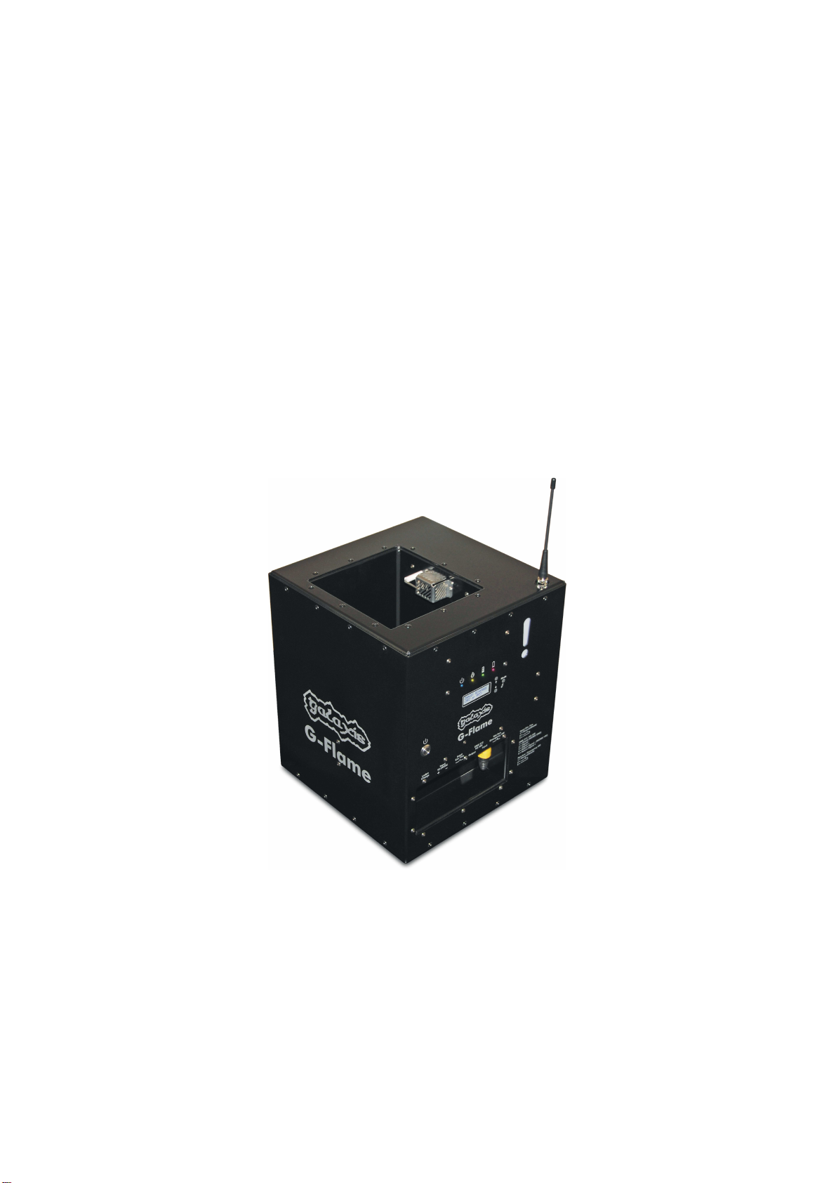
2. Application fields and intended use
The G-Flame is a versatile flame projector that can be used - depending on the fuel supply - outdoors,
on stages, in buildings or tents.