Galaxy Audio Any-Spot AS-1800 User manual

AS-1800T
WIRELESS PERSONAL MONITOR
®
Monitor
MHz
AB
CHANNEL NAME
FREQUENCY
LEVEL
SQ dB
EQ
AS-1800R


Introduction……………………………………………………………………………………..1-2
Transmitter Installation and Connections……………………...........................................…2
Installation…………………………………………………………….........................…………2
Connections……………………………………………………………......................…………2
Transmitter Controls and Functions………………………………..............………………….3
AS-1800T Front Panel……………………………………………...……………………………3
AS-1800TRear Panel………………………………………………..................……………….3
Receiver Controls and Functions………………………………......................................…..4
AS-1800R Front Panel……………………………………………….………………………….4
AS-1800R Upper Side……………………………………………..…………………………….4
Receiver Battery Installation…………………………………………....………………………4
System setup……………………………………………………...……………………………5-6
AS-1800R Transmitter Setup……………………………………..…………………………….5
AS-1800R Receiver Setup………………………………………….....………………………..6
Specification…………………………………………………………....…………………………7
Contents:

1
Power
User's Manual
Earphone
Transmitter
Antenna
System Components
System Components
AS-1800T
WIRELESS PERSONAL MONITOR
®
Monitor
MHz
AB
CHANNEL NAME
FREQUENCY
LEVEL
SQ dB
EQ
AS-1800R
Bodypack Receiver

Thank you for choosing a Galaxy Audio professional wireless in-ear monitor system. You have
joined thousands of other satisfied customers. Our years of professional experience in design
and manufacturing ensure our products' quality, performance and reliability.
1. Introduction
1. EIA-standard metal materials half - rack transmitter chassis.
2. Durable, ergonomic metal body Receiver with soft-touch controls.
3. 16MHz Bandwidth, 640 Selectable UHF frequencies / 32 Channels and True Diversity
reception for interference-resistant operation and High-visibility white LCD information
display
4. PLL (Phase Lock Loop frequency control) design ensures transmission reliability, “Noise
Lock” squelch effectively blocks stray RF.
5. Designed to provide incredible audio quality and reliable performance for artists,
broadcasters and other demanding audio environments.
2. Transmitter Installation and Connections
Installation
1. For better operation the transmitter should be at least 3ft. (1m) above the ground and at
least 3ft. away from a wall or metal surface to minimize reflections.
2. Keep antennas away from noise sources such as computer, digital equipment, motors,
automobiles and neon lights, as well as away from large metal objects.
3. Antenna are normally positioned 45° from vertical for best transmission.
4. Keep open space between the receiver and transmitter for better reception.
5. The transmitter should be at least 6ft. (2m) from the receiver.
Connections:
1. The 12V, 500mA switching power supply is designed to operate properly from any AC
power source without user adjustment. Simply connect the transmitter to a standard AC
power outlet, using only an IEC-type input cordset approved for the country of use.
Power to the unit is controlled by the front panel power switch.
2. There are two audio inputs on the rear panel: 1/L and 2/R audio INPUTS. Suitable for
an XLR balanced audio input connector and a Unbalanced 1/4” (6.3mm) input
connector. The two audio inputs simultaneous feed from two different outputs.
Use the appropriate shielded audio cable for connections between the transmitter and the
output(s) of the mixer or other audio output equipment.
Introduction
Introduction
2

AS-1800T
WIRELESS PERSONAL MONITOR
®
Monitor
MHz
AB
CHANNEL NAME
FREQUENCY
LEVEL
SQ dB
EQ
3
7
Figure A: Front Panel:
Figure B: Rear Panel:
Antenna Input Jack: BNC type antenna connector.
RF POWER Output: Two-position switch adjusts RF power output with LOW of
30mW, HIGH of 100mW.
1/L Unbalance LOOP OUT output jack: Unbalanced 1/4" (6.3mm) jack
to connect to another AS-1800 transmitter’s Balanced Input.
2/R Unbalance LOOP OUT output jack: Unbalanced 1/4" (6.3mm) jack to
connect to another AS-1800 transmitter’s Balanced Input
1/L Balanced Input Jack: XLR type connector. A standard 2 conductor shielded
cable can be used to connect the transmitter input to a balanced output on a
mixer or integrated amplifier.
2/R Balanced Input Jack: XLR type connector. A standard 2 conductor shielded
cable can be used to connect the transmitter input to a balanced output on a
mixer or integrated amplifier.
DC Power Input Jack: 12V / 500mA.
Power Switch: Press power switch
in for 3 seconds and the transmitter
readouts will light.
Monitor: Earphone
output jack.
LCD Window: Liquid Crystal Display
indicates control setting and
operational readings. See “System
setup” on page (5) for details.
1/4"
AS-1800T Transmitter Features:
UP / DOWN Buttons: Press Up or Down
arrow button, in conjunction with the Set
button, to step through menus, select
operating frequency and edit transmitter
functions.
SET Button: Use in conjunction with the Up
/ Down arrow buttons to step through
menus, choose operating frequency and
select transmitter functions.
PUSH
PUSH

Power indicator
Left and Right Channels Balanced Switch:
To balance the volume of left and right channels
for the Headphone.
Jack.
Mono or Stereo Selector Switch: If selecting Stereo,
indicator (9) lights.
Power Switch.
A: Power supply switch: When powered on,the
indicator is green.
B: Volume control: Once the receiver power is ON, adjust this
switch to control the volume of Headphone.
LCD Window: Liquid crystal display indicates
operational frequency, channel and battery
condition. The transmitter's “fuel gauge” battery
indicator displays a maximum of 4 bar segments.
When it leaves 1 bar segment, the batteries should
be replaced immediately to ensure continued operation.
Antenna Diversity Receiving Signal Strength Indicator.
AF Signal Indicator.
Stereo Indicator.
SET Button: Use in conjunction with the Up / Down arrow
buttons to step through menus, choose operating
frequency and select receiver function options.
UP / DOWN Buttons: Press Up or Down arrow button, in
conjunction with the Set button, to step through menus,
select operating frequency and edit receiver functions.
Battery Door Switch
Battery Compartment
Headphone
1
2
3
4
5
6
7
8
9
10
Wearing the Bodypack Receiver
Belt Clip: For best results, clip the receiver onto a belt by
pushing the receiver down onto the belt as far as possible.
For Guitarists: Slide the guitar strap ”through” the receiver
clip.
Changing Batteries
Expected life for two Alkaline batteries is
approximately 7 hours.
Locate the Battery Door Switch, Open the battery
door by sliding the switch. Insert 2 fresh 1.5V AA
batteries. (Alkaline type is recommended, always
replace both batteries.)
Observe correct polarity as marked inside the
battery compartment.
4
Bodypack Receiver
Bodypack Receiver
AS-1800R
AS-1800R

Select a Group and Channel:
Press “SET” button, “GROUP” will display, press or
button to select suitable frequency group number, as
shown in Diagram on the left. Then press “ SET” again ,
“CHANNEL” will display, press or to select suitable
channel, as shown in Diagram . on the left.
Note: When using multiple systems, for optimum results
set all of the systems to the same group number and
select a different channel number for each system in
that group.
Stereo/Mono Mode Selection:
Press “SET” button 3 times, “Mode Select” will display,
press or to select Stereo or Mono, as shown in
Diagram .
Locking Selection:
Press “SET” button 5 times, “LOCK SELECT” will display,
press or to select Lock or Unlock, as shown in
Diagram .
Audio Input Level Indication
Displays left and right audio input level, as shown in
Diagram .
Note: Adjust audio input levels to indicate “0” on the
loudest signals.
1
2
3
4
5
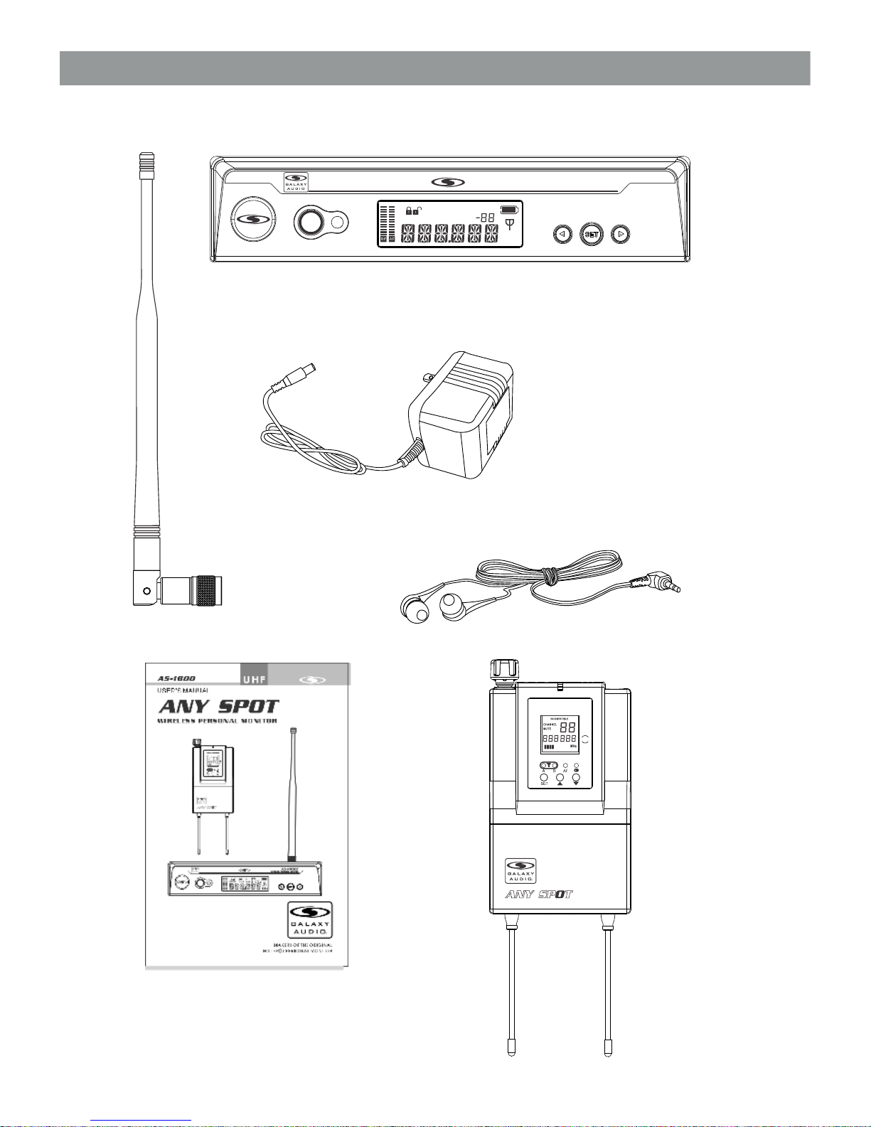
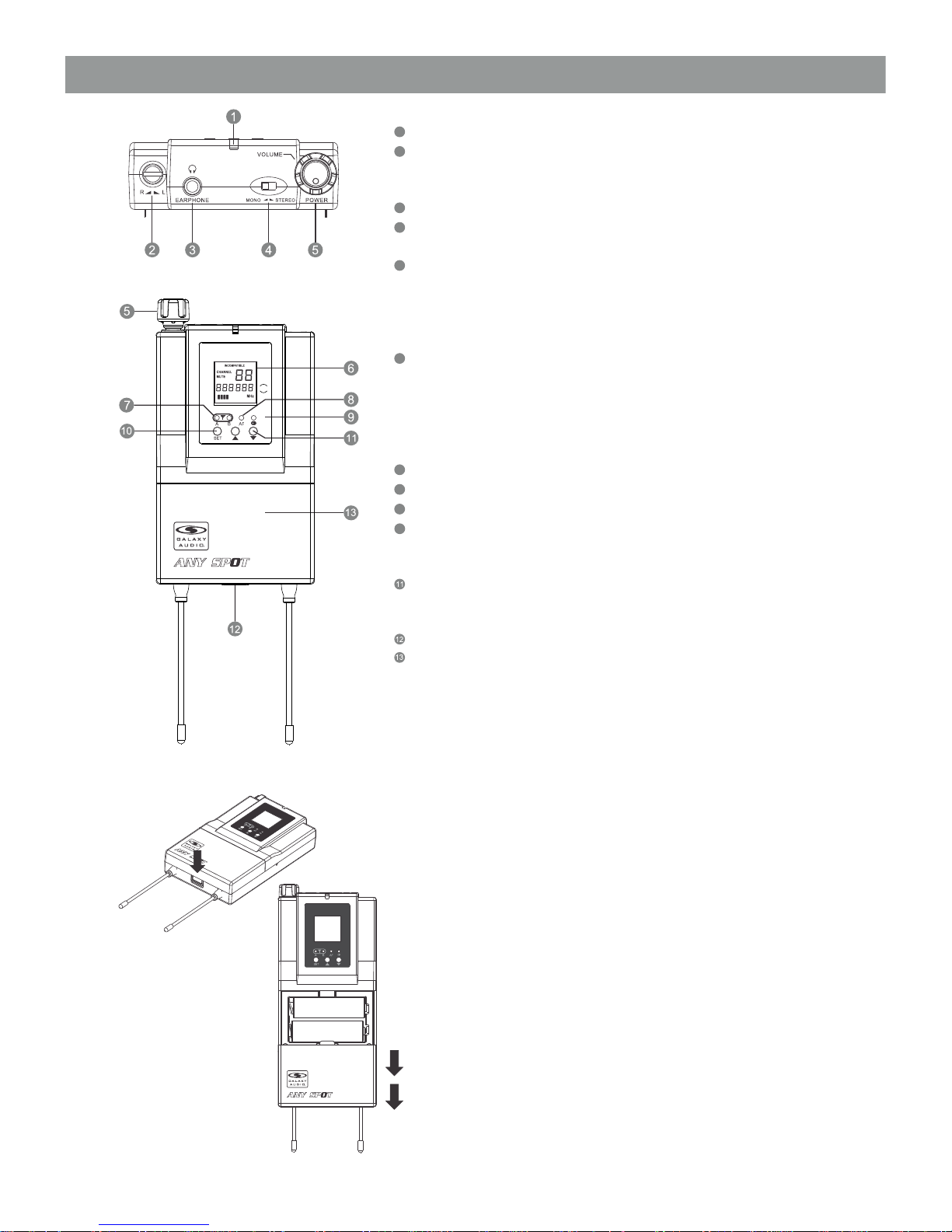
AS-1800 Transmitter Setup
5
System Setup
System Setup
1.) Turn down the AF level of the associated mixer or amplifier.
2.) Turn on the transmitter, the LCD displays the preset data.
3.) Change the frequency by Pressing </> button to change the frequency, then “SET” to confirm the
selected frequency.
4.) To enter the menu mode: Press and hold the SET button for 3 seconds to enter the edit mode, press the
< or > button once to select and set RENAME, SENSITI, LOCK, DISP, INPUT or LEVEL.
A.) RENAME: Select “RENAME”, then press the “SET” Button to enter edit mode (System pre-set name is
AS-1800), when the first number flashes, press the < or > arrow button to choose any number (0-9) or letter
(A-Z) or character. After the first number has been picked , press the “SET” button, then the second letter
flashes. Repeat till the sixth letter is programmed. Press the “SET” button on the transmitter to confirm the
desired choice.
B.) SENSITI (Sensitivity): Select “SENSITI”, then press the SET button to enter edit mode, press </> button
to select “HIGH” or “LOW”. Press the “SET” button on the transmitter to confirm the desired choice.
C.) LOCK: Select “LOCK”, then press the SET Button to enter edit mode, press the </> arrow button to
select “ON” or “OFF”, when “ON” is selected, the AS-1800T enters a lock mode, the user can not make
changes to the AS-1800T settings; When “OFF” is selected, the user can make changes to theAS-1800T
settings. Press the SET Button on the transmitter to confirm the desired choice.
D.) DISP (display): Select “DISP”, then press the SET Button to enter edit mode, press the </> arrow button
to select “FREQUENCY” (frequency), “CHAN” (channel) or “NAME”. When selecting “FREQ”, the LCD will
display the operational frequency; When selecting “CHAN”, the LCD will display the operational channel;
When selecting “NAME”, the LCD will display the user name; Press the SET Button on the transmitter to
confirm the desired choice.
E.) INPUT: Select “INPUT”, then press the SET Button to enter edit mode, press the </> arrow button to
select “MONO” or “STEREO”. When “MONO” is selected, the AS-1800T is transmitting a mono signal;
When “STEREO” is selected the AS-1800T is transmitting a stereo signal. Press the SET Button to confirm
the desired choice. (When the AS-1800T is set to transmit in Mono, Only the 2/R Input should be used )
F.) LEVEL (Squelch): Select “LEVEL”, then press the SET button to enter edit mode, press the </> button to
scroll through the available choice for the function. The squelch level is adjustable in 80 1dB steps,
providing 0dB to -80dB range. Press SET Button to confirm the desired choice.
AS-1800R
AS-1800R
AS-1800R
AS-1800R
AS-1800R
AS-1800R
AS-1800T
AS-1800T
AS-1800T

6
System Setup
System Setup
AS-1800 Receiver Setup
1.) Turn on the receiver, the LCD displays the preset data.
2.) Change the frequency by pressing the </> button to change the frequency, then
“SET” to confirm the selected frequency.
3.) To enter the menu mode: Press and hold the SET button for 3 seconds to enter the edit mode,
press the </> button to select and set SQ, LOC or P OFF.
A.) SQ (squelch): Select “SQ”, then press SET Button to enter edit mode, the squelch level
flashes to indicate editing, press the </> button to scroll through the available choice. The
squelch level is adjustable in ten 5dB steps, providing a 50dB range. Press the SET button to
confirm the desired choice.
(SQUELCH of receiver has been preset at the factory. If interference is a problem, first consider
trying a different frequency. If it is not necessary, please do not adjust the SQUELCH randomly.
This could cause unwanted interference. )
B.) LOC (lock): Select “LOC”, then press the SET Button to enter edit mode, press < or > arrow
button to select “ON” or “OFF”, When “ON” is selected, theAS-1800R enters lock mode, the
user can not use any button for any control; When selecting “OFF”, changes to theAS-
1800R can be made. Press the SET Button on the receiver to confirm the desired choice.
C.) P OFF (power off): Select “P OFF”, then press SET Button to enter edit mode, press < or >
arrow button to select “OPEN” or “CLOSE”, When “OPEN” is selected, the unit will turn off
automatically after 30 minutes if it is outside the communications service area (no signal
available ); When “CLOSE” is selected, the unit has to be turned off manual. Press the SET
Button on the receiver to confirm the desired choice.

AS-1800T Stereo Transmitter
Main Frame Size: EIA STANDARD ½ U
Channels: 32 Channels / 640 Selectable Frequencies
Frequency Stability: ±0.0005%, Phase Lock Loop frequency control
Available Frequencies : B2 538~554 MHZ
B3 554~570 MHZ
Modulation Mode: FM stereo modulation
Output Power: 30mW or 100mW
Operating Range: 300' (100M) typical (in open space)
Oscillation: PLL synthesized
Spurious Rejection <-60dBm
Maximum Deviation Range: ±68KHz
Band Width: 16MHz
S/N: >105dB
T.H.D.: <0.7% @ 1KHz
Frequency response: 45Hz~18KHz±1dB
Audio Input: Line level X 2, XLR and ¼" Combo jack
Audio Output: 6.3mm unbalanced jack X 2
Dimensions: 1.7" x 8.2" x 8.1" (44mm (H) x 209mm (W) X 206mm (D)
Weight: 2.3 lbs 1.04kg
Ø
AS-1800R Stereo
Bodypack Receiver
Channels: 32 Channels / 640 Selectable Frequencies
Frequency Stability: ±0.0005%, Phase Lock Loop frequency control
Available Frequencies : B2 538~554 MHZ
B3 554~570 MHZ
Modulation Mode: FM stereo modulation
Operating Range: 300' (100M) typical (in open space)
Oscillation: PLL synthesized
Sensitivity: 6dBµV, S/N>60dB at 25 deviation (mono)
Band Width: 16MHz
Max. Deviation Range: ±68KHz
S/N: >105dB
T.H.D.: <0.7% @ 1KHz
Frequency response: 45Hz~18KHz±1dB
Stereo Separation: 45dB (at 1KHz)
Output Connector: 3.5mm (Ø) stereo earphone connector
Output Power: 150mW at 1KHz (THD1%)
Battery: AA X 2
Current Consumption: 185mA typical
Battery Current / Life: About 7 hours
Dimension: 4.25" x 2.6" x .87" (108mm(H) X 66mm(W) X 22mm(D))
Weight: .35 lbs (.16kg)
>
7
Specifications
Specifications

AS-1800T
WIRELESS PERSONAL MONITOR
®
Monitor
MHz
AB
CHANNEL NAME
FREQUENCY
LEVEL
SQ dB
EQ
AS-1800R
PUSH
PUSH

1-800-369-7768 www.galaxyaudio.com
Specifications in this manual are subject to change without notice.
V112211
Please visit galaxyaudio.com for the latest updates
© Copyright Galaxy Audio Inc.
LIMITED THREE YEAR WARRANTY
Please visit galaxyaudio.com for the latest updates
http://www.galaxyaudio.com/warranty.php
www.galaxyaudio.com/warranty.php
www.galaxyaudio.com
Table of contents
Other Galaxy Audio Recording Equipment manuals

Galaxy Audio
Galaxy Audio Any Spot AS-900 User manual

Galaxy Audio
Galaxy Audio Any Spot AS-900 User manual

Galaxy Audio
Galaxy Audio AS-1400 User manual

Galaxy Audio
Galaxy Audio HDR2 User manual

Galaxy Audio
Galaxy Audio DSPOT DS-CP22 User manual

Galaxy Audio
Galaxy Audio RM2 User manual

Galaxy Audio
Galaxy Audio ANY SPOT AS-1400-2P User manual