Galaxy PILOT P4.5 User manual


P4.5 • P5 • Р5.1
User’s Manual
PILOT Series

P4.5 • P5 • Р5.1
User’s Manual
Part 1. Specifications and assembling Page
1. Models and specifications ……………………………………………
2. Standard features and optional equipment …………………………
3. Boat views ……………………………………………………………...
4. Boat assembling ……………………………………………………….
5. Valves operation ……………………………………………………….
6. Electric system …………………………………………………………
7. Fuel system …………………………………………………………….
Part 2. Safety and precautions
8. Recommendation signs ……………………………………………….
9. An important message ………………………………………………...
10. Certification ……………………………………………………………
11. Identification …………………………………………………………..
12. Manufacturer’s ID plate ……………………………………………...
13.Motor type, installation and operating ………………………………
14. Boat operating instructions: …………………………………………
a. Distribution of the load
b. Checklist before departing
c. Rules to observe during navigation
d. Mooring and towing
e. Lifting
f. Trailer
15. In case of accident …………………………………………………..
16. Environment ………………………………………………………….
17. Maintenance: …………………………………………………………
a. Cleaning
b. Air tightness of inflatable tube
c. Maintenance of stainless steel
d. Maintenance of aluminium, plywood seats and floor
e. Winterizing and storage
f. Regular inspections
18. Contacts and Service…...............................................................
CONTENTS Page
PILOT Series
3
4
5
6
7
9
11
12
12
13
13
13
15
17
20
20
21
22
2

PILOT P4.5 •P5 • P5.1 - are RIB models with aluminium hull and remote steering.
1. MODELS AND SPECIFICATIONS
PART 1. SPECIFICATIONS AND ASSEMBLING
Models Unit of
measure P4.5 P5 P5.1
Length
overall
c
m / ft,
inches
450 / 14’ 9” 500 / 16’ 5” 500 / 16’ 5”
Length
inside
c
m / ft,
inches
355 / 11’ 8” 410 / 13’ 5” 350 / 11’ 6”
Width
overall
c
m / ft,
inches
215 / 7’ 1” 215 / 7’ 1” 215 / 7’ 1”
Width
inside
c
m / ft,
inches
111 / 3’ 8” 111 / 3’ 8” 111 / 3’ 8”
Tube
diameter
c
m / ft,
inches
52 / 20” 52 / 20” 52 / 20”
Bare
Boat weight kg / lbs 280 / 616 370 / 814 400 / 882
Loading
cpacity kg / lbs 800 / 1760 900 / 1980 1000 / 2200
Passengers
capacity
7 8 9
Number
of
chambers
5 5 5
Engine
recommended
HP / kW 50 / 36.8 70 / 51.5 80 / 58.8
Engine
max HP / kW 70 / 51.5 100 / 73.5 100 / 73.5
Engine
weight max kg / lbs 130 / 286 180 / 396 180 / 396
Engine
shaft length inches 20”20”20”
Deadrise
on the
transom
/ Deadrise
on
the middle
deg 23°/ 28°23°/ 28°23°/ 28°
Boat
draft including
engine
weight m0,35 0,35 0,35
Tube
material
options
HYPALON,
VALMEX,TPU HYPALON,
VALMEX,TPU
HYPALON,
VALMEX,TPU
Bottom
type Aluminium
hull RIB
EN AW 5083 H111
Alu
hull thickness mm 4 5 5
Boat
design
category
CE C C C
3
All technical data are subject to change without notice. The products details and specifications may be changed
from specified herein. All the dimensions are ±3%. All the weights are ±10%

STANDARD FEATURES:
•Deep V-shaped aluminum hull with powder coating.
•Self-draining cockpit, double gutters, engine compartment, bow locker, welded
metal keel protection.
•4 lifting eyes, 2 rear and 1 bow tow eyes.
•U-shaped 5-chamber inflatable tube made of Valmex, TPU or Hypalon
materials with 5 overpressure valves and a safety rubrail and original
"GALA-JET" design rescue layer.
•Selection of pro-grade steering consoles with or without front seat - C-04P,
C-09, respectively.
•Selection of seatings for customer choice.
• «QUINTET» antiskid embossed decking.
• Stern locker for storage with a double seat (Р5.1).
•Seat S-04P, S-10, S-12 at the customer's choice.
•Two paddles, high-efficiency foot pump.
•Repair kit and manual.
OPTIONAL EQUIPMENT:
•Bow step plate with bollard and anchor roller.
•Fuel system with tank and fuel level sensor.
•Set of electrical equipment.
•Console radar mast № 1.
•Towing arch with 2 cleats & tow eye.
•Radar arch № 2 (P4,5; P5), № 3 (P5.1) at the customer's choice.
•Bow bollard.
•T-top with an additional upper mounting plate - № 1 (Р4,5; Р5; Р5.1).
•Overall cover, console/seat covers.
•Two side step panels with handles.
•Customized lettering on tube and Т-top.
2. STANDARD FEATURES AND OPTIONAL EQUIPMENT
4

3. BOAT VIEWS
5
General boat views PILOT Р4.5 and Р5:
General boat views PILOT Р5.1:

4. BOAT ASSEMBLING
Step 1:
Open the boat
Step 2:
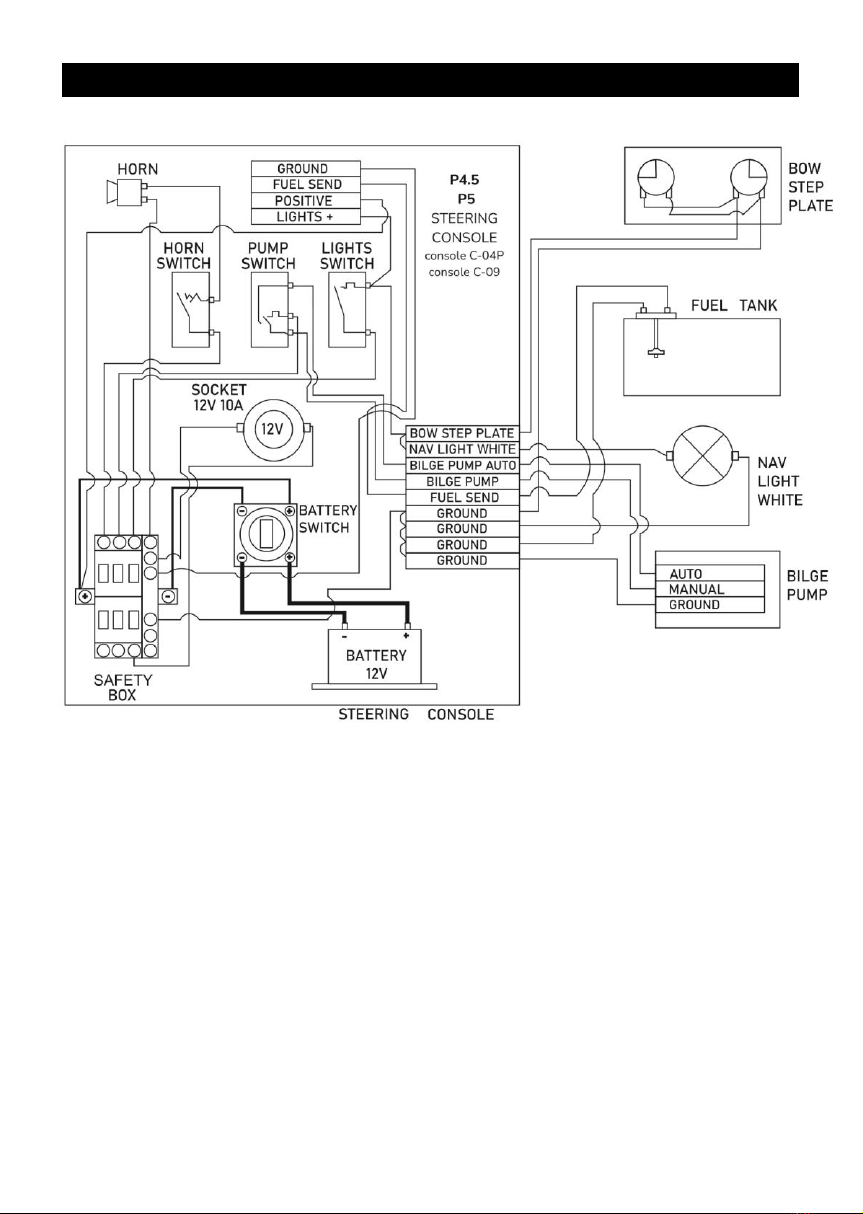
Assemble and install
steering console
Step 3:
Install outboard motor
Step 4:
Install double seat
Step 5:
Inflate the boat
- Inspect the condition of the package for and report
to your dealer if you find any damages.
- Remove all the packaging plastic and cardboard
carefully. Do not use knife.
- Check the completeness of the boat and make sure
that no any parts are missing. You must report the
missing part to your dealer immediately.
Unpack the steering console. Connect and secure the
steering cable to the steering system. Install steering
wheel. If your boat is expected to feature electric start
–install the battery tray on the deck under steering
console. Assemble and mount control box on the right
side of the console. Make sure the handle in upper
position does not touch the railing. Install the steering
console on the deck with bolts with washers and
tighten them.
Install the outboard motor following the motor user’s
manual.
Unpack the double seats and install them on the deck
with bolts with washers and tighten them.
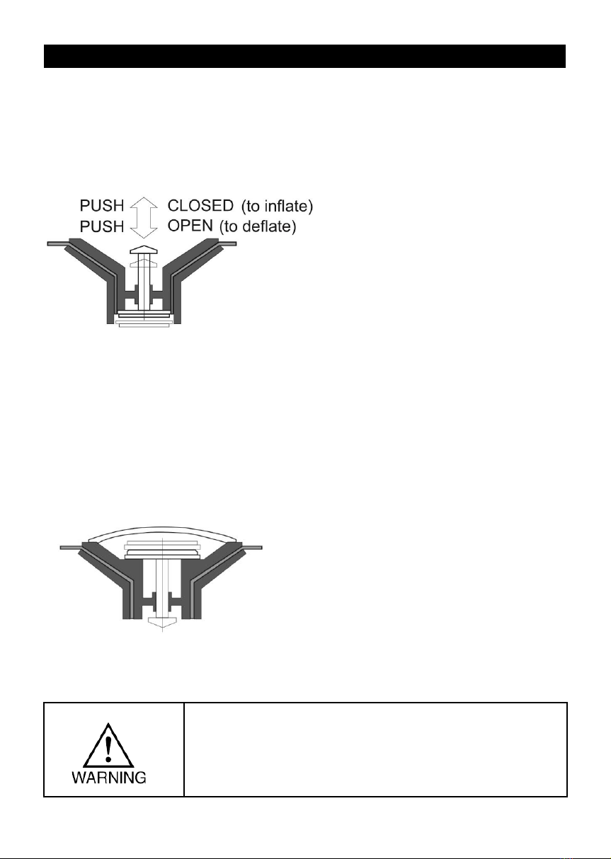
- Open the pump, connect the pump hose to the pump
onto inflation opening.
- Connect bayonet adapter of the pump hose to the valve
-Inflate the rear compartments first up to pressure
slightly below nominal, and the bow compartment
the last up to the nominal pressure. In this case the
flexible baffles in the tube will move towards the rear
compartments and equalize the pressure in all
compartments.
You may use the manometer to measure the pressure
level to ensure the best performance of the boat and
make sure that the pressure is about nominal level.
Nominal tube pressure is mentioned on Capacity Plate
IMPORTANT!!! WE STRONGLY RECOMMEND THE BOAT
ASSEMBLING AND THE OUTBOARD MOTOR RIGGING
TO BE MANAGED BY CERTIFIED BOAT DEALER ONLY
6

5. VALVES OPERATION
a) INFLATION-DEFLATION VALVE
operation:
b) OVERPRESSURE VALVE
operation:
Inflation-deflation valve has
PUSH-PUSH operating system:
Pressing the central pin the valve
Switches between OPEN and
CLOSED.
To inflate the tube put the pin to
CLOSED position (pin moves
UP). To deflate the tube put the
pin to OPEN position (pin moves
DOWN).
After inflation every valve must be
closed with the valve plug tight to
ensure airtightness of the tube.
Overpressure valve protects the
boat against unexpected pressure
increase over the maximum
working limit.
In case of any tube pressure
ncrease or overinflating the gasket
of the valve will open
automatically, release all
excessive air and bring the tube
pressure to nominal. Make sure
that the valve cup is always clean.
Check the valve operation during
boat maintenance.
OVERINFLATING AND OVERHEATING OF YOUR BOAT MAY
CAUSE THE BOAT DAMAGE. AVOID OVERPUMPING THE
BOAT, LEAVING THE BOAT NOT COVERED, USING HIGH-
PRESSURE INFLATORS. USE MANOMETER TO CHECK THE
PRESSURE IN THE TUBE REGULARLY
7

5. VALVES OPERATION
c) DRAIN VALVE operation (Р4.5; Р5):
Drain valve includes:
a) Expanding plug inside of the cockpit
with opening-closing lever, b) One-way
drain valve with elastic petal.
To drain the water from the cockpit:
•open and remove the expanding
plug from the through-hull,
•start the engine and move the boat
with speed 8-12 km/h until the
water drains out of the boat
completely,
•put the expanding plug back and
close it.
d) DRAIN VALVE operation (Р5.1):
Drain system includes:
a) two drain through-hull fittings at the
bottom of the rear compartment
wall with two expanding plugs,
b) one way drain valves on the boat
transom,
c) connecting tube.
The cockpit of the boats is self bailing.
To drain thew water in the cockpit take
out the expanding plugs and water will
drain out automatically.
For effective draining inspect drain
system regularly and make sure it is
always clean, free of debris and has no
anydamages.
a) c) b)
8

6. ELECTRIC SYSTEM
The manufacturer reserves the right to modify the boat wiring or wiring diagram without notice.
9
Electric system wiring diagram PILOT P4.5 / P5
•All models are equipped with an electric kit that includes an automatic bilge pump.
•Fuel send wiring is presented only on the boats with fuel system installed.
•To connect the engine, follow the engine's user manual instructions and rigging guide.
•Regularly inspect the condition of all electric elements and wiring, and clean or replace
elements with signs of corrosion or any damage.
•Inspect the functionality of all system features before your ride.
•To change the fuses, use only fuses with proper design and ratings.
•Protect fuses and other elements of electric system from water.
•Keep your battery disconnected with battery switch at all time when the boat is
not in use.
•Maintain your battery following the battery user's manual instructions.
•In case of smoke or insulation burning smell switch your battery off to avoid fire.
•Do not use any of electric equipment with a sign of its damage or non-proper
functioning.
•Actual wiring may be modified from shown herein at factory choice.
•Manufacturer does not allow modification of electric system without written consent.

6. ELECTRIC SYSTEM
The manufacturer reserves the right to modify the boat wiring or wiring diagram without notice.
10
Electric system wiring diagram PILOT P5.1

7. FUEL SYSTEM
11
7.2. Safety
•Never overfill your tank or spill fuel - spilling fuel into the engine or
passenger compartment can increase the risk of explosion or fire,
and spilling fuel into the water will harm the marine environment.
•Never smoke while refueling, fuel system service or inspection.
•The boat battery switch and all electric equipment on board must be
switched off during refueling, fuel system service or inspection.
•Ask your passengers to exit the boat until you're finished fueling, for
their safety.
•Never use ethanol fuel - it can cause your equipment to malfunction.
•After fueling, open any ports, hatches and doors to ventilate fumes
that may have entered your boat during the fueling process.
•Perform the 'sniff test' to check your bilges - make sure you don't
smell gasoline. Stop using the boat if you smell gas immediately.
•lnspect all elements of the fuel system regularly and do not
operate the boat with any leaks or damages of fuel system
elements.
•Do not repair the fuel system other than by authorized Dealer only.
7.1. Fuel system mounting Р4.5; Р5; Р5.1
Р4.5; Р5; Р5.1 fuel system
Fuel system includes:
• Рermanently installed fuel tank with 83 lit (P4.5; P5;P5.1) capacity
•STD type fuel sender
•Gas fill with vent
•Gas fill tray with drain
•Fill-in hose, vent hose, engine feeding hose traced to the boat transom
7.2. Fuel system mounting
The fuel tank is permanently installed in the ventilated underdeck space (Р4.5; Р5; Р5.1)
The fuel system does not include any fuel filters or other equipment, except for the EPA
system - a special development for the US market (US Environmental Protection Agency -
EPA). All additional equipment must be installed and properly tested prior to use by a
qualified third-party boat fitter dealer to ensure that the final fuel system installation and
connections meet local legal requirements and standards.

PART 2. SAFETY AND PRECAUTIONS
8. RECOMMENDATION SIGNS
Throughout this manual there are advisories of sate operation.
The symbols below are advisories relative to various types of situations
DENOTES AN EXTREME INTRINSIC HAZARD EXISTS
WHICH WOULD RESULT IN HIGH PROBABILITY OF
DEATH OR IRREPARABLE INJURY IF PROPER
PRECAUTIONS ARE NOT TAKEN
DENOTES A HAZARD EXISTS WHICH CAN RESULT IN
INJURY OR DEATH IF PROPER PRECAUTIONS ARE
NOT TAKEN
DENOTES A REMINDER OF SAFETY PRACTICES OR
DIRECTS ATTENTION TO UNSAFETY PRACTICES
WHICH COULD RESULT IN PERSONAL INJURY OR
DAMAGE TO THE CRAFT OR COMPONENTS
NOTICE:
9. AN IMPORTANT MESSAGE
1. THIS USER'S MANUAL MUST BE ON YOUR
BOAT, IN A SECURE AND EASILY
ACCESSIBLE PLACE FOR PILOT.
2. WE TAKE NO RESPONSIBILITY FOR THE
CONSEQUENCES OF ACTIONS NOT
COMPLYING WITH THE INSTRUCTIONS
DESCRIBED IN THIS MANUAL.
3. ALL THE IFORMATION HERE IS RIGHT FOR
THE TIME OF ISSUE.WE RESERVE THE RIGHT
TO CHANGE THE CHARACTERISTICS, DESIGN
OR AVAILABILITY OF BOAT MODELS , PARTS
AND ACCECCOSRIES ANY TIME.
4. CONTACT YOUR LOCAL DEALER FOR LATEST UP-
TO-DATE DETAILS, SPECIFICATIONS AND DOCUMENTS
GIVES IMPORTANT INSTRUCTIONS
12

10. CERTIFICATION
All our boats comply with ISO standard ISO6185, established by the International
Standards Organization, and with the European Directive 2013/53/EU.
11. IDENTIFICATION
12. MANUFACTURER'S ID PLATE
2
6
5
3
4
8
1
7
13
Every boat has "Craft Identification Number" (CIN), which uniquely identifies your boat and is
important for safety purpose. The CIN is marked on nonremovable metal plate, which is
affixed onto the transom area of your boat:

Тhe indications on the capacity plate give information about limitations imposed by
international regulations. Your local regulations can be different. Also these indications are
not a complete list:the security requirements (obligatory security equipment of the boat,
maximum authorized distance you can navigate from a shelter, etc.) may change according
to the country or state.
Always refer to local regulations to be informed on actual requirements.
The details of the capacity plate are:
1 - Design category (European Directive 2013/53/EU ):
Category C D
Navigation "Near the shore" "Protected water"
Wind speed (Beaufort scale) Until 6 included Until 4 included
Significant height of wave to
consider (in meters) Until 2 included Until 0.5 included
BE RESPONSIBLE, TAKE NOTICE OF THESE PARAMETERS
WHEN YOU PLAN YOUR NAVIGATION PROGRAM, AND DO
NOT PUT TO SEA IF THE CONDITIONS ARE LIKELY TO
EXCEED THESE PARAMETERS
2 - MODEL: Commercial name of the model.
3 - Maximum number of people authorized on board (adults + children) according to ISO
and DIN standards.
4 - Maximum load capacity of the boat allowed by the manufacturer and expressed in
kilograms and lbs.
5 - Maximum outboard power allowed by the manufacturer for the boat and expressed in
kilowatts and lbs.
6 - Maximum outboard weight allowed by the manufacturer for the boat and expressed in
kilograms and lbs.
7 - Nominal Pressure of the buoyancy tubes in Bars and Psi. Other parts of the boat can
require different pressures Refer to the INFLATION chapter of the Owner's Manual
Volume 2.
8 - Vessel type by ISO6185 classification.
14

13. MOTOR TYPE, INSTALLATION AND OPERATING
The maximum and recommended powers are listed in the table of technical specifications. For
smaller outboards use the tiller control. For 25HP and up we strongly suggest to use the steering
console with remotesystem.
NEVER USE MOTOR WITH POWER HIGHER THAN
INDICATED, AND MOTOR WEIGHT HEAVIER THAN
INDICATED ON THE MANUFACTURER'S ID PLATE. IT
COULD RESULT IN LOSS OF CONTROL, AND YOU
WOULD BE BREAKING THE LAW
13.1. MOTOR SHAFT LENGTH
The motor shaft length must be same as required for your boat (see boat
pecifications). Using motors with other shaft length may cause the boat damage and
will void warranty.
13.2. PROPELLER
To choose the optimal propeller your boat and its motor must be tested at sea. A lower
pitch is better for the boat either heavily loaded or used tor water skiing. A higher pitch will
increase the speed potential, when loaded light.
13.3. MOTOR INSTALLATION
Install the motor along the centerline of the boat in the middle on the mounting plate (1).
Fully tighten the clamps (2) and tighten them again after 15 minutes of running. Secure the
motor to the transom with safety cable. All motors are equipped with a security stop switch
lanyard (3). Always use it!
THE BOLTING OF THE MOTOR TO THE TRANSOM IS
SUGGESTED FROM 10HP AND HIGHLY
RECOMMENDED FROM 25 HP AND ABOVE
15

1. FOR NOT BOLTED MOTORS TO THE TRANSOM:
ALWAYS CHECK IF THE CLAMPS ARE PROPERLY
TIGHTENED BEFORE DEPARTURE AND ON THEWAY.
2. FOR OUTBOARDS WITH REMOTE STEERING UNIT:
CHECK IF ALL THE CONNECTIONS AND NUTS ARE IN
GOOD ORDER AND TIGHTENED
13.4. MOTOR ADJUSTMENTS
The motor requires an adjustment of its position in trim and height for better performance in
different navigation conditions and load distribution in the boat.
b) Motor trim:
The motor must be positioned so that the axis of the propeller is parallel with the water
surface. For better performance it can be adjusted either manually or with power trim, if the
motor is equipped with it.
Motor tilted inwards too near the
transom: the boat will bow down.
Optimum position: axis of the propeller is
parallel with the water surface.
Motor tilted outwards too far from the
transom: the boats will porpoise.
1. MAKE ANY MODIFICATIONS OF THE MOTOR ONLY
WHEN THE MOTOR IS SHUT OFF.
2. FOR ANY INFORMATION ABOUT MOTOR ITSELF
REFER TO THE MOTOR’S MANUAL
а) Motor height
For different makes of motors, even inside
the same type of shaft, the length of the
shaft can vary. It is necessary to add a
shim to ensure correct height.
Correct motor height:it may vary from 0
to 30mm clearance between keel line and
anti-cavitation plate of the motor. Check the
motor manual for exact instructions.
Motor adjusted too high : propeller
aeration may occur with loss of forward
thrust (capitation).
16

14. BOAT OPERATING INSTRUCTION
Evenly distribute the load. (For example, fixing the fuel tank on the
front can help to offset the weight of the outboard).
a) Distribution of the load
1. A BAD DISTRIBUTION OF THE LOAD CAN
DESTABILIZETHE BOAT AND MAY RESULT IN A
LOSS OF CONTROL.
2. THE BOAT REACTS MORE ROUGH WHENLIGHTLY
LOADED.
3. BE PARTICULARLY CAREFUL WHEN YOU
ACCELERATE OR CHANGE DIRECTION.
4. ADJUST LOAD DISTRIBUTION AND TRIM WHEN
NAVIGATION CONDITIONS OR WAVES DIRECTION
CHANGE.
b) Check-list before departure:
GET REQUIRED INFORMATION AND INFORM OTHER
PASSENGERS:
1. GET INFORMED on local regulations and hazards
related to water activities and boat operation.
2. CHECK weather forecast, local currents, tides and
wind conditions.
3. ADVISE someone on land of time you plan to be back.
4. EXPLAIN basic boat operation to all passengers.
5. BE SURE that one of your passengers can operate the
boat in case of emergency.
6. LEARN how to determine the distance you can cover
with a full fuel tank. Always be sure you have enough
fuel to reach a shelter.
CHECK THE GOOD WORKING OF THE BOAT AND
EQUIPMENT:
1. CHECK inflation pressure.
2. INSPECT the valve caps. Remove the bailer plug.
3. CHECK the tightening of the motor clamps. For not
bolted, secure the engine with a safety lanyard.
4. TOP OFF fuel and oil level.
5. CHECK the secure and correct installation of fuel tank.
6. BE SURE motor is not in gear before starting.
7. CHECK the load is evenly distributed.
8. CHECK that required safety equipment Is on board:
a. One personal flotation device per person;
b. The foot-pump, paddles or oars, repair kit;
c. The boat papers and your boating license;
d. Lights are required if operating in dark.
17

•Be responsible: do not neglect the safety rules.
•Learn to always keep control of your boat.
•Always operate with courtesy andrespect.
•Respect local regulations and practices.
•Near the shore, navigate in the designated boating areas.
•Always be sure that you can reach a shelter rapidly.
1. WEAR PERSONAL FLOTATION DEVICE (PFD)
2. ALWAYSUSE THE STOP SWITCHLANYARD: wear it around
your wrist or affix to yourclothes.
3. NO ALCOHOL / DRUGS BEFORE OR WHILE
OPERATING YOUR BOAT.
4. DO NOT EXCEED THE AUTHORIZED NUMBER OF
PERSONS OR WEIGHT.
5. MAKE SURE YOUR PASSENGERS REMAIN SEATED
ON SEATS OR ON THE FLOOR. AVOID SEATING ON
TUBES.
6. NO BOW RIDINGAS IT IS ILLEGALAND
EXTREMELY DANGEROUS.
7. BE ESPECIALLYCAREFUL WHEN DOCKING: Arms and
legsmay be injured if they are outside theboat.
8. KEEP CLEAROF SWIMMERS AND DIVERS: Alwaysavoid
areas where divers/swimmersare in the water. Keep a sharp
lookoutespeciallywhen operatingnear beaches and launch
sites. Shut off the motor when operating near someonein the
water. The Alpha flag indicatesproximity of divers.You MUST
stay at a gooddistance(minimum50 meters).
9. AVOID SHARP TURNS AT HIGH SPEEDS: You could get
ejected from the boat.
10. DO NOT makea brutalchangein directionwithoutadvising
passengers.
11. NO SPEEDING OR RACING! Driver must keep
reasonable speed to avoid any boat stabilityloss.
12. BATTERY:
a. Avoid sparks and open flames near battery. It may explode.
b. Keep battery poles protected from any shortcut or
contact with any metalthings.
c. Turn off the engine when inspectingor servicing the
battery.
d. Never keep battery close to fuel tank, filleror fuel system
elements.
13. AVOID any contactof the inflatable tube with any sharp objects
or aggressive liquids or chemicals.
14. INSPECT AND MAINTAIN STEERING SYSTEM: an
improperly maintained system may fail, causing suddenloss
of control.
18
c. Rules to observe during navigation:

15.AVOID THE RISKS OF EXPLOSION OR FIRE
HAZARDS : Ensure your fuel system is in a good
with no leaks or smell, and maintain itproperly.
16.AVOID SMOKING ON BOARD.
17.IF FUEL HAS SPILLED ON THE FLOOR: wash off with
water. Stop operating the boat if you discover any fuel
leak or fuel smell until you find and fix theproblem.
d) Mooring and towing:
•MOORING: use the buoyancy tubes' lateral D-rings. When moored, the self-bailers
should remain open to drain the rainwater.
•TOWING: fully inflatable boats should always be towed using a bridle. Use the 2 lateral
D-rings (fixed on the buoyancy tubes) made for this purpose. For rigid inflatable boats
(RIB), use a single line attached to the mooring ring.
1. Towing must be done at low speed (not more then 10
km/h) and in goodweather conditions with nowaves.
2. Towing boat must be supervisedat all time oftowing.
To lift boat and place it on davits, use the factory installed lifting eyes only, or have them
installed by your Dealer if the boat is not equipped. Use only certified and rated lifting slings,
appropriate for your boat and motor weight.
e) Lifting the boat:
1. NOBODY ON BOARD WHENLIFTING.
2. WHEN LIFTED, THE BOAT MUST BE EMPTY (NO
EQUIPMENT) AND TIPPED TOWARD THE REAR WITH
OPEN BAILERS.
f) Trailer and davits system use:
•The trailers size and carrying capacity should correspond to your boat size and
weight. Do not use too big or too small trailer for your boat.
•Always prefer trailer / davits system with bolsters / banks with large contact spot
to rollers. Do not use the trailers / davits system with rollers only.
•The boat must be properly inflated. Leave the self-baileropen.
•Haul the boat onto the trailer using the bow eye.
•Lift the engine shaft down and fix it to the support provided on a trailer. Do not trailer
or store the boat on davits without proper engine support on the trailer.
•Tie down the boat with straps, using bow, lateral and rear eyes for that.
•Close and secure all hatches and doors on the boat. Cushions must be secured or
taken away to prevent the loss.
•Do not trailer the boat with the cover, which is not designed for transportation.
19
This manual suits for next models
2
Table of contents
Other Galaxy Boat manuals
Popular Boat manuals by other brands

Gumotex
Gumotex K1 owner's manual

Cruisers Yachts
Cruisers Yachts 520 Express Series owner's manual

Boston Whaler
Boston Whaler 230 Vantage owner's manual

Dougherty
Dougherty Everglades 223 CC 2012 owner's manual

Bavaria Yachts
Bavaria Yachts 34 Cruiser Manual for owners and skippers

Aquaglide
Aquaglide FIGURE 8 owner's manual