Galcon Gal 2 Way User manual

G2W –Gal 2 Way
Installation and Operation Instructions
Version 1.0
July 2012

G2W –Gal 2 Way –Installation and Operation Guide
About this Manual
This manual contains important information about the system components, installation process, and
operation protocols of the Gal2Way system. Make sure to carefully read all of the information contained
in this manual and keep this manual in a safe place for future reference as necessary.
Contact Us
Galcon
Kfar Blum 12150, Israel
Tel: 972-4-6900222
Fax: 972-4-6902727
E-mail: [email protected]om
Visit us at: galconc.com

Table of Contents
1Introduction.......................................................................................................................... 7
Technical Overview ...................................................................................................................7
2System Components ............................................................................................................. 9
Field Units................................................................................................................................9
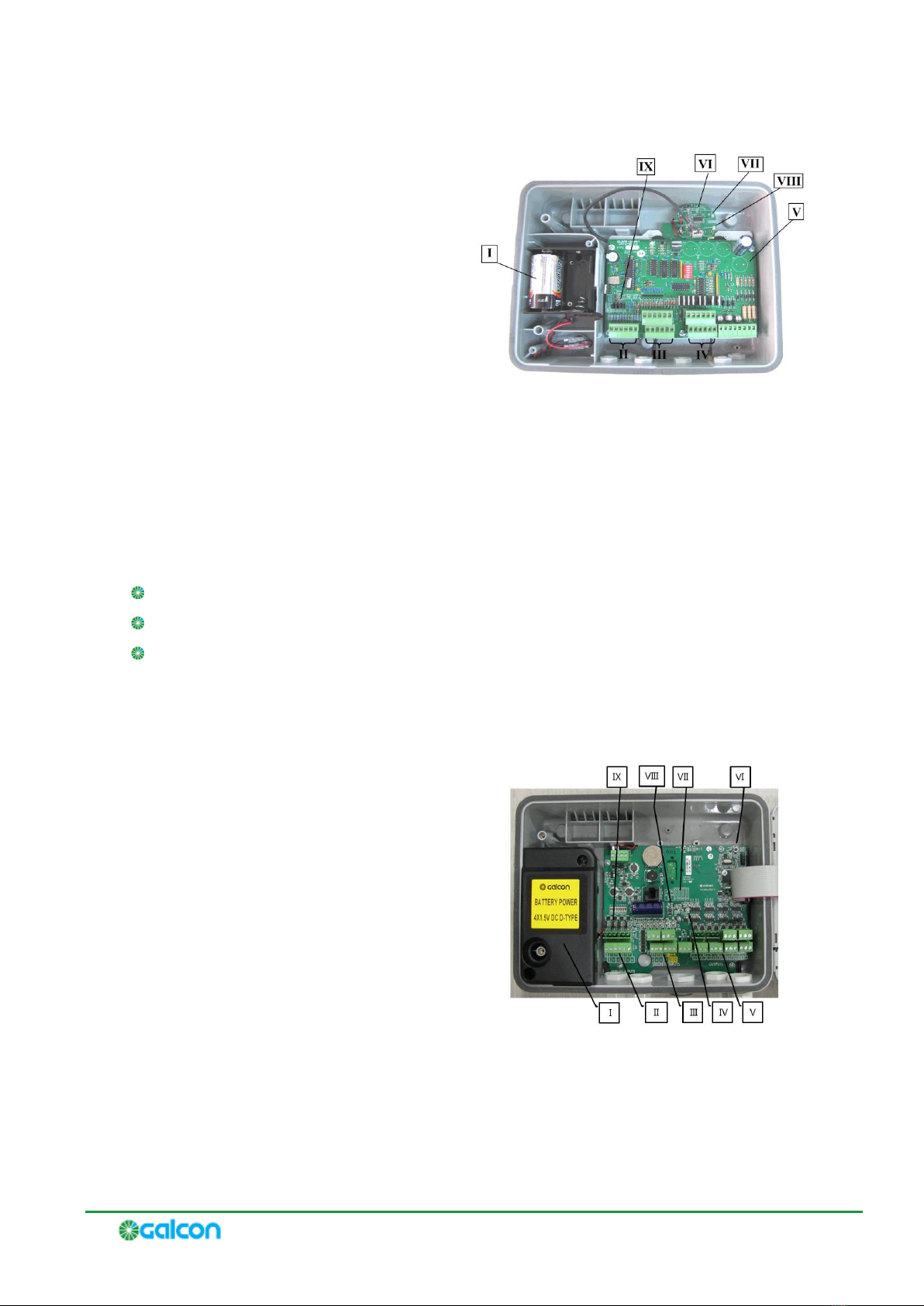
Galcon RTU Field Unit Features .........................................................................................9
G2W4 and G2W8 Field Unit Features ............................................................................... 10
Field Units Power Supply ................................................................................................11
Field Units Connection ...................................................................................................11
Repeater (Relay)..................................................................................................................... 11
Repeater Connections .................................................................................................... 11
Concentrator .......................................................................................................................... 11
Concentrator Connections ..............................................................................................12
Concentrator Main Features ............................................................................................ 12
Radio INT Adaptor Card (AC0117).............................................................................................12
Radio INT Adaptor Card Main Features ............................................................................. 13
3Registering System Components......................................................................................... 15
Concentrator Programming Buttons...........................................................................................15
Registering Field Units .............................................................................................................15
Registering Repeaters..............................................................................................................16
Viewing the List of Registered Field Units and Repeaters ..............................................................17
4Installing the G2W System ................................................................................................. 19
Pre-Installation Planning ..........................................................................................................19
Installing the Concentrator....................................................................................................... 19
Connecting the Concentrator to an External Power Supply............................................................ 20
Connecting the Concentrator to the Controller via RS-232 Connections ..........................................21
Installing Field Units ................................................................................................................ 21
Installing Repeaters ................................................................................................................22
5Performing Communications Diagnostics Tests................................................................... 25
Performing the Communications Diagnostics Test for all Field Units and Repeaters Simultaneously from
the Concentrator ........................................................................................................... 25
Performing the Communications Diagnostics Test for One Field Unit or Repeater from the Concentrator
...................................................................................................................................26
Performing the Communications Diagnostics Test from One Field Unit or Repeater ..........................27
Performing the Communications Diagnostics Test from One G2W4 or G2W8 Field Unit.....................27
Viewing Communications Strength from the Controller................................................................. 28
Enabling Communications Strength Display in the Controller...............................................28
6Configuring Field Units and Repeaters ................................................................................ 31
Modifying the Default Field Unit Configuration Settings in the Concentrator .................................... 31
Modifying the Configuration Settings for Individual Field Units from the Concentrator ...................... 32
Deleting Field Units or Repeaters from the Concentrator Registry ..................................................32

G2W –Gal 2 Way –Installation and Operation Guide
4
7Operating Gal2Way 4 and Gal2Way 8 Field Units ................................................................ 35
Viewing the Communication Status and Serial Number ................................................................35
Viewing the Galileo ID Number .................................................................................................35
Viewing the Battery Status .......................................................................................................35
Testing Output Ports................................................................................................................ 36
Verifying the Connection to Discrete Input Devices......................................................................36
Viewing the Analog Input Device Signal Levels............................................................................36
8Converting the Galileo Controller to the G2W System ......................................................... 37
Installing Radio INT Adaptor Cards ............................................................................................37
Defining the Number of Units in the System ...............................................................................37
Assigning Adaptor Card Slots for Field Units in the System ...........................................................38
ASafety Instructions for Installing Antennas ........................................................................ 41

G2W –Gal 2 Way –Installation and Operation Guide
5
List of Figures
Figure 1: Galcon 8489 RTU Features................................................................................................. 10
Figure 2: G2W 4 / G2W 8 Features ................................................................................................... 10
Figure 3: Concentrator Main Features ............................................................................................... 12
Figure 4: Radio INT Card Components .............................................................................................. 13
Figure 5: Concentrator Buttons ........................................................................................................ 15
Figure 6: Installing the Concentrator ................................................................................................ 20
Figure 7: Galcel-to-Adaptor Connection............................................................................................. 21
Figure 8: Double-Wire Cable Connections to Communication Adaptor ................................................... 21
Figure 9: Affixing the Unit to a Wall .................................................................................................. 22
Figure 10: Affixing the Unit to a Pole ................................................................................................ 22
Figure 11: Analog Inputs Setup Window............................................................................................ 28
Figure 12: Maximum Active Elements Definition Window ..................................................................... 38
Figure 13: RTU Definition Window .................................................................................................... 39


1 Introduction
The Gal2Way system, also known as the G2W system, is a radio system which is used to control and
monitor field units which are far away from the Galileo controller, utilizing latch outputs, as well as
analog and discrete inputs.
The Gal2Way system is another great addition to the Galcon Ag line of products.
Technical Overview
The G2W system consists of the following components:
Galileo Controller
Concentrator.
Repeaters.
Field units. The G2W system supports the following types of field units:
Galcon RTU.
G2W4.
G2W8.
Communication between these components is performed by two-way radio communication through
antennas which are connected to each component via RF cables.
G2W operates at MHz frequency, which is a free frequency (ISM).
For more detailed information, refer to System Components on page 9.


2 System Components
The G2W system consist a number of main components:
Field units Installed in the field next to the valves, the field unit transmits the states of the various
inputs to the controller and gets commands from the controller through the concentrator.
Repeaters Used as intermediate stations between the units and the concentrator in cases of where
direct communication is not possible, such as when the field unit is more than 2 km from the
concentrator, or when communication is blocked by obstacles.
Concentrator
to all the field units via radio communication, and returns the various inputs of the field units to the
controller.
Galileo controller Controls the irrigation system according to its programming and the field
conditions.
Field Units
The G2W system supports the following types of field unit:
Galcon RTU.
G2W 4.
G2W 8.
Field units are intended for outdoor use, operating at an ambient temperature range of -10o C to +50o C,
and at a maximum relative humidity up to 100%. The Ingress Protection of the field units is IP54.
Galcon RTU Field Unit Features
The Galcon RTU field units have the flowing input and output ports:
4 x 3 wire DC latch output ports.
8 x Discrete input ports.
3 x Analog 4 -20 mA / 0 -10 V input ports.
The analog input ports can operate at a voltage range of 0-10 V, or a current range of 4-20 mA. To define
the operation setting for each input port, move the jumper (Item IX in Figure 1) according to the jumper
diagram on the circuit board.

G2W –Gal 2 Way –Installation and Operation Guide
10
I. Battery compartment.
II. Analog input ports (4-20 mA / 0-10 V).
III. 6 X Discrete input ports.
IV. 3 X Wire 18 V DC Latch output ports.
V. Galcon RTU card as IO card.
VI. Radio INT adaptor card.
VII. Green/Red LED.
VIII. Registration button.
IX. Jumper and circuit diagram.
Figure 1: Galcon 8489 RTU Features
G2W4 and G2W8 Field Unit Features
The G2W 4 and G2W 8 Field Units have the flowing input and output ports:
4/8 x 18 V wire DC Latch output ports.
6 x Discrete input ports.
3 x Analog 4 - 20 mA / 0 - 10 V input ports.
The analog input ports can operate at a voltage range of 0-10 V or a current range of 4-20 mA. To define
the operation setting for each input port, move the jumper (Item IX in Figure 2) according to the jumper
diagram (Item VII in Figure 2) on the circuit board.
I. Battery compartment.
II. 3 x Analog inputs 4-20 ma/0-10 V.
III. 6 x Discrete inputs.
IV. Green/Red LED.
V. 4/8 x 18 V DC Latch outputs (depending
on unit type).
VI. Reset button.
VII. Diagram.
VIII. Registration button.
IX. Jumpers.
Figure 2: G2W 4 / G2W 8 Features

G2W –Gal 2 Way –Installation and Operation Guide
11
Field Units Power Supply
The field units are powered by four 1.5V D-size alkaline batteries, which are inserted into the battery
compartment. The field units can alternatively be powered by an external solar panel and charged
batteries or an internal battery. Contact Galcon to request these alternative components.
Note: Galcon RTU field units do not supply power to the connected sensors. When
connecting sensors to the analog inputs or when transmitting data to the digital inputs you
must supply an external source of power for them.
Field Units Connection
The field units can be connected to two antenna types in various combinations in order to achieve
variant communication transmission strengths. Connect each field unit to its antenna(s) with RF cables.
Do not bend the cables below a radius of 30 cm. Always keep a 60 cm distance between any two
antennas.
The various combinations below are listed according to increasing communication transmission strength:
Single 916-CW-HW antenna.
Two 916-CW-HW antennas.
916-CW-HW antenna & FG9023 antenna.
Two FG9023 antennas.
Repeater (Relay)
The repeater unit is used when the communication between a field unit and the concentrator is weak, or
when the field units are installed in locations where obstacles interfere with radio communication
between the field units and the concentrator.
The repeater is designed for installation in the field without the need for an external power source. For
this purpose, it includes both a solar panel and charged batteries.
Repeater Connections
Connect the repeater unit to two FG9023 antennas with RF cables. Do not bend the cables below a
radius of 30 cm. Always keep 60 cm distances between antennas.
Concentrator
The concentrator acts as the system manager. The concentrator transmits, via radio communication, the
commands to all the field units, and returns the various inputs of the field units to the
controller. The concentrator is connected to RF antennas and cables. The concentrator is equipped with
a backup battery which lasts for at least 24 hours.

G2W –Gal 2 Way –Installation and Operation Guide
12
The concentrator can be installed in one of two ways:
Installed close to the controller, at a distance of not more than 10 meters, using direct
communication (RS-232).
Installed at a distance of not more than 30 meters, using an RS-485 adaptor.
The concentrator is intended for outdoor use, operating at an ambient temperature range of -10o C to
+50o C, and at a maximum relative humidity up to 100%. The Ingress Protection of concentrator is IP54.
Concentrator Connections
Connect the concentrator to two FG9023 antennas with RF cables. Do not bend the cables below a radius
of 30 cm. Always keep 60 cm distances between antennas.
Concentrator Main Features
Figure 3: Concentrator Main Features
I. Green Led –Indicates a connection to a power
supply.
II. Orange Led –Indicates a malfunction, or that
the backup battery is in use.
III. Display screen.
IV. Programming buttons. (Refer to Concentrator
Programming Buttons on page 15 for detailed
information.)
Radio INT Adaptor Card (AC0117)
The I/O adaptor card (AC0117), known as the Radio INT card, enables the controller to perform
communication between the controller and the concentrator.
Note: The card does not supply power to the concentrator.

G2W –Gal 2 Way –Installation and Operation Guide
13
Radio INT Adaptor Card Main Features
Figure 4: Radio INT Card Components
I. LED indicators for normal card operation.
II. LED indicators for communication with the CPU.
III. LED indicators for communication with the concentrator.
IV. Communication indicator connector to the concentrator.


3 Registering System Components
All the field units and repeaters in the system need to be registered in the concentrator. This registration
process is performed on the concentrator; there is no need for any registration process on the controller.
Connecting or disconnecting the controller will not affect the registration process.
Notes:
It is recommended to position all the field units and repeaters near the concentrator
while performing registration. This maximizes the communication strength between the
units and facilitates successful registration.
Upon performing registration, each field unit and repeater unit downloads its default
configuration settings from the default values defined in the concentrator. You may
want to modify these default settings in the concentrator before performing
registration. For more information, refer to Configuring Field Units and Repeaters on
page 31.
Concentrator Programming Buttons
Confirmation.
Figure 5: Concentrator Buttons
Browse forward in menus.
Browse backward in menus.
Go back to main menu, or Exit.
Go back to previous menu.
Off.
Registering Field Units
1. On the concentrator, perform the following:
a. Press until is displayed on the screen, and press to select it.
b. Enter technician code 9999. The concentrator emits four beeps and requests confirmation. Do
not change the technician code.
c. Press until DEVICESis displayed on the screen, and press to select it.

G2W –Gal 2 Way –Installation and Operation Guide
16
d. Press until is displayed on the screen, and press to select it. The
message ENROLL NOW or ENTER ID XX-XXXXflashes on the screen.
2. On the field unit you are registering, hold down the registration button (see Figure 1 or Figure 2)
until the red LED turns on. Release the registration button. The station number and the Galileo
number flash on the screen (for example: SO1: Galcon RTU, GALILEO NUM: 05).
3. On the concentrator, press to confirm registration. The concentrator emits four beeps and the
enrollment message stops flashing.
4. To register additional units, perform the following on the concentrator:
a. Press . The message is displayed on the screen.
b. Press . The message ENROLL NOW or ENTER ID XX-XXXXflashes on the screen.
c. Repeat steps 1 through 3 to register an additional field unit.
Repeat these sub-steps until you have registered all the field units.
5. After you have registered all the field units, press to end the registration process and exit to the
main menu.
6. Press to confirm the registration. The message DEV UPDATINGis displayed on the screen.
The concentrator emits four beeps and returns to the main display screen.
7. Perform a communications diagnostics test on the registered field units. Refer to Performing
Communications Diagnostics Tests on page 25.
Registering Repeaters
1. On the concentrator, perform the following:
a. Press until is displayed on the screen, and press to select it.
b. Enter technician code 9999. The concentrator emits four beeps and requests confirmation. Do
not change the technician code.
c. Press until DEVICESis displayed on the screen, and press to select it.
d. Press until is displayed on the screen, and press to select it. The
message - flashes on the screen.
2. On the repeater unit you are registering, hold down the registration button (see Figure 1 or Figure 2)
until the red LED turns on. Release the registration button. The station number and the Galileo
number flash on the SO1: Gal2Way 2 GALILEO NUM: 09
3. On the concentrator, press to confirm registration. The concentrator emits four beeps and the
enrollment message stops flashing.
4. To register additional units, perform the following on the concentrator:
a. Press . The message is displayed on the screen.
b. Press . The message - flashes on the screen.

G2W –Gal 2 Way –Installation and Operation Guide
17
c. Repeat steps 1 through 3 to register an additional repeater unit.
Repeat these sub-steps until you have registered all the repeater units.
5. After you have registered all the repeater units, press to end the registration process and exit to
the main menu.
6. Press to confirm the registration. The message is displayed on the screen.
The concentrator emits four beeps and returns to the main display screen.
7. Perform a communications diagnostics test on the registered repeaters. Refer to Performing
Communications Diagnostics Tests on page 25.
Viewing the List of Registered Field Units and Repeaters
You can optionally view the list of field units and repeaters which are registered to the concentrator.
To view the list of registered field units and repeaters:
1. Press until is displayed on the screen, and press to select it.
2. Enter technician code 9999. The concentrator emits four beeps and requests confirmation. Do not
change the technician code.
3. Press until DEVICESis displayed on the screen, and press to select it. The MODIFY
DEVICESoption is displayed.
4. Press .
5. Press to browse through the list of field unit and repeater types. When the type you want to
view is displayed, press to select it.
6. Press to browse through the list of registered field units or repeaters of the type you selected.
Optionally, press for a displayed field unit or repeater to view detailed configuration
information about it, including the station number and Galileo controller ID number.
7. Press to exit to the main menu, and press to confirm. The message is
displayed on the screen. The concentrator emits four beeps and returns to the main display screen.


4 Installing the G2W System
Pre-Installation Planning
Before installing the components of the Gal2Way system, make sure to examine the installation
environment to determine the best locations for installation.
You must make sure to install components above obstructions which may interfere with the RF
transmissions between components. All components must be installed such that there is line-of-sight
between all component antennas.
Verify that there is a direct line-of-sight between the location of the unit and the location
of the .
Make sure that the distance between the field unit and the concentrator does not exceed 2 km.
Field unit antennas are to be installed on poles which are not less than 2 m high. Verify that there are
no obstructions which are more than 2 m high between the field unit and the concentrator.
If there is a significant obstruction between a field unit and the concentrator and no better location
can be found, you may be able to install a repeater (relay) to serve as an intermediary.
For the repeater, you should find a location which has line-of-sight, without significant obstructions,
and is within 2 km of both the concentrator and the field unit.
Notes:
In order to achieve the maximum results with the fewest repeaters, place the repeaters
in locations which support the maximum number of units. The system can support up to
four repeaters.
The system does not support chains of repeaters.
Installing the Concentrator
The appropriate location for installing the concentrator is determined according to the communication
type used:
When direct communication (RS-232) is used, the installation should be next to the controller, at a
distance of up to 10 m.
When using an RS-485 adaptor, the installation can be further away, at a distance of up to 30 m.
The concentrator should be positioned so that the communications and voltage cable will reach the
controller.
Affix the concentrator to the wall by inserting screws through the holes in the aluminum plate at the
back of the box.

G2W –Gal 2 Way –Installation and Operation Guide
20
Figure 6: Installing the Concentrator
Connecting the Concentrator to an External Power Supply
The process of connecting the concentrator to a power source depends on whether you are installing a
DC or an AC unit:
DC-operated Concentrator Connect a power supply of 12V DC to the correspondingly labeled
connector.
AC-operated Concentrator Connect the supplied power supply unit.
Note:
power supply of 9V 700mA AC
-The concentrator includes an internal backup battery which lasts for at least 24
hours.
Note:
The concentrator should be located within shelter for direct, initial
Protection from effects of the weather
Table of contents