GALILEI Viessmann Tecto CI2 Series User manual

01.02.2021
Cod. 80006300a - GB - VR
Read carefully and keep for future reference
DOC. 1 di 2
USER MANUAL
Tecto CI2

30.03.2020
Cod. 80005760 - GB
Dear customer,
Thank you very much for your choice!
We wish you a profitable and successful use with this refrigerating cabinet. Please read this manual carefully before
using the unit. These instructions will provide you with all the necessary information to guarantee a safe, effective, and
long-lasting use of this unit.
Read this manual carefully before using the unit
Please pay the greatest attention to the following instructions and guidelines, as well as to the pictograms and their
meanings. The warnings included in this manual have been categorized as follows
WARNING information for the correct and effective use of the unit.
DANGER notices relevant to potential hazards for people.
ATTENTION notices related to potentially hazardous situations for objects and/or for the unit.
CAUTION!
Please consider the User Manual as an integral part of the unit.
The manual should be kept within reaching distance for both the use and maintenance personnel.
In case the unit is resold, make sure to provide the new owner with this manual.
Keep the Manual in good condition for the whole life of the unit.
Keep the manual in good condition; in the event that it is damaged or lost, ask the manufacturer for a new copy.
THANK YOU!

01.02.2021
Cod. 80006620a - GB
CONTENTS
1. For your safety 5
1.1 General provisions for the user 5
1.2 General provisions for the maintenance personnel 5
1.3 Residual hazard 6
2. General data and features 8
2.1 Description and technical features 8
2.2 Nomenclature 8
2.3 Cross sections
2.4 Front Views 10
2.5 Maximum load 11
2.6 Noisiness 11
2.7 Weight of the refrigerated cabinet 11
3. The rating plate 12
4. Transportation and handling 14
4.1 Transportation and handling 14
4.2 Reception and storage 14
5. Setting up the unit 15
5.1 Positioning the refrigerated cabinet 15
5.2 Unpacking 16
5.3 Feet/supports adjusting 16
5.4 Cleaning before starting 17
5.5 Electric connection and power up 17
6. oading and using the unit 18
6.1 Preserving the displayed products 18
6.2 Provisions for loading the refrigerated cabinet 18
6.3 Temperature setting 1
6.4 Defrost 1
6.5 Correct use of the unit 1
6.6 Service/Self service conversion 20
7. User’s maintenance 21
7.1 General recommendations 21
7.2 Scheduled maintenance calendar 21
7.3 Cleaning the front glass 22
7.4 Cleaning the acrylic glass parts 22

01.02.2021
Cod. 80006620a - GB
7.5 Cleaning the internal bottom surface of the casing 23
7.6 Cleaning the defrost water tank 23
7.7 Cleaning the condenser 23
7.8 Cleaning the condenser with the removable filter 24
8. Dixell XR50CX control panel 25
8.1 Description 25
8.2 Switch the unit on and off 25
8.3 Normal conditions of operation 25
8.4 User interface 26
8.5 Set-point (working temperature) 27
8.6 Defrosting 27
8.7 Lights, switching on/off 27
8.8 Alarm warnings 28
8. Programming the controller 2
9. Wurm CRA control panel 30
.1 Description 30
.2 Switch the unit on and off 30
.3 Normal conditions of operation 30
.4 User interface 31
.5 Set-point (working temperature) 32
.6 Defrosting 32
.7 Lights, switching on/off 32
.8 Alarm warnings 33
. Programming of the controller 34
10. Anomalies and remedies 35
10.1 Anomalies and remedies 35
11. Spare Parts and Warranty 37
11.1 Technical Support and Spare Parts 37
11.2 Warranty 37
11.3 EPREL database 37
12. Dismantling and disposal 38
DOC. 2 di 2 (Enclosure)
Installation Instruction
Note: the document Installation Instruction is integral part of the User Manual

5 01.02.2021
Cod. 80005780a - GB
Units running with flammable refrigerant R290 (Propane)
The final user and the personnel in charge of maintenance and/or technical interventions should read and
properl understand these instructions before using the unit.
1.1 General provisions for the user
The units running with R290 are identified by a specific tag applied on the base sidewall. The type and quantity
of the refrigerant are given on the serial number plate of the unit.
Caution! o not damage the refrigerating circuit.
Caution! o not keep explosive substances (such as aerosol cans) with flammable propellant inside the unit.
Caution! o not use mechanical devices or other systems to speed up the defrost process, unless they are
recommended by the manufacturer.
Caution! o not use electric appliances in the display area, unless they are recommended by the manufacturer.
Caution! o not exceed the load limits of display decks and shelves, as given in the section “General ata and
Features”.
Caution! o not obstruct the ventilation openings along the external perimeter of the unit.
Caution! In case the cable or the plug are damaged, call the maintenance personnel for the replacement.
1.2 General provisions for the maintenance personnel
R290 refrigerant is a class A3 ANSI/ASHRAE gas. It is highl flammable and it ignites very easily. It can in-
stantly burn with explosive effects.
The R290 refrigerant dispersed in air may lead to a fire risk or explosion in presence of free flame and/or
sparks generated by electric devices.
Maintenance and servicing are exclusively reserved to qualified personnel with a professional certificate, is-
sued by a certified body that certifies the following:
- the expertise to work on refrigerating circuits operating with R290 as a refrigerant.
- the expertise to handle safely type HC refrigerants (i.e. Hydrocarbon, to which R290 belongs) according to the
EN13313:2011.
Maintenance shall be carried out considering the risks mentioned above: do not use electric tools and open
flame.
Components which require replacement: use only original spare parts which are certified to operate in refrigera-
tion circuits working with R290.
1. For our safet

6 01.02.2021
Cod. 80005780a - GB
The refrigeration circuit is hermetically sealed; therefore, repairing interventions on the circuit are not possible
without breaking the vacuum.
In the event that vacuum breaking is needed for carrying out maintenance operations, follow the following provi-
sions:
• The operation can not take place inside the store or indoors.
• The unit must be moved to a suitable environment and guarantee the adequate safety. Work outdoors or alter-
natively in a properly ventilated environment; in this case, the ventilation shall be able to disperse outside (in the
atmosphere) any possible refrigerant losses.
uring the installation, maintenance or dismantling operations, all the possible ignition sources (smoking includ-
ed) must be strictly avoided.
If it is necessary to carry out welding or brazing operations or other operations which cause the generation of
heat and high temperatures; strictly follow the requirements of this section. It is recommended that you do the follow-
ing:
• Remove the refrigerant
• Flush the circuit with inert gas
• Evacuate
• Flush the circuit again with inert gas
• Open the circuit and carry out the maintenance
1.3 “Residual hazards”
Residual hazards are risks that remain even after all possible protection measures are taken in the design phase and
the unit is fitted with additional protection guards. This information chapter is an integral part of the measures adopted
by the designer to minimize residual hazards and it is meant for the store operators. Therefore, every operator must
know the residual risks of the unit to prevent possible accidents.
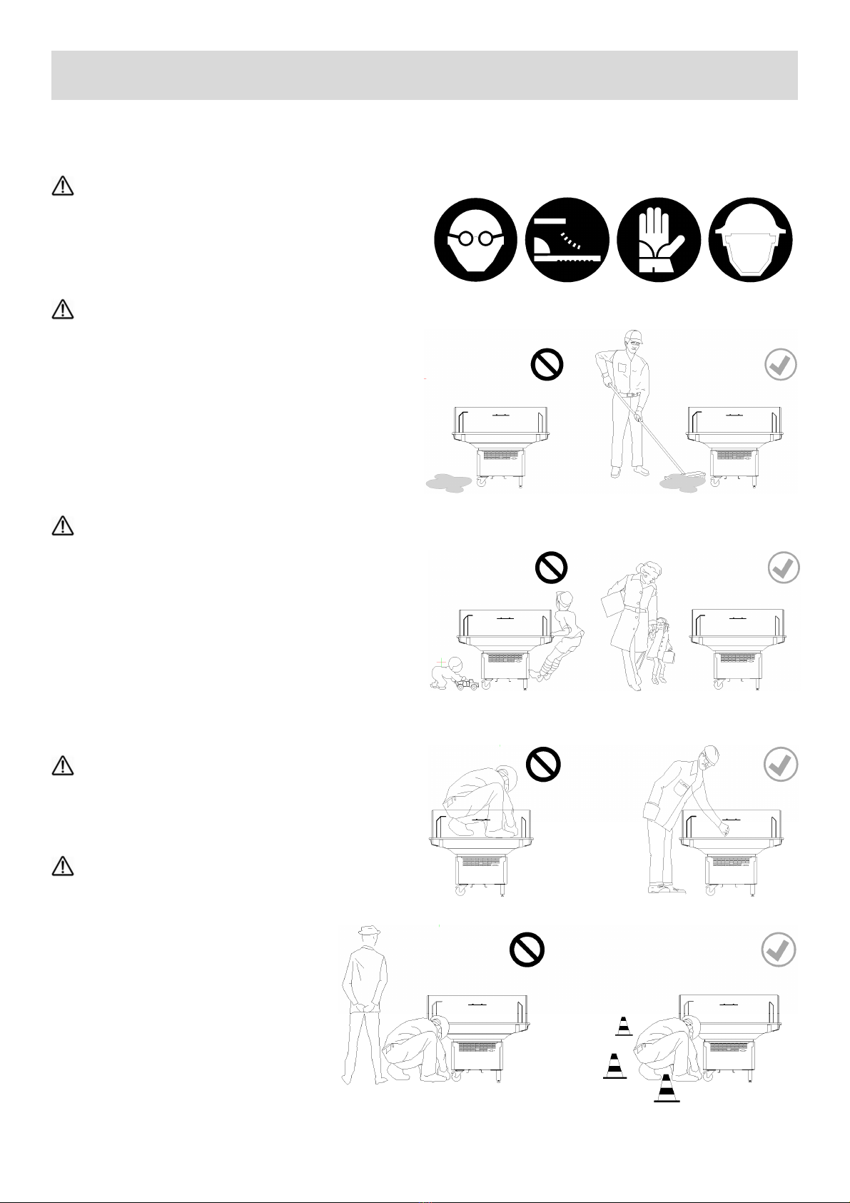
General measures to reduce hazards:
• Implement the surveillance of the market and intervene in the case of non-compliant use by users (i.e. custom-
ers).
• Manage the unit properly according to the provisions contained in this manual. Periodically check the integrity
of the unit and its visible parts. In case of doubt, contact the assistance service.
• Wear adequate PPE while cleaning, maintaining and loading the goods (i.e. work clothes, protection gloves and
glasses, safety shoes, helmet).
• o not remove the protection and safety systems. Check for the integrity of all the plates and tags of the refrig-
erating cabinet.
• o not modify the refrigerated cabinet and make sure that original spare parts are used in the event of a tech-
nical intervention.
1. For our safet

7 01.02.2021
Cod. 80005780a - GB
Risks
Protruding and raised parts, edges.
In maintenance and loading phases, there may be a gen-
eral hazard of bruising the hands and arms, head and
legs. Wear suitable workwear and PPE.
Wet floor
In case of severe environmental conditions, the conden-
sate water re-evaporation automatic system might not be
able to discharge water completely so some water might
overflow. Risks of a fall and bruising. Therefore, limit the
area and dry it. If possible, restore the correct environ-
mental conditions (see the chapter 5 titled
“Commissioning”).
Unsupervised children
Children have a reduced perception of danger. If they are
not supervised, children might be at risk. o not allow chil-
dren to play or run near the refrigerating cabinet. o not
allow them to climb on, or hang from, the external struc-
ture, or grab potentially dangerous parts (e.g. glass). Gen-
eral risk of bruising on the hands and arms, head and
legs. Intervene promptly and call for the attention of their
supervising adults.
Access to the refrigerated cabinet
o not climb on the cabinet. Overturning risk, risk of falls
and bruising.
Maintenance operations
In the case of maintenance , limit the working area with
special signals. anger of falling in the sur-
rounding area of the refrigerating cabinet,
danger of objects falling. Intervene in the
case that these provisions are not followed.
1. For our safet

8 01.02.2021
Cod. 80006330a - GB - VR
2.1 Description and technical features______________________________
Self-service refrigerated cabinet with forced air circulation and built-in condensing unit, suitable for displaying and mer-
chandising pre-packed food such as salami, dairy products, deli, fruit and vegetables. Equipped with endwalls, display
decks in powder-coated galvanized steel, front 2 mm diameter bumper-rail in stainless steel, electronic control panel
with safety circuit breaker as the main switch, evaporator with thermostatic expansion valve, automatic defrost, auto-
matic system for the re-evaporation of the defrost water. Base in powder-coated galvanized steel equipped with level-
ling feet (swivelling wheels as optional for the Tecto CI2...7 /9 ...D/T, standard for Tecto CI2 5 ). Foamed body multi-
plexable side by side with other refrigerated cabinets. Available in the version with sliding doors (optional) and without
condensing unit for installation in remote plants. Available in the version with one, two or three intermediate glass
shelves.
2.2 Nomenclature _____________________________________________
2. General data and features
Tecto CI2. 70
Tecto CI2. 90
Tecto CI2...50
1 Front base panel
2 Electronic controller
3 Levelling feet
4 Side bumper-rail
5 Endwall
6 Front bumper-rail
7 Control panel
8 Defrost water tank
9 Swivelling wheels with brakes
1 Cable-wrap bracket
11 Condensing unit
12 Aluminium fascia
13 “Self-service” glass
14 Air intake baffle
15 Display deck
16 Fan panel
17 Evaporator
18 Insulated carcass
19 Intermediate shelf
2 Load limit mark
21 Acrylic glass top canopy
22 Acrylic glass perforated back-side panel
23 Thermopane external back-side panel

9 01.02.2021
Cod. 80006330a - GB - VR
2.3 Cross sections ____________________________________________
2. General data and features
Tecto CI2 50 D Tecto CI2 50 T Tecto CI2 50
Tecto CI2 70 D Tecto CI2 70 T Tecto CI2 70
Tecto CI2 90 D Tecto CI2 90 T

10 01.02.2021
Cod. 80006330a - GB - VR
2.4 Front views_______________________________________________
2. General data and features
Tecto CI2 50 D Tecto CI2 50
Tecto CI2 70 D Tecto CI2 70 D
Tecto CI2 70 T Tecto CI2 70
Tecto CI2 90 D Tecto CI2 90 T
Tecto CI2 50 T

11 01.02.2021
Cod. 80006330a - GB - VR
2.5 Maximum load ____________________________________________
Maximum load accepted for Tecto CI2 model is 9 kg/m2 on the display decks, 4 kg/m2 on glass intermediate shelves
and 2 kg/m2 on acrylic top canopy. The load must be distributed evenly on the display deck.
2.6 Noisiness ________________________________________________
The noisiness of the refrigeratied cabinet can vary according to the environmental conditions (temperature and humid-
ity in the store) and the cleanliness of the condenser. Our tests recorded a maximum noise level of 54 dB(A) at a dis-
tance of 1 m from the cabinet.
2.7 Weight of the refrigerated cabinet ______________________________
The following table gives the weight of the refrigerated cabinet including endwalls and bumper, accessories not includ-
ed. The standard version of packaging is considered i.e. pallets and protective film.
Weight without packaging (kg) Weight with packaging (kg)
Model \ Length mm 65 937 125 1875 65 937 125 1875
Tecto CI2 5 D 1 11 - - 12 135 - -
Tecto CI2 5 T 1 5 12 - - 125 145 - -
Tecto CI2 5 Q 115 13 - - 125 145 - -
Tecto CI2 7 D 13 145 2 - 155 17 22
Tecto CI2 7 T 14 155 - - 165 18 -
Tecto CI2 7 Q - 175 - - - 185 -
Tecto CI2 9 D - - 155 - - - 18 -
Tecto CI2 9 T - - 17 - - - 195 -
9 kg/m2
4 kg/m2
4 kg/m2
2 kg/m2
2. General data and features

12 01.02.2021
Cod. 80005800a - GB
3.1 The rating plate____________________________________________
The rating plate is normally positioned near the electrical switchboard or in the tank for multideck or island versions.
The plate displays all the information to identify the unit as well as the technical specifications to install the unit proper-
ly.
3. Rating plate
RoHS
The refrigerated cabinet is subject the WEE European irec!ve 2002/96/EC (for plug-in refrigerated cabinets only)
The unit complies with the RoHS European irec!ve 2002/95/EC (for plug-in refrigerated cabinets only)
Please always provide this infor-
mation when a spare part is ordered.
Before performing the electrical
connection, make sure that the unit fea-
tures match the power supply network
of the place where the unit is to be in-
stalled.
1
2
2
4
5
6
7
8
9
10
11
12
1
14
15
16
17
18
19
20
21
22
2

13 01.02.2021
Cod. 80005800a - GB
Meaning of the rating plate fields
1Model and length of the refrigerated cabinet
2Serial number, code and/or configuration number (if any)
Year of manufacture
4
Climate class, it gives the proper environmental conditions in which the unit operates properly
– The unit is suitable for operating in an environmental temperature of 25° C and a relative humidity of 60%
4 – The unit is suitable for operating in an environmental temperature of 0° C and a relative humidity of 55%
5
Temperature class of the unit; it indicates the category of the products that can be preserved in the refrigerated
cabinet:
L1: suitable for the preservation of frozen food or ice-cream
M0: suitable for the preservation of fresh products such as meat and poultry
M1: suitable for the preservation of fresh products such as meat and poultry
M2: suitable for the preservation of fresh products such as salami and dairy products
H: suitable for the preservation of fresh products such as fruit and vegetables
S: suitable for the preservation of products with a special classification
6
Maximum power absorbed by the unit, with all required accessories installed, operating in the temperature
class for which the units were built (given by the temperature class)
7
Power absorbed during defrost; includes the electric heater (if present) and all the other electric devices operat-
ing during the defrost cycle, such as controllers, fan motors, lighting etc.
8Rated supply voltage, number of phases and frequency to which the cabinet must operate.
9Electrical power absorbed, rated voltage and current of other installed electric devices (if any).
10 Electrical power absorbed, rated voltage and current of the defrost heaters (if any)
11 Electrical power absorbed, rated voltage and current of the demisting heaters (if any)
1 Type and quantity of used refrigerant
14 It indicates the kind of lamination device. CT = capillary tube. TVX = thermostatic valve
15 Net volume of the additional refrigerant storage (if any)
16 Refrigerated display area available to display the goods
17 Maximum operating pressure inside the refrigeration circuit of the unit
18 Rated current absorbed by the unit in normal operating conditions
19 Rated current absorbed by the unit at the compressor starting phase (starting current)
20 Model of condensing unit or compressor installed
21 Electrical power absorbed, rated voltage and current of the lighting system (if any)
22 Electrical power absorbed, rated voltage and current of the fan motors (if any)
2 Electrical power absorbed, rated voltage and current of the condensing unit
12 ID name in the EPREL database
3. Rating plate

14 01.02.2021
Cod. 80005810 a- GB
4.1 Transportation and handling __________________________________
In order to be transported, the cabinet is delivered on a Europallet with standard dimensions (120 x 80 cm), and fixed
by means of proper fixin plates. Unloadin must be carried out by means of a forklift (see chapter “2.7 wei ht of cabi-
net”), usin the desi nated handlin points indicated in the below picture. The available packa in are: Europallet with
protective film (standard), Europallet with carton box (options), Europallet with wood crate (options). The types of
packa in depends on the model of cabinet and on the client’s request.
We remind you that the use of forklift is exclusively allowed to authorized personnel who has been properly cer-
tified as “forklift operator”. Durin unloadin , placement and installation of the cabinets the use of proper protective
equipment is required (protective loves and eyeware, safety shoes).
Only when the cabinet is placed on the final point of installation inside the market, remove the protectin film
and plates. For this operation refer to chapter “5.2 Unpackin ”.
The packa in is composed by recyclable materials which shall be separated and disposed of in accordance
with waste disposal re ulation in force in the country where the disposal occurs.
4.2 Reception and storage ______________________________________
Durin the take-over of the cabinet from the conveyor, verify the packa in conditions. If there are evident dama es,
take a photo raph of the dama ed parts and si n with reservation the delivery documentation. Once the dama e is
checked promptly inform the conveyor, the insurance company and your supplier.
The cabinet shall be stora ed in an indoor ambient with a temperature not exceedin 55 °C. Avoid the exposure
of the cabinet to direct sunli ht which could deform plastic materials, dama e electrical components and make the
removal of the protective film difficult.
4. Transportation and handling
Pallet and cardboard Pallet and protective film Pallet and protective film

15 01.02.2021
Cod. 80005820a - GB
5.1 Positioning the refrigerated cabinet _____________________________
For unloading and handling the cabinet with a forklift, we recommend using the marked handling points as given in
this manual.
We remind you that the use of forklift is exclusively allowed to authorized and properly trained personnel. Dur-
ing the unloading, positioning and installing phases, the personnel should wear suitable personal protection equipment
i.e. protective gloves, glasses and reinforced shoes). Place the unit, still packed, in the final installation position
in the store. Please see the sections below.
The cabinet cannot be used outdoors. Check the environmental conditions in which the unit will be installed
and match the climate class given on the unit’s identification plate i.e climate class 3, max room temperature of 25°
C, R.H. 60 %). Higher levels of temperature and/or relative humidity can cause higher energy consumptions and poor-
er performances, consequently shortening the shelf-life of the displayed products.
Avoid the exposure of the cabinet to direct sunlight, don’t place the unit close to heat sources such as ov-
ens, heating radiators, high-intensity lighting systems and any other heating source.
The unit should not be subject to air flows with a speed higher than .2 m/sec. It is highly recommended
that the unit is positioned far from doors, windows and air conditioning grids.
Make sure there is a frequent change of air in the room where the unit is operating even when the store is
closed.
The refrigerated cabinet base is designed to guarantee a proper ventilation of the condensing unit; therefore do
not obstruct the air intakes by placing any type of materials along its external perimeter
To avoid the condensation formation keep a space of 5 cm from the thermopane back-side panel.
5. Setting up the unit

16 01.02.2021
Cod. 80005820a - GB
5.2 Unpacking______________________________________________________
The unit is delivered in a packaging made of a Europallet and a cardboard box see Chapter 4 “Transportation and
handling”). Once the cabinet is placed on the installation point, make sure that the packaging is integral and undam-
aged. If there is any damage caused by transportation, take a photo of the damage and report it to the supplier.
Wear suitable PPE i.e. protective gloves, glasses and safety shoes). Use strong scissors i.e. electrician’s scis-
sors or bolt cutters) to cut the strings. Remove the strings, lift the cardboard box and remove it.
Remove the plastic strings that fix the cardboard box to the wooden Europallet. Caution! The strings are tight-
ened and, when they are cut, there can be a “whip effect” that can be hazardous. Proceed with caution and do not cut
the strings while standing in front of them.
Packaging is mostly made of recyclable materials wood and cardboard and small amounts of plastic film). Do
not dispose of them in the environment! Please refer to the local regulations in force for the correct disposal of the
materials and deliver them to a suitable disposal centre.
Remove the screws that fix the metallic brackets which block the feet and wheels see images below). Now it is
possible to remove the unit from the Europallet and place it on the floor.
5.3 Feet/supports adjusting __________________________________________
Before starting the unit for the first time, adjust the feet so that the unit is stable and perfectly horizontal. Lev-
elling will guarantee the proper drainage of the defrost water as well as a noiseless and smooth operation of the unit.
Adjust the levelling feet if any) and check the horizontal alignment by using a spirit level on the length and the width of
the refrigerated cabinet.
5. Setting up the unit

17 01.02.2021
Cod. 80005820a - GB
5.4 Cleaning before starting
Before connecting the unit to the power supply, remove the protective films and clean both the internal and external
surfaces of the refrigerated cabinet, in particular the display decks. It is recommended that you use lukewarm water
and neutral detergents (pH 6÷8).
Do not use hoses connected to the water system to clean the unit. Do not use direct or indirect water jets or
pressurized cleaning machines i.e. high pressure washers).
Do not use alcohol, abrasive pads or solvents to clean the unit. After cleaning, dry the parts immediately with a
soft cotton cloth. For further details and information about cleaning, please see Chapter 7 “User’s maintenance”.
5.5 Electric connection and power up __________________________________
The power supply to which the cabinet is going to be connected must comply with the regulations in force in the
country where the unit is installed. The frequency and voltage rating of the power supply must correspond with the
values given on the identification plate of the refrigerated cabinet. Before switching on the unit, make sure that the
voltage rating matches the one required and is within the allowed tolerance limits ±10%).
It is mandatory to ground the refrigerated cabinet. Efficient grounding is essential for safety.
Upstream of the socket, it is recommended to have the installation of an omni-polar power isolator switch, with
air gap between the contacts of at least 3 mm. This measure is to be considered mandatory if the connected load ex-
ceeds 1000W, or if the unit is connected directly to the power supply without using a plug e.g. cabinet without con-
densing unit and connected to an external refrigeration unit). The power isolator switch should be a magnetothermal
switch with high sensitivity differential circuit breaker.
Do not use time-based devices to switch on-off. Do not connect the unit to cyclical on and off switching circuits.
Do not use extension cords, adaptors and multiple sockets. Do not bend, twist, stress or squeeze the cord and
avoid it touches hot surfaces or sharp edges.
If the cable is damaged, ask the Technical Support or a qualified technician to replace it. Use an original spare
part.
If the socket does not match the plug, ask a qualified technician for a replacement of the socket.
Before inserting the plug into the socket, make sure that the main power switch of the unit magnetothermal
switch) is in OFF position. Insert the plug into the socket and switch on the unit. If the unit is not used for a long time,
switch off the power switch and pull out the plug.
5. Setting up the unit

18 01.02.2021
Cod. 80006370a - GB
6.1 Preserving the displayed products _____________________________
The refrigerated cabinets are designed to guarantee the display of pre-cooled products. Products come from
refrigerated places such as refrigerated warehouses or cold-rooms at a temperature as close as possible to the ideal
one. The quality of the displayed product is strictly related to the “cold chain” which is maintained during the various
passages in logistics. Products that are not properly pre-cooled and are positioned in the refrigerated cabinet
decrease the unit performance and can also damage other displayed goods. Therefore, it is essential that goods are
not kept, even temporarily, in non refrigerated places that may raise the product temperature. When the product is
delivered, the supplier should place it immediately in a cold-room or in the refrigerated cabinet. eat, in particular,
must be kept in refrigerated rooms throughout the whole manufacturing process (sectioning, boning, slicing, packag-
ing, etc). If the operations last more than 2 minutes, make sure that the meat is brought back to a cold room to re-
establish the ideal temperature.
The working temperature of the refrigerated cabinet is displayed by the digital thermometer installed in the
cabinet (usually it is close to the air-intake grill). The values given by the electronic controller or other devices (if any),
cannot be considered as a reference of the temperature of the displayed product because the temperature probes are
placed according to technical criteria that don’t directly give the preservation temperature.
6.2 Provisions for loading the refrigerated cabinet _______________________
For a proper and effective running of the unit, avoid the displayed products from obstructing the correct circula-
tion of the refrigerated air. Furthermore, it is important to observe the load limit, indicated by the red line
__▼__▼__ when stacking the products. The goods exceeding the load limit would not be properly refrigerated and
air turbulence would be created with negative effects on unit performances (massive formation of frost inside the
evaporator) and a deterioration of the displayed products’ preservation.
It is recommended not to place the product on the air-intake grills. This would reduce the refrigerated air-
flow inside the cabinet, and consequently it would cause a rise in temperature.
6. Loading and using the unit

19 01.02.2021
Cod. 80006370a - GB
6. Temperature setting ________________________________________
Setting-up working parameters: for adjusting the “set-point” temperature and the other parameters, see the in-
structions of the control panel included in this manual. When setting up the set-point, make sure that the resulting tem-
perature in the cabinet matches the temperature class of the cabinet and/or the displayed product. Setting up a tem-
perature that is too low may obstruct the evaporator and create an excessive formation of frost.
6.4 Defrost __________________________________________________
The units are equipped with an automatic system for the cyclic defrost of the evaporator. This system is
managed by the electronic controller of the control panel. Defrost parameters are pre-set at the factory according the
needs of each unit. In particular cases, it may be necessary to manually start a defrost cycle by using the electronic
controller (see the instructions about the electronic controller given in this manual). anual defrost will have to be acti-
vated whenever a loss or a reduction of air flow is detected at the air-discharge grill. This condition occurs when the
evaporator is clogged by frost that prevents air from circulating properly. If there is massive or a rapidly developed for-
mation of frost inside the evaporator that requires frequent manual defrost operations, it means that the environmental
conditions where the unit is working are not suitable or that the goods are not properly positioned in the unit.
During closing time or holidays, it is recommended to use “night blinds” or “night covers” (both of them are op-
tional accessories). This measure provides a substantial reduction of energy consumption and a better preservation of
the products.
.
6.5 Correct use of the unit____________________________________________
The unit cannot be used by people, including children, whose physical, sensorial or mental capacities are im-
paired, or by people who are not properly trained, unless they are supervised by a person responsible for their safety
who has explained them the correct and safe use of the unit.
The unit is used in places open to public. ake sure children are supervised to avoid that they play with the
unit.
It is striclty forbidden to use the unit, or part of it, improperly.
Avoid to overload display decks of the unit as well as its shelves and top canopy. Follow the loading limits given
in this manual (see chapter 2 “General data and features”).
For units working with R290 as refrigerant, which is flammable, refer to the safety warnings given in the chap-
ter “For your safety” at the beginning of this manual.
6. Loading and using the unit

20 01.02.2021
Cod. 80006370a - GB
6.6 Positioning of intermediate shelves _____________________________
It is possible to tilt and/or lift the intermediate shelves by using the different shelf holder positioned on the side-
walls.
To change the layout of the glass shelves proceed as follows:
• Unscrew the fixing screw of the shelf holders [5]. Extract the glass shelf [6] removing it from both sides (Fig. 1)
• Remove the shelf holder [6] from the sidewall. (Fig. 1)
• To tilt the glass shelf (Fig. 2) insert the shelf holder in the sidewall holes as given in the following table:
• To lift up the glass shelf (Fig. ) insert the shelf holder in the sidewall holes as given in the following table:
• Reposition the glass shelf by sliding it inside the shelves holder, then tighten the shelf holder screw.
6. Loading and using the unit
Combination A-1A-2A-3A-4B-3
Angle 0° 7° 14° 21° 7°
B-2
0°
C-3
0°
B-4
14°
C-4
7°
Combination A-1B-2C-3
Angle 123
A
B
C
4
3
2
1
Fig.Fig.2
6
5
Fig.1
A
B
C
4
3
2
1
This manual suits for next models
8
Table of contents
Other GALILEI Commercial Food Equipment manuals
Popular Commercial Food Equipment manuals by other brands

Welbilt
Welbilt Manitowoc Indigo installation guide

Welbilt
Welbilt Frymaster UHCTHD Original Instructions Installation, Operation and Maintenance Manual

Welbilt
Welbilt Convotherm OES mini 6.06 user manual

NUVU
NUVU Pro-8 owner's manual

Num'axes
Num'axes EYENIMAL user guide

Goldmedal
Goldmedal 6501 instruction manual

Goldmedal
Goldmedal 2343 instruction manual

GGM gastro
GGM gastro PEP44TC Instruction, use and maintenance manual

Avantco
Avantco 360CPT40 user manual

True
True TRCB-52 installation manual

Porkka
Porkka Cold Series Installation and operation manual

Roller Grill
Roller Grill VHC 1000 Use and installation manual