Galileo MODC03B003 User manual

1
MANUAL
INPUT MODULE
INTRINSICALLY SAFE
IMGALILEO
MODC03B003
12/2020
Ver:06
Schedule Drawing- Do not change without certification agency /Notified Body approval.
2
MANUAL
INPUT MODULE
INTRINSICALLY SAFE
IMGALILEO
MODC03B003
12/2020
Ver:06
Schedule Drawing- Do not change without certification agency /Notified Body approval.

3
Foreword
Information in this document is subject to change without notice.
Galileo Technologies reserves the right to change or improve its
products and make changes to the content without obligation to
notify any person or organization of such changes or
improvements. ©2020 Galileo Technologies. All rights reserved.
Except as expressly provided herein, no part of this manual may
be reproduced for any purpose without the express prior written
consent of Galileo Technologies
GALILEO Technologies
Av. General Paz Provincia 265
(B1674AOA) Sáenz Peña
Buenos Aires
Argentina
Tel.: +54 11 4712 8000
Fax: +54 11 4712 6003
www.galileoar.com

4
CONTENT
1. Introduction…………………………………………………………………………………………..5
1.1 Contents…………………………………………………………………………………………………………..5
1.2 Symbols Used…………………………………………………………………………………………………..5
2. Products type…………………………………………………………………………….………….6
3. Intended use………………………………………………………………………………….……...7
3.1 Technical Specification…………………………………………………………….….………….….......7
3.2 Technical Data ………………………………………………………………………………………………...7
4. Mounting…………………………………………………………………………………………......8
5. Equipment Installation and operation.…………………………………….………......9
5.1 Connection to the supply…………………………………………………………………………………9
5.2. Equipment operation……………………………………………………………………………………10
6. Fuse operation…………………………………………………………………………………....11
7. Cleaning and decontamination………………………………………………………......11
8. Equipment maintenance and service……………………………………………………12
8.1. Disconnecting circuits……………………………………………………………………………………13
8.2. Removing the device…………………………………………………………………………………….13
9. Handling and storage, and transportation...………………….……………..………14
10. Dimensions…………………………………………………………………………………………14
11. Datasheet…………………………………………………………………….………………….…15
12. Electrical/Electromechanical drawings ………………………………………………18
13. Electrical wiring drawings ………………………………………………………………….19
14. Customer Service……………………………………………………………………………….20
5
1. Introduction
1.1 Contents
This document contains information that you need in order to use your
product throughout the applicable stages of the product life cycle. These
can include the following:
• Delivery, transport, and storage
• Mounting and installation
• Operation
• Maintenance
• Troubleshooting
• Dismounting
1.2 Symbols Used
This document contains symbols for the identification of warning
messages and of informative messages.
Warning Messages
You will find warning messages, whenever dangers may arise from your
actions. It is mandatory that you observe these warning messages for
your personal safety and in order to avoid property damage.
Depending on the risk level, the warning messages are displayed in
descending order as follows:

6
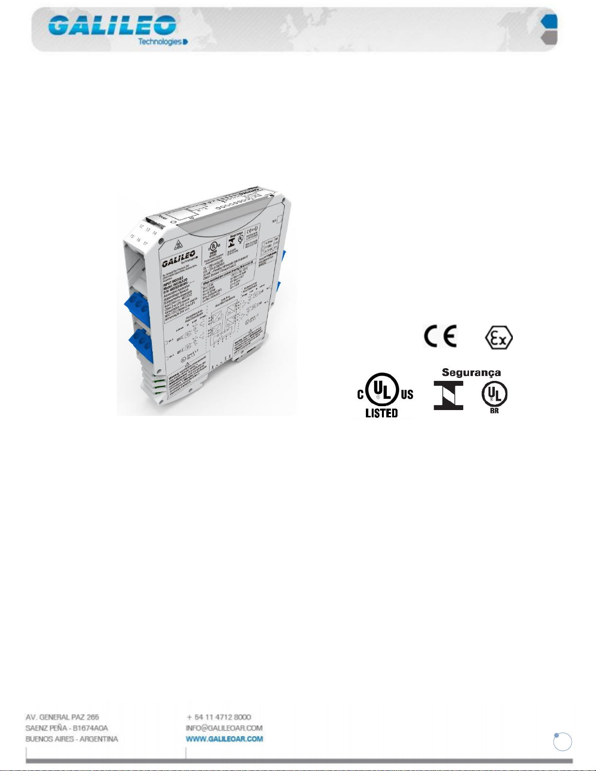
2. Product type
This manual summarizes the use of the following product:
Type MODC03B003 Input module intrinsically safe
Picture is only a reference
Warning!
Advertisement!
Read instruction's manual before operation.
Lisez des instructions avant l’opération

7
3. Intended Use
3.1.General
If the equipment is used in a manner not specified by the manufacturer, the
protection provided by the equipment may be impaired.
The product is intended to be installed in a suitable external enclosure.
The device is used in control and instrumentation technology for transfer of
signals such as 20mA and 10V standard signals.
The device has intrinsically safe circuits that are used for operating intrinsically
safe field devices in hazardous areas. Use the device only within the specified
ambient and operating conditions. The device is designed for mounting on a 35
mm DIN rail. The device is intended to be powered by 24V NEC class 2,
IEC/EN/UL 60950-1 LPS or IEC/EN/UL 601010-1 Limited Energy power source.
Indoor use only or outdoor use when installed in an external enclosure suitable
for outdoor use.
The device may be installed in the non-hazardous area.
3.2.Technical Specification
This Input Module intrinsically safe transfers Analog signals from
4-20mA, 0-10V, PT1000, DI. Convert to digital signal, store and send by protocol
Modbus RS485.
Each channel could be settable by a jumper to read any analog signal before
mentioned. The Input Module intrinsically safe prevents the transfer of
unacceptably high energy from the safe area into the hazardous area.
The zener diodes in the Zener Barrier are connected in the reverse direction. The
breakdown voltage of the diodes is not exceeded in normal operation. If this
voltage is exceeded, due to a fault in the safe area, the diodes start to conduct,
causing the fuse to blow. The Zener Barrier has a positive polarity.
3.3 Technical Data
Mechanical Specifications
Mounting
Snap-on 35 mm DIN mounting rail according to EN 60715
Housing Material
Polyamide (PA)
Dimensions
Dimension drawings refer to chapter Dimensions.
Degree of Protection
IP20 according to EN 60529
Connection
•Screw terminals for leads of up to a max. of 2 x 2.5 mm2 (2 x 14 AWG)
•Connection specifications refer to chapter Electrical wiring drawings.
• Observe the tightening torque of the terminal screws. The tightening
torque is 0.5 Nm to 0.6 Nm.
Ambient Temperature
-20 °C to +45 °C (-4 °F to +113 °F)
Storage Temperature
-25 °C to +70 °C (-13 °F to +158 °F)
Relative Humidity
max. 80 % without moisture condensation
8
4. Mounting
Do not mount the device in the dust hazardous area.
Maximum supply voltage 24Vdc.
Operation ambient temperature -20°C to +45°C.
Altitude up to 2,000 m.
Maximum relative humidity 80 % for temperatures up to 31 °C
decreasing linearly to 50 % relative humidity at 40 °C.
The device fulfills a degree of Protection IP20 according to EN 60529
The Zener Barrier is secured to a DIN rail using a tab and screw.
Additionally, a snap-in spring mounting system and can be removed with
an Allen to remove the screw and then a flat head screw driver by
inserting the screw driver head in steel tab on the DIN rail side and
pulling or prying to overcome the spring’s force.
Warning!
Advertisement!
The device must be use in PCB-vertical position!
L'appareil doit être utilisé en position verticale PCB!

9
5. Equipment installation and operation.
5.1Connections to the supply
Danger!
Danger to life from incorrect installation
Incorrect installation of cables and connection lines can compromise the
function and the electrical safety of the device.
• Observe the permissible core cross-section of the conductor.
• When using stranded conductors, crimp wire end ferrules on the
conductor ends.
• Use only one conductor per terminal.
• When installing the conductors, the insulation must reach up to the
terminal.
• Observe the tightening torque of the terminal screws.
• Supply voltage fluctuations up to ±10 % of the nominal voltage.
1. Ground the device. Use the DIN rail to ground connection of the
Zener barrier for grounding.
2. Connect the field circuit.
3. Connect the power supply & Modbus communication.
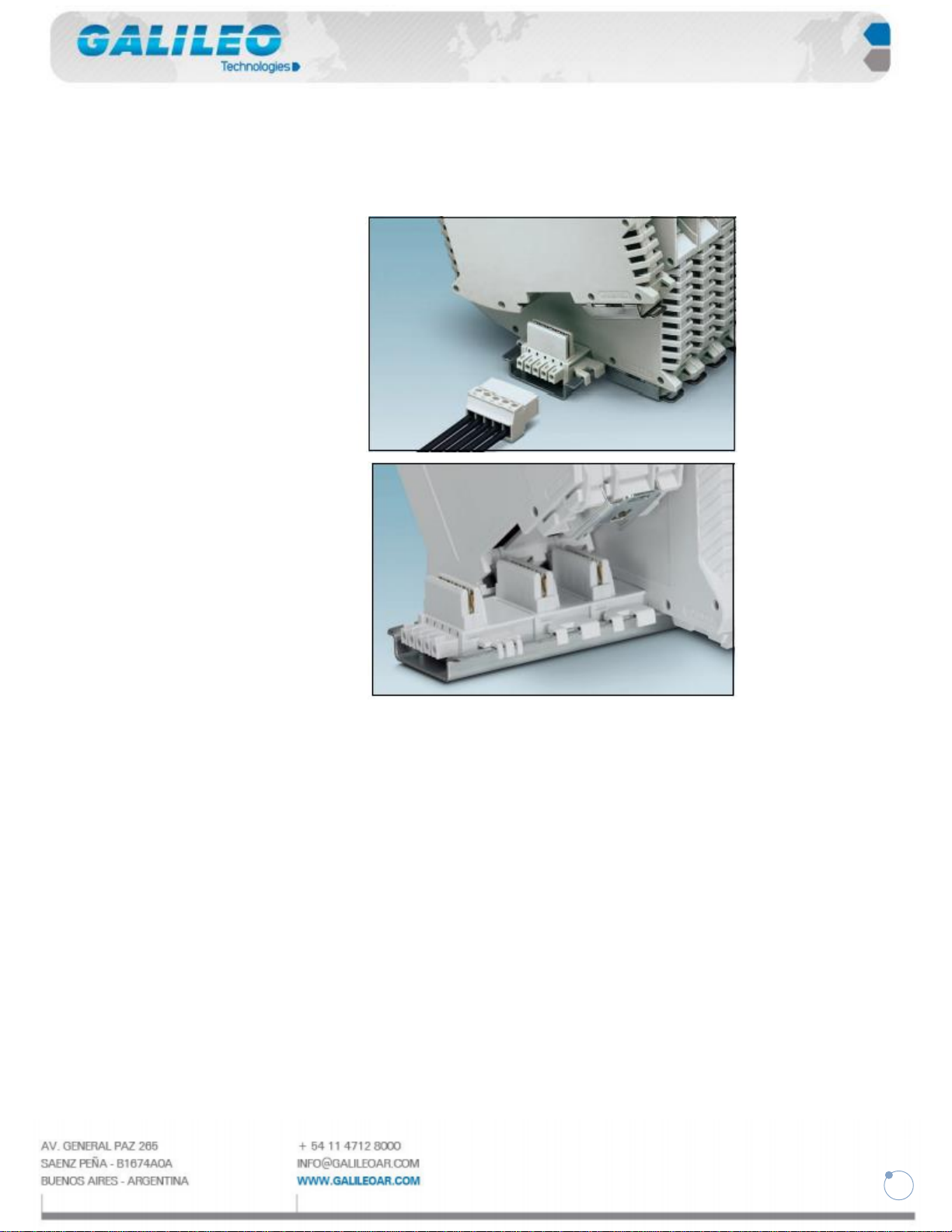
10
The DIN rail connector is integrated into the DIN rail. The bus connector
has 5 positions for energy supply and data transmission. It connects
several zener barrier modules, which are mounted on the DIN rail.
5.2 Equipment Operation
The barrier should be connected into the circuit while it is unpowered.
The voltage through the barrier under normal operation should not
exceed the rated Uo voltage. DC voltages and AC voltages of up to 1 MHz
pass through the barrier without attenuation. Any voltage above the
rated voltage is clamped to the rated voltage until the current exceeds
40 mA at which time an internal fuse is blown. Resistors are included in
the device to limit the available current in the Hazardous area. The
device protects the Hazardous area from high voltages and currents
which may cause sparks. The barrier must be connected using the proper
wires, wire gauge and codes as shown in the drawing on chapter
“Electrical wiring drawings” & “Electrical/Electromechanical drawings”.
Table of contents
Popular Control Unit manuals by other brands

Festo
Festo Compact Performance CP-FB6-E Brief description

Elo TouchSystems
Elo TouchSystems DMS-SA19P-EXTME Quick installation guide

JS Automation
JS Automation MPC3034A user manual

JAUDT
JAUDT SW GII 6406 Series Translation of the original operating instructions

Spektrum
Spektrum Air Module System manual

BOC Edwards
BOC Edwards Q Series instruction manual

KHADAS
KHADAS BT Magic quick start

Etherma
Etherma eNEXHO-IL Assembly and operating instructions

PMFoundations
PMFoundations Attenuverter Assembly guide

GEA
GEA VARIVENT Operating instruction

Walther Systemtechnik
Walther Systemtechnik VMS-05 Assembly instructions

Altronix
Altronix LINQ8PD Installation and programming manual


