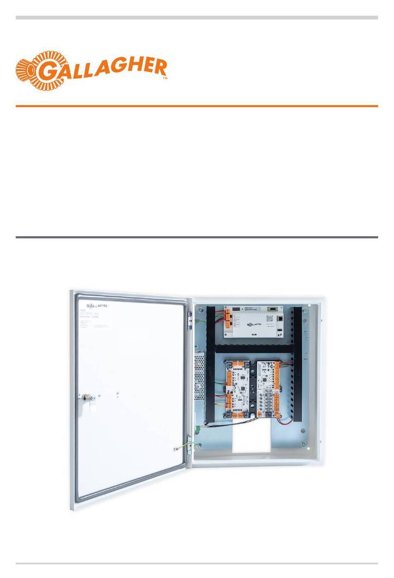
Gallagher C500306 Quick start guide

Gallagher
SMB USA Base Kit
Installation Note
Gallagher SMB USA Base Kit, T11 White Reader: C500306
Gallagher SMB USA Base Kit, T11 Black Reader: C500307
Gallagher SMB USA Base Kit, T15 White Reader: C500308
Gallagher SMB USA Base Kit, T15 Black Reader: C500309
Gallagher SMB USA Base Kit, T30 White Reader: C500311
Gallagher SMB USA Base Kit, T30 Black Reader: C500312
Edition 1.2 | December 2023

Introduction
Thank you for choosing Gallagher.
The Gallagher SMB security solution has been designed to meet the security needs for small
to medium businesses. It is a fully integrated cloud-based security system that offers intruder
alarm, access control, monitoring and user management all within one mobile app.
Kit contents
Check the cabinet contains the following items:
• 1 x Gallagher SMB Controller (C500100)
• 2 x Gallagher HBUS 8In 4Out Board (C300680)
• 1 x LSP 150 W PSU (C305747)
• 1 x LSP D8 Power Distribution Module (C305743)
• 1 x LSP B100 Secondary Voltage Module (C305740)
• 1 x Metal Mounting Plate with ducting
• 1 x Door earth wire
• 1 x Wiring loom and associated internal cable assembly
• 1 x Gallagher SMB T15 (C500481/480), T11 Reader (C500430/431) or T30 Keypad
Reader (C300490/491) located in a separate carton
Check the plastic bag contains the following items:
• 2 x Cabinet keys
• 32 x 4k7 ohm resistors
• 1 x White sticker (for rear optical tamper)
Note: The 7 Ah 12 V standby batteries and power lead are not provided.
Additional items are:
• SMB US Monitoring Kit (C500615) includes Alula BAT-Connect
• SMB US Expansion Kit (C500310)
• 1 x HBUS 16In 16Out Board (C300688)
• 1 x HBUS 8 Port Hub (C300698)
All hardware items with an associated part number can be ordered as replacement parts.

What's connected?
The hardware within the kit is pre-wired to support the site's default software configuration.
+
-
+
-
B
A
+
-
B
A
Controller
LAN
IN 16
IN 15
IN 14
IN 13
B
A
GND
VIN
IN 12
IN 11
IN 10
IN 9
OUT 5 OUT 6
OUT 7 OUT 8
Secondary
8In 4Out
Board
Reader
Battery Low
Mains Fail
IN 1
IN 2
IN 3
IN 4
B
A
GND
VIN
IN 5
IN 6
IN 7
IN 8
OUT 1 OUT 2
OUT 3 OUT 4
Primary
8In 4Out
Board
SYS AC
Battery
(not supplied)
Battery
(not supplied)
FAI
N EG L
Main Earth Connection
Mains coming into
the cabinet
24V 6A Life
Safety Power
Supply Unit
12V 4A B100
Power Supply
Converter
D8 Fused
Power
Distribution
Board
D1
D2
D3
D4
D5
D6
D7
D8
Earth connected
to cabinet wall
Alula D7 connection
Set JP7 to position 2
Earth connected
to cabinet door
JP1
JP2
JP9
Blk:BAT-
Red:BAT+
Blk:BR
Blu:DC1+
Blk:BR J2
Org:B2 J3
Blu: B1 J1
Blk:BR J3
Blu:DC in J1
Blk:BR J6
Org:DC out J5
Blu: DC in J4
FLEX IO

Installation
The installation of this kit must be carried out by a Gallagher SMB Partner.
Follow the instructions in this document to install the kit.
ATTENTION: This equipment contains components that can be damaged by electrostatic
discharge. Ensure both you and the equipment are earthed before beginning any servicing.
1. Install the cabinet
The cabinet is a secure metal enclosure containing the electrical equipment.
The cabinet also provides installation space for four 7 Ah 12 V batteries.
Before you begin
• Location
The cabinet is designed to be mounted on the wall and should be installed in a secure
room that is hidden from casual observers but allows frequent access. The room must
provide environmental and extreme temperature protection, AC mains power availability,
and security cable availability (for the low voltage connections). It is preferable for
optimal work height that the cables exit the wall and enter the cabinet at eye height or
just below, (i.e. approximately 1.6 m (5.25 ft) from the floor). The solution is considered a
permanently connected system and is not intended to be moved once installed.
• Dimensions
Cabinet - Height: 620 mm (24.4"). Width: 372 mm (14.65"). Depth: 150 mm (5.9").
Mounting holes - 379.5mm (14.94") bottom to middle key holes. 593mm (23.34") bottom
to top holes.
• Earthing
The cabinet has an earth wire connected to the cabinet door, cabinet body, power supply
unit and the main's supply earth wire. When the gear plate gets taken out of the cabinet
to hang the cabinet on the wall for the first time, it is necessary to disconnect the earth
wire from the door and from the cabinet body. They must both get reconnected (as well as
the mains earth connection) after refitting the gear plate in the cabinet to comply with the
local electrical regulations before turning on the mains supply.
• Tamper detection
The controller's front optical detector uses the reflective metal plate (pre-installed on the
inside of the cabinet door) to detect a change in light when the cabinet door is opened.
The controller's rear optical detector uses the light pipe in the back face of the cabinet,

and a rear tamper sticker on the wall to detect a change in light when the cabinet is
removed from the wall.
• Locking the cabinet
Two cabinet keys are provided to secure the contents of the cabinet.
• Knockouts
The knockouts in the side panels of the cabinet can be carefully tapped or cut out.
Procedure
1. Disconnect the earth wires connected to the cabinet door and left inside of cabinet and
remove the door for ease of installation.
2. Remove the backplate from the cabinet by unscrewing the two nuts (centre left-hand side
of the I/O board and D8 module) and lift it out.
3. Identify and create the knockouts needed for cables and the antenna (if using the Alula
BAT-Connect, refer to separate installation note).
4. Mark the position of the six mounting holes and rear tamper detector (light pipe) on the
cabinet mounting surface.
5. Fix the rear tamper sticker to the mounting surface. The sticker must align with the light
pipe located in the back face of the cabinet.
6. Secure the cabinet to the wall, using a minimum of four securing anchors. The cabinet
must be tight and flush against the wall. This ensures the distance between the rear
tamper sticker and the controller's rear tamper detector is kept to a minimum.
7. Hook the backplate under the bolt heads on the right-hand side and align the two holes
with bolts.
8. Secure the backplate back into place with two nuts.
9. Reconnect the earth wires to the door and to the body of the cabinet.
10.If using the Alula BAT-Connect for monitoring, refer to the US Monitoring Kit installation
details.
11.An Expansion Kit is availale to increase capacity to support more doors, refer to the US
Expansion Kit installation details.

2. Install readers
The default configuration provides allocation for one reader. It is recommended at least
one reader be configured to a site. This allows a user to arm or disarm locally using their
smartphone, in the event that the site losses internet connectivity. The smartphone uses
Bluetooth to communicate with the reader.
Doors can be configured without a reader, if required.
The HBUS communications protocol allows a single reader to communicate over a distance
of up to 500 m (1640 ft) from the controller, when using data only in a single CAT5E cable.
Cabling should be a minimum size of 0.2 mm2(24 AWG).
Connect the reader tail to the building cable. All cabling between HBUS devices should use
‘daisy chain’ wiring. This allows you to have multiple devices on the same cabling run. The end
devices on the HBUS run must be terminated. To terminate a reader, connect the orange wire
to the green wire.
Should you require multiple doors, the HBUS 8 Port Hub (C300698) can be utilized. This hub
supports the star wiring of eight HBUS devices to the hub's eight ports.
Note: you will still need to provide power to the door.
A
B
-
+
Controller
HBUS A
HBUS B
Negative
Positive
HBUS Termination
Not used
Not used
Green
Brown
Black
Red
Orange
White
Blue
Reader tail Building
cable
RS485
2
The reader is designed to be mounted on any solid flat surface. However, installation on metal
surfaces, particularly those with a large surface area will reduce read range. The extent to
which the range is reduced will depend upon the type of metal surface. Use a spacer plate or
the reader mount block (C300951) accessory to improve the read range.
The recommended mounting height for the reader is 1.1 m (3.6 ft) from the floor level to the
centre of the reader. However, this may vary in some countries, and you should check local
regulations for variations to this height. If using conduit, the reader can be mounted on a
mounting block (C300951).

Bezel
Building cable
No. 6 pan head screw
Building cable
Facia
Reader tail
Connection
Fit screw to secure facia to bezel
3. Connect inputs and outputs
Two 8In 4Out Boards are pre-installed in the cabinet. The Primary board is directly below the
controller.
The boards provide connection for a total of 16 inputs and 8 outputs. Two of the 16 inputs,
on the Primary board, are used for monitoring mains power failure and battery low.
The remaining 14 inputs can be used to connect sensors.
The HBUS 16In 16Out Board can be utilized with the SMB Kit to expand the solution.
Connect inputs and outputs, as required. Fit two 4K7 resistors as close as possible to the
device being monitored. When the monitored device incorporates a normally-closed tamper
switch, it can be wired in series with resistor R1. All devices connected to a single I/O board
must share the same resistor value. The resistance value for an I/O board can be changed
within the SMB Configuration App.

Relays are provided as ‘dry’ contacts or ‘electromagnetically switched’ contacts. Each relay is
rated 3 Amps at 24 Vdc for a resistive load, or 1 A at 24 Vdc for an inductive load.
The relay is controlled by the assigned output in the SMB Configuration App. To make use of
the relay, terminate the positive constant supply to the common termination of the relay and
nominate either Normally Open (N/O) or Normally Closed (N/C) termination to operate the
external device.
The D8 Fuse Board provides power distribution. The board can be used to power locks,
sensors, readers, and sirens, while maintaining circuit protection. Jumpers are used to draw
either 12 Vdc or 24 Vdc from the board. The default jumper position is one which draws
24 Vdc, designed to power locks at 24 Vdc. Change the jumper to position two, if you want to
draw 12 Vdc from the board.
Reference the LifeSafety Power D8 Installation Manual for further information.
The B100 provides an additional voltage in a conjunction with the LifeSafety FPO150. The
B100 voltage input is 24 Vdc from the FPO150 and the secondary voltage output is 12 Vdc
(DC OUT). 12 V required for the controller and I/O boards and 24 V is required for powering
locks. The jumpers should not be interfered with.
Reference the LifeSafety Power B100 Installation Manual for further information.
4. Connect power to the system
The cabinet comes pre-installed with a LifeSafety FPO150 which is used to power the
electrical hardware and charging up to four 7 Ah 12 V batteries (connected in a way to
support 24 Vdc backup. It provides a battery charging current of 2.5 A.
Calculating battery life
The cabinet supports up to four 7 Ah 12 V batteries. To know how long your batteries will
support your cabinet, calculate the following:
(combined battery capacity*) ÷ (total current draw in amps**) = (battery life in hours)
*To find the combined battery capacity, add the Ah values of all your batteries.
**To find the total current draw, add the current draw of the individual units in your cabinet.
Refer to the end of this installation note and separate hardware installation notes for current
draw values.

LifeSafety FPO150
The AC mains connection to the LifeSafety’s FPO150 power supply must be followed in
accordance with LifeSafety’s installation manuals. All AC mains electrical connections must
comply to the local electrical authority’s codes and NFPA section 70. Installation & service
should be performed by a qualified service personnel.
Refer to LifeSafety’s FPO150 Installation Manual for additional guidance.
The power supply provides two alarm outputs for monitoring battery low voltage and mains
failure alarms. Both the alarm outputs have on-board 4k7 EOL resistors fitted as standard.
Note: Do not apply voltage directly to the Battery Low or Mains Failure outputs, as this will
damage the monitoring circuitry, rendering the power supply unusable.
1. Using the battery leads provided, connect the required number of 7 Ah 12 V batteries to
the FPO150. To provide 24 Vdc battery backup, connect the batteries as shown.
Battery
(not supplied)
Positive
(+)
Negative
(-)
Battery
(not supplied)
Positive
(+)
Negative
(-)
Battery leadBattery lead Battery lead
2. The red wire connects to the red/positive battery terminal. The black wire connects to
the black/negative battery terminal. Use the orange wire provided as a jumper between
batteries.
Note: The batteries are not provided. The batteries are used as standby batteries, should
the mains power supply fail. Battery capacity requirements are to be calculated based
on the total load of the system and the number of hours required to run the system on
battery backup. For additional battery capacity, it must be housed in an additional cabinet
and connected to provide 24 Vdc back to the FPO150.
3. Terminate the AC mains earth to the main earth stud located on the right-hand side of
the gear plate. Earth termination must adhere to NFPA section 70 and local authority
electrical codes.

4. Connect the AC supply mains to the black (Live/Hot) and white (Neutral) wires in
accordance with LifeSafetys installation manuals, NFPA section 70 and local authority
electrical codes.
5. Energize the Lifesafety FPO150 mains.
Note: A power lead is not provided with the kit.
6. Ensure all equipment operates correctly, both with mains power ON/batteries ON, and
with mains power OFF/batteries ON.
Battery Low alarm
The Battery Low system alarm will be triggered when the battery charge falls below 10.8 V.
If no battery is connected the Battery Low alarm will not activate. This output is connected to
Input 7 on the default configuration of the Primary 8In 4Out Board.
Mains Failure alarm
The Mains Failure system alarm will be triggered when the mains voltage falls below
approximately 90 V or when the mains voltage rises above approximately 250 V. This output
is connected to Input 8 on the default configuration on the Primary 8In 4Out Board.
Note: Both Battery Low alarm and Mains Failure alarm are sent as a system notification to the
customer via the Gallagher SMB app. These events are also visible in the Event History of the
controller in the SMB Configuration app.

5. Connect the controller to the cloud
The controller connects to the site's local TCP/IP network.
1. Power on the controller.
2. Connect the site's Ethernet cable directly to the controller's Ethernet port.
3. Does the site's network use a proxy server to access the internet?
If no, continue to step 4.
If yes, you will need to supply the proxy server's hostname, port, and logon credentials
to the controller. Refer to the topic "7. Controller web browser configuration" later in this
document, to access the proxy settings.
4. Log into the SMB Configuration app and assign the controller to a site. If you have no login
details, please contact Gallagher Technical Support. Note: The SMB Configuration App is
a web-based portal and does not require you to download an app from the iOS or Google
Play Store.
Refer to the topic "6. Assign the controller to a site" later in this document.
5. Once assigned to a site, the controller will come online and connect to the cloud. An IP
address is automatically assigned to the controller via DHCP. There is no MAC address or
IP addressing required.
The controller will download the latest firmware and its default configuration from the
cloud. The download will take approximately 5 minutes. It may take longer if the download
occurs over cellular. The controller will restart after the download. Configuration changes
should not be published to the controller at this time. The Gallagher SMB solution only
supports the latest firmware version on the controller. The firmware version can be viewed
within the Properties section of the Controller lightbox in the SMB Configuration app.
If the controller doesn't come online, check the site has an internet connection. Plug your
laptop into the network and test the connection.
Ensure the following ports are open on the
site's network for the controller:
Port Protocol Details
67 UDP DHCP to internal router
53 UDP DNS to internal router
123 UDP NTP to time.google.com
443 TCP SMB Cloud HTTPS

6. Assign the controller to a site
1. Log into the SMB Configuration App.
Note: Login details can be requested from Gallagher Technical Support.
2. Has the site been created?
If no, continue to step 3.
If yes, go to step 6.
3. Select the +ADD NEW SITE located at the top of the screen.
The 'New Site' lightbox displays.
4. Enter a name for the site and complete all fields.
The key account holder will be the first person from your customer’s site to download the
Gallagher SMB App. The Key Account holder performs a similar role to a facility manager
and is the person who will invite other users to the site.
Select the Site uses tags checkbox if the site will be issuing key tags to users. Selecting
this checkbox will enable tag assigning functionality within the Gallagher SMB App.
Note: If using tags, cards, or user codes to arm & disarm an area, change the Locally
disarm area to Single Factor within the Area lightbox.
5. Select the Save button.
The site is created, and the default configuration is displayed.
6. Navigate to the site, click the Scan controller QR code button, scan the QR code printed
on the controller, then click the ASSIGN CONTROLLER button. If using a laptop, take a
photo of the QR code using your phone and present it to the laptop.
ASSIGN CONTROLLER
Scan controller QR code
Controller ID
Note: If you're unable to scan the controller's QR code, you can enter the controller's ID in
the Controller ID field, then click the ASSIGN CONTROLLER button. The controller's ID is
printed on the controller, below the QR code.
The controller will download the latest firmware and it's default configuration from the
cloud. If the message Cannot assign controller displays, it has already been assigned to a
site.

7. Controller web browser configuration
The Controller’s cloud configuration web pages allow configuration of specific Controller
settings, including the Controller’s date/time and NTP server if needed.
To connect to the Controller’s cloud configuration web pages, there are two methods:
Method Procedure
Navigate to the
Controller's IP
address
1. Find the IP address that has been assigned to the Controller by the local
DHCP server.
2. Set DIP switch 1 to ON.
3. Connect a laptop/PC to the same network as the Controller.
4. Using a web browser, go to the Controller’s cloud configuration web page,
replacing<ip_address> with the assigned IP address for the Controller:
http://<ip_address>/cloud/
The Sign In dialog displays.
5. Enter cloud for the username, then GGLcloud for the password and press
Enter.
The Gallagher Cloud Controller Configuration web page displays.
6. Select the required link to configure the Controller as needed.
7. When finished, set DIP switch 1 to OFF.
Reset the
Controller's IP
address, then
navigate to it
If you cannot find the Controller's DHCP IP address, the Controller can use
the default IP address bypowering it on with DIP switches 1, 2, and 3 ON.
The Controller then uses the following default addresses:
• Controller IP: 192.168.1.199
• Gateway: 192.168.1.198
• Subnet: 255.255.255.0
1. Connect the Controller to your PC via the Controller's Ethernet port.
2. Set DIP switches 1, 2 and 3 to ON.
3. Power cycle the Controller.
4. Using a web browser from a PC on the same subnet as the Controller,
enter the default IP address of the Controller as follows:
http://192.168.1.199/cloud/
The Sign In dialog displays.
5. Enter cloud for the username, then GGLcloud for the password and press
Enter.
The Gallagher Cloud Controller Configuration web page displays.
6. Select the required link to configure the Controller as needed.
7. When finished, set DIP switches 1, 2 and 3 to OFF.

8. Configure the site
Configure the site using the SMB Configuration App. Configure Areas, Inputs, Outputs,
Doors, then click PUBLISH to download the configuration changes to the controller.
For configuration instructions, refer to the Help Centre for Installers.
9. Test the site
Test Mode allows technicians to install, configure, and test an SMB site without alarming
others by setting off sirens or other devices activated in response to an alarm. Test mode
also prevents Site Managers, guards, and monitoring services from responding to alarms
generated while the system is being tested.
1. Click Enable Test Mode from the Site Actions
2. Test Mode can only be enabled for a period – set the time for Test Mode to expire
3. If Guarding or Monitoring is enabled, a warning will display advising the Technician to
inform the Monitoring station or Guarding company.
4. Test buttons will appear next to the Outputs. Alarm Relays are bypassed, Technicians can
‘chirp’ test outputs from this screen.
5. Click the Test button next to each Output
6. Once testing is complete click Disable Test Mode to disable it immediately, or it will
automatically disable at the set expiry time.
Note: Once a site is activated, Test mode can only be enteren when Installer Mode is enabled.
10. Initialise tampers
The front optical tamper detector will sense when the cabinet door has been opened. The rear
optical tamper detector will sense when the cabinet is removed from its mounting surface.
When you have finished wiring the devices and no longer need to access the cabinet:
1. Close and lock the cabinet door using the key provided.
2. Within the SMB Configuration App, click the controller at the top of the hardware tree.
3. Within the site's controller lightbox, select Restart.

11. Activate the site
When the site is activated, it will become operational and billing will commence. A site can be
activated as soon as the system is operational, allowing the Key Account Holder to start using
the system before you have fully completed the installation.
Select Activate Site. This will send an 'Account Activation' email to the Key Account Holder.
The Key Account Holder will need to follow the instructions in the email to download the
Gallagher SMB App and accept their credentials.
Note: If you are unable to onboard the Key Account Holder, ensure they have a PIN or pattern
set on their phone.
The site has now been handed over to the customer. The SMB Configuration App changes to
‘read-only’ for the site. If you need to make additional configuration changes, the customer
must enable Installer Mode within the Settings of the SMB App.
Controller Run LED flash patterns
Flash Pattern Meaning
Short flash Long
flash (1 s cycle)
100 ms on, 250 ms off
400 ms on, 250 ms off
Boot code monitor running, network
unplugged
Half flash 450 ms on, 50 ms off (2Hz flash) Controller resetting
Fast 130 ms on, 130 ms off (4Hz flash) Initialising
1 flash 500 ms on, 500 ms off (1Hz flash) Normal running
2 flashes 2 flashes - pause (each flash is 50 ms
on, 400 ms off, 1.2 s pause)
Controller is operating, connected to
the cloud but has no configuration
3 flashes 3 flashes - pause (each flash is 50 ms
on, 400 ms off, 1.2 s pause)
Controller has a valid set of keys but
has not connected to the cloud
4 flashes 4 flashes - pause (each flash is 50 ms
on, 400 ms off, 1.2 s pause)
No private keys or certificate loaded,
so will be unable to authenticate with
the cloud. Contact Gallagher Technical
Support.
5 flashes 5 flashes - pause (each flash is 50 ms
on, 400 ms off, 1.2 s pause)
Controller has a connection to the
cloud but either the cloud has failed
to authenticate the controller, or the
controller has failed to authenticate
the cloud. Contact Gallagher Technical
Support.
6 flashes 6 flashes - pause (each flash is 50 ms
on, 400 ms off, 1.2 s pause)
Controller does not have runnable
firmware. Contact Gallagher Technical
Support.

Disclaimer: Please note that information contained in this document is intended for general information only. While every effort has been taken to ensure accuracy at the date
of the document, there may be errors or inaccuracies and specific details may be subject to change without notice. Copyright © Gallagher Group Ltd.
Technical specifications
Controller Value
Voltage 9 Vdc - 16 Vdc (must be at least 3 V above output voltage)
Current without devices connected 110 mA
Maximum current per RS485 port 750 mA
Temperature range -10 °C to 70 °C (14 °F to 158 °F)
Humidity 0 - 95% non-condensing
10/100BaseT Ethernet port 1 x 10 Mbs/100 Mbs
I/O Boards Value
8In 4Out Board operating current 45 mA DC (relays OFF)
200 mA DC (relays ON)
8In 4 Out Board power rating 0.61 W (relays OFF)
2.72 W (relays ON)
Fuse Onboard 1 A resettable polyfuse
Reader Value
Voltage 9 Vdc - 16 Vdc
Current Idle1Maximum2
T11 at 9 Vdc 106 mA 176 mA
T11 at 13.6 Vdc 80 mA 142 mA
T15 at 9 Vdc 110 mA 168 mA
T15 at 13.6 Vdc 81 mA 136 mA
T30 at 9 Vdc 130 mA 241 mA
T30 at 13.6 Vdc 87 mA 160 mA
Temperature range -35 °C to +70 °C (-31 °F to 158 °F)
Direct sunlight may increase the internal reader
temperature above the ambient temperature level
Humidity 0 - 95% non-condensing
Environmental protection IP683
Impact rating IK073
Unit dimensions T11 Reader:
Height 115 mm (4.5 inches)
Width 70 mm (2.8 inches)
Depth 12 mm (0.5 inches)
T15 Reader:
Height 139 mm (5.47 inches)
Width 44 mm (1.73 inches)
Depth 23 mm (0.9 inches)

T30 Keypad Reader:
Height 118.0mm (4.65 in)
Width 86.0 mm (3.39 in)
Depth 26.7 mm (1.05 in)
Maximum number of access
controlled doors on one SMB controller
10
Standards and compliance FCC, RCM, RoHS
1 The reader is idle
2 Maximum reader current during credential read
3 Environmental protection and impact ratings are independently verified
LifeSafety Power FP0150
https://www.lifesafetypower.com/docs/im_fpo.pdf
D8 Simple Distribution Board
Input Voltage 5 - 24 Vdc nominal
Current 12 A maximum
Standby Current 65 mA
Output Voltage Same as input
Current (D8) 3 A Resistive
Current (D8P) 2.5 A Resistive (Class 2 Power Limited)
Fuse (D8 Only) 3 A ATM automotive style
Size D8/D8P 4.00" x 2.50" x 1.0"
(102mm x 64mm x 26mm)
Weight D8/D8P 0.15lb (0.07kg)
B100 DC-DC Convertor
Input Voltage 8 - 25 V (must be at least 3 V above output
voltage setting)
Current 3.5 A maximum
Standby Current 35 mA
Output Voltage 4.7 - 23 V
Current 4 A maximum (Class 2 Power Limited)
Fuse (D8 Only) 7.5 A ATM automotive style
Size 4.00" x 2.50" x 1.75"
(102mm x 64mm x 45mm)
Weight 0.20lb (0.09kg)
SMB USA Base Kit standards and compliance
FCC, RCM, RoHS
This manual suits for next models
5
Table of contents
Other Gallagher Control Unit manuals
Popular Control Unit manuals by other brands

Rockwell Automation
Rockwell Automation Allen-Bradley 1441-DYN25-MBAL user manual

EFI
EFI EB-32 Installation and service guide

Tekmar
Tekmar tekmarNet 4 Setpoint Control 161 Data brochure

Emerson
Emerson SAPAG CLASAR Series Technical description, installation, operating and maintenance instructions

Campbell
Campbell CDM-A100 Series instruction manual

RFCOM TECHNOLOGIES
RFCOM TECHNOLOGIES RTBTM01 user manual