Gamber Johnson 7160-0564 User manual

Product Mounting Disclaimer
Gamber-Johnson is not liable under any theory of contract or tort law for any loss, damage, personal injury, special, incidental or consequential damages for personal injury or other damage
of any nature arising directly or indirectly as a result of the improper installation or use of its products in vehicle or any other application. In order to safely install and use Gamber-Johnson
products full consideration of vehicle occupants, vehicle systems (i.e., the location of fuel lines, brakes lines, electrical, drive train or other systems), air-bags and other safety equipment is
required. Gamber-Johnson specifically disclaims any responsibility for the improper use or installation of its products not consistent with the original vehicle manufactures specifications
and recommendations, Gamber-Johnson product instruction sheets, or workmanship standards as endorsed through the Gamber-Johnson Certified Installer Program.
INST-647
Product Mounting Disclaimer
Gamber-Johnson is not liable under any theory of contract or tort law for any loss, damage, personal injury, special, incidental or consequential damages for personal injury or other damage
of any nature arising directly or indirectly as a result of the improper installation or use of its products in vehicle or any other application. In order to safely install and use Gamber-Johnson
products full consideration of vehicle occupants, vehicle systems (i.e., the location of fuel lines, brakes lines, electrical, drive train or other systems), air-bags and other safety equipment is
required. Gamber-Johnson specifically disclaims any responsibility for the improper use or installation of its products not consistent with the original vehicle manufactures specifications
and recommendations, Gamber-Johnson product instruction sheets, or workmanship standards as endorsed through the Gamber-Johnson Certified Installer Program.
INSTALLATION INSTRUCTIONS
Product
Revision
Form
If you need assistance or have questions, call Gamber-Johnson at 1-800-456-6868
Printing Spec:
PS-004
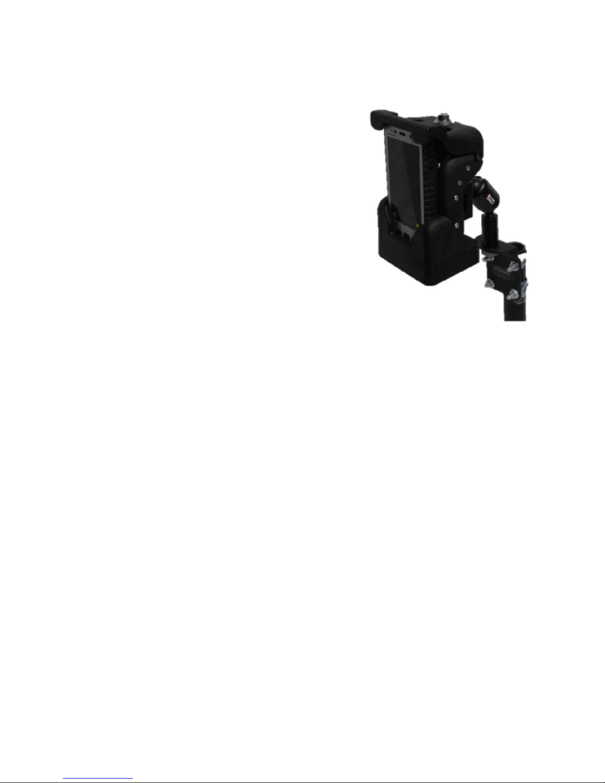
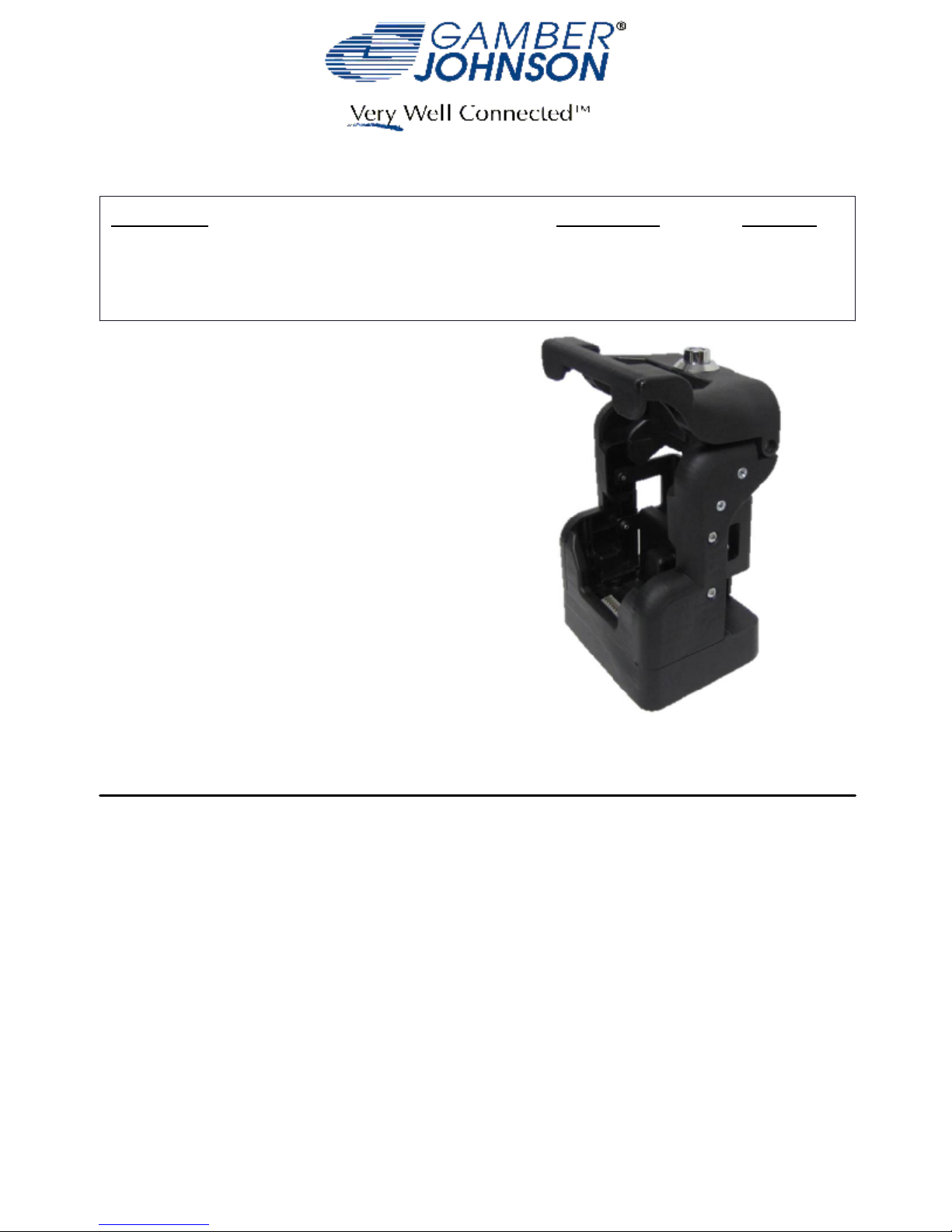
PANASONIC FZ-X1 / FZ-E1 POWER CRADLE
7160-0564
This instruction sheet is for the following products:
Panasonic FZ-X1 / FZ-E1 Power Cradle
Item No. 7160-0564 (-P) (-E)
CRADLE-PANASONIC-FZX1/E1
Item No. 7160-0594
* These instructions are for the Cradle and
Power Cradle
only. For instructions on
features, set-up and operation of the FZ-X1 / FZ-E1 computer, please refer to the manuals
provided by Panasonic with the computer.
** This Cradle and
Power Cradle
is designed to be used with a variety of Gamber Johnson
mounting systems. Installation for other Gamber Johnson products are provided with each
individual product.
Pg 1
Figure: 1
Rev. C
© Copyright 2016 Gamber-Johnson, LLC
7160-0594
CRADLE-PANASONIC-FZX1/E1

IMPORTANT SAFETY INFORMATION FOR
INSTALLERS
Safety is dependent on the proper installation and servicing of this Power Cradle. It is important to read
and follow all instructions before installing this product.
To properly install Gamber Johnson's Power Cradle you must have a good understanding of
automotive electrical procedures and systems, along with proficiency in the installation and service of
aftermarket vehicle equipment.
There are no adjustments required at any time of the electrical components within the charging station.
Opening the electronic housing will void the product warranty.
During Installation:
DO NOT connect this Power Cradle to the vehicle battery until:
•
ALL other electrical connections are made
1.
Mounting of ALL components is complete
2.
VERIFICATION that no shorts exist in the entire system
3.
DO NOT install equipment or route wiring or cords in the deployment path of any airbag.
•
When drilling into the vehicle. DO make sure that both sides of the surface are clear of anything
•
that could be damaged.
CAUTION: If wiring is shorted to the frame, high current conductors can cause hazardous
sparks resulting in electrical fires or flying molten metal.
After Installation:
Test the Power Cradle to ensure that it is working properly.
•
File these instructions in a safe place and refer to them when performing maintenance or re-
•
installing.
WARNING: Failure to follow all safety precautions and instructions may result in property
damage, serious injury or death.
PRE-INSTALLATION RECOMMENDATIONS
Conduct a "Bench Test"
Gamber Johnson strongly advises a "Bench Test" be conducted to verify that all electronic and software
issues are resolved prior to installation:
Make sure computer is operational by itself.
1.
Insert computer into the Power Cradle (make sure that the computer is powered down).
2.
Connect power to the Power Cradle if not already connected and turn on FZ-X1 (-E1) and verify
3.
computer is being charged.
*Gamber Johnson recommends positioning of all mounts and equipment in the vehicle prior to the actual
install to verify that mounting locations are safe and practical.
Pg 2

MOUNTING THE CRADLE AND POWER CRADLE
This Cradle and Power Cradle is designed to be used with a variety of Gamber Johnson mounting
systems. Installation instructions for Gamber Johnson products are provided with each individual product.
This Cradle and Power Cradle supports the AMPS and NEC hole patterns. Shown in this instruction
sheet connecting using Max3 swivel (sold separatly) which will allow end user to set up for multiple
positions when used with a pole.
Note: All mounting solutions come with the needed hardware.
Pg 3
Step 1:
Locate mounting bracket attached to backside of the
Cradle and Power Cradle. See Figure: 2.
Figure: 2
Step: 2
Remove 2 lower screws on the each side of the Cradle
and Power Cradle (4 total) that holds the mounting plate
in place. See Figure: 3.
Figure: 3
Step: 3
Remove mounting plate from Cradle and Power Cradle.
See Figure: 4
Figure: 4
Step: 4
Attach Max3 to the plate and tighten securely.
See Figure: 5.
Figure: 5
Bracket
screw
screw

Step: 5
Re-attach mounting bracket to the Cradle and
Power Cradle using the same screws removed
in Step: 2. Torque to 7 in-lbs. See Figure: 6
Step: 6
Screw together the Max3 into its mating part
that is attached to the pole. See Figure: 7
Step: 7
Unlock and press the button and swing open the
top latch of the Cradle and Power Cradle to allow
for the insertion of the FZ-X1 (-E1) computer as shown
in Figure: 8.
Step: 8
Close the top latch over the FZ-X1 (-E1) computer
and use the handle of the Max3 to postion the unit so
that it is best stituated for the user to use. See Figure: 9
Figure: 6
Figure: 7
Figure: 8
Figure: 9
Use handle
to adjust for
position
Pg 4

Figure:11
Figure: 10
Step: 10
Swing the cable assembly towards the back
and upward. See Figure: 11
Step: 9
Identify the location of the power jack. It is
located on the left hand side of the dock at the
base of the unit as you are facing the front of
the setup. Insert power plug into the jack.
See Figure: 10
Figure: 12
Step: 11
Bend cable around to that it can be attached to
the dock using a wire tie. Once secured to the
dock excess wire material can be cut off for
cleaner look. See Figure: 12
Panasonic recommends using a Lind Auto Adapter (Lind part No. PA1555-968) to power the
docking station. It can be ordered from Gamber Johnson (part No. 11798) or directly from Lind
Electronics, Minneapolis, Minnesota (952-927-6303).
Wire Tie
Pg 5
STEPS 9-11 REFER TO POWER CRADLE ONLY

INSERTING THE COMPUTER
Pg 6
When inserting the FZ-X1 (-E1) computer
1.
it is recommend to shut down the computer
completely.
Open Cradles and Power Cradle's top latch by
2.
depressing the lock button and lifting top latch
from the front and rotating it backwards.
When inserting the FZ-X1 (-E1) computer in,
3.
there are two guide rails located on the inside of
the Cradles and Power Cradle used for aligning
the computer for proper docking. Push down on
the FZ-X1 (-E1) computer until it is fully seated
in the dock.
Rotate the top latch back down until you feel the
4.
lock latch.
Boot the computer. If the computer shows that it
5.
is being charged, then the computer is ready for
use.
REMOVING COMPUTER FROM POWER CRADLE
Shut down the computer.
1.
Open Cradles and Power Cradle's top latch by
2.
depressing the lock button and lifting top latch
from the front and rotating it backwards.
Lift the FZ-X1 (-E1) computer to slide it out of
3.
the dock.
It is recommended to then close the top latch to
4.
stablize the latch.

This device complies with Part 15 of the FCC Rules. Operation is subject to
the following two conditions. (1) this device may not cause harmful
interference, and (2) this device must accept any interference received,
including interfernece that may cause undesired operation.
Certifications:
EN 55022:2010 CISPR 22:2008 Class B
•
EN 50498:2010
•
EN 50581:2012
•
Descriptions: Dock-Panasonic-FZ-X1 or FZ-E1 and Cradle-
Panasonic-FZX1/E1
GJ Model #'s: 7160-0564, 7160-0564-P, 7160-0564-E and 7160-0594.
Regulatory Model #: 7160-0564 & 7160-0594
Regulatory Certification Information
Gamber-Johnson LLC, 3001 Borham Ave.,
Stevens Point, WI, 54481, USA, 715-344-3482
Pg 7
This manual suits for next models
1
Table of contents