GAME AQUAQUIK 4510 User manual

UNIVERSAL PooL FILtER SyStEm
owNER’S mANUAL
MODELS 4510 AND 4511
Sand not included. USE ONLY No. 20 Silica Sand with a particle size of 0.45 mm – 0.55 mm
ImPoRtANt
Do Not REtURN PRoDUct to StoRE
For technical assistance and missing parts, call Customer Service toll-free
1.888.382.5988
(press 135 at any time)
Monday through Friday, 8 am to 5:00pm MST
Saturday, 8:00am to 1:00pm MST
ImPoRtANt
SAFEty RULES
Read all instructions BEFORE
assembling and using
this product.
KEEP THIS MANUAL.
MODEL 4510
MODEL 4511

2SAVE THESE INSTRUCTIONS

SAVE THESE INSTRUCTIONS3
Your AquaQuik™ Universal Pool Filter System has been
engineered and manufactured to our highest standard for dependability,
ease of operation and safety. With proper care, it will give you years of durable,
trouble-free performance. Thank you for your purchase.
PRIoR to ASSEmbLINg AND USINg thIS PRoDUct,
cAREFULLy READ AND ADhERE to ALL cAUtIoN AND ImPoRtANt
NotIcES LocAtED thRoUghoUt thIS mANUAL. FAILURE to comPLy
wIth thESE INStRUctIoNS mAy DAmAgE to thE PRoDUct oR cAUSE
SERIoUS PERSoNAL INjURy oR DEAth.
In this manual, some of the following callouts may be used. Please pay special attention to
these. CAUTION, IMPORTANT and STOP have the following meanings:
cAUtIoN
Used when injury or accidents may occur if the operating instructions, work instructions, work
procedures, etc. are either NOT strictly adhered to or not carried out all.
ImPoRtANt
Used when damage to the device may occur if the operating instructions, work instructions,
work procedures, etc. are either NOT strictly adhered to or not carried out all.
StoP
Calls attention to special details or information.
ImPoRtANt
Do Not REtURN PRoDUct to StoRE
For technical assistance and missing parts, call Customer Service toll-free
1.888.382.5988
(press 135 at any time)
Monday through Friday, 8 am to 5:00pm MST
Saturday, 8:00am to 1:00pm MST

4SAVE THESE INSTRUCTIONS
tAbLE oF coNtENtS
1. Safety Warnings . . . . . . . . . . . . . . . . . . . . . . . . . . . . . . . . . . . . . 5
2. General Information . . . . . . . . . . . . . . . . . . . . . . . . . . . . . . . . . . 6
How Sand Filtration Works . . . . . . . . . . . . . . . . . . . . . . . . . . . . . . . . . 6
Powering the Filter Pump. . . . . . . . . . . . . . . . . . . . . . . . . . . . . . . . . . . 6
Sand & Initial Preparation . . . . . . . . . . . . . . . . . . . . . . . . . . . . . . . . . . 7
Installation . . . . . . . . . . . . . . . . . . . . . . . . . . . . . . . . . . . . . . . . . . . 7
3. Technical Specifications . . . . . . . . . . . . . . . . . . . . . . . . . . . . . . . . 7
4. Parts List/Reference . . . . . . . . . . . . . . . . . . . . . . . . . . . . . . . . . . 8
5. Getting Started . . . . . . . . . . . . . . . . . . . . . . . . . . . . . . . . . . . . 10
Unpacking Your Filter System . . . . . . . . . . . . . . . . . . . . . . . . . . . . . . 10
Tools & Equipment Required . . . . . . . . . . . . . . . . . . . . . . . . . . . . . . . 10
Know Your Pool . . . . . . . . . . . . . . . . . . . . . . . . . . . . . . . . . . . . . . . 10
Filter Location . . . . . . . . . . . . . . . . . . . . . . . . . . . . . . . . . . . . . . . . 10
Power Source Requirements . . . . . . . . . . . . . . . . . . . . . . . . . . . . . . . 11
6. Assembly Instructions . . . . . . . . . . . . . . . . . . . . . . . . . . . . . . . . 11
Water Pump Assembly . . . . . . . . . . . . . . . . . . . . . . . . . . . . . . . . . . . 11
Filter Tank Assembly . . . . . . . . . . . . . . . . . . . . . . . . . . . . . . . . . . . . 12
7. Connecting the Filter System. . . . . . . . . . . . . . . . . . . . . . . . . . . . 15
For pools with 1¼” or 1½” Diameter Unthreaded Hoses . . . . . . . . . . . . . . 15
For pools with 2¼” Diameter Threaded Hose Connectors . . . . . . . . . . . . . 16
8. Valve Operations . . . . . . . . . . . . . . . . . . . . . . . . . . . . . . . . . . . 18
Filter Valve Settings & Functions . . . . . . . . . . . . . . . . . . . . . . . . . . . . . 18
Changing Valve Positions . . . . . . . . . . . . . . . . . . . . . . . . . . . . . . . . . 19
9. Filter Operations. . . . . . . . . . . . . . . . . . . . . . . . . . . . . . . . . . . . 20
Start Up . . . . . . . . . . . . . . . . . . . . . . . . . . . . . . . . . . . . . . . . . . . . 20
Cleaning Sand . . . . . . . . . . . . . . . . . . . . . . . . . . . . . . . . . . . . . . . . 20
Backwash Process . . . . . . . . . . . . . . . . . . . . . . . . . . . . . . . . . . . . . . 21
Backwash Do’s & Don’t’s . . . . . . . . . . . . . . . . . . . . . . . . . . . . . . . . . . 21
10. Maintenance . . . . . . . . . . . . . . . . . . . . . . . . . . . . . . . . . . . . . . 21
Adding Sand . . . . . . . . . . . . . . . . . . . . . . . . . . . . . . . . . . . . . . . . . 21
Cleaning the Hair and Lint Filter . . . . . . . . . . . . . . . . . . . . . . . . . . . . . 22
Winterizing the System . . . . . . . . . . . . . . . . . . . . . . . . . . . . . . . . . . 22
Safety Notes . . . . . . . . . . . . . . . . . . . . . . . . . . . . . . . . . . . . . . . . . 22
11. Troubleshooting. . . . . . . . . . . . . . . . . . . . . . . . . . . . . . . . . . . . 23
12. Limited Warranty Statement . . . . . . . . . . . . . . . . . . . . . . . . . . . . 24
13. Appendix . . . . . . . . . . . . . . . . . . . . . . . . . . . . . . . . . . . . . . . . 26
Model 4510 Exploded View Parts List Diagram. . . . . . . . . . . . . . . . . . . . 26
Model 4511 Exploded View Parts List Diagram. . . . . . . . . . . . . . . . . . . . 27

SAVE THESE INSTRUCTIONS5
1. SAFEty wARNINgS
READ ALL wARNINgS bELow. FAILURE to Do So coULD RESULt
IN SERIoUS PERSoNAL INjURy oR DEAth.
RISK OF SUCTION ENTRAPMENT HAZARD, WHICH, IF NOT AVOIDED CAN•
RESULT IN SERIOUS INJURY OR DEATH.
Do not block pump suction at the pump or in the pool as this can cause•
severe injury or death.
Electrical wiring MUST be installed by a trained professional and adhere•
to local code and regulations.
Avoid electric shock. DO NOT USE power extension cords.•
Connect ONLY to a Ground-Fault Circuit Interrupter (GFCI) power outlet.•
Consult a qualified, professional electrician for safe and proper installation
of the required electrical outlet.
Incorrectly installed equipment may fail, causing severe injuries or damage•
to the pump-filter system.
Never place or submerge the filter and/or pump in water.•
Trapped air in the pump-filter system may cause the tank cover to be blown•
off which can result in death, serious injury, or damage to the pump-filter
system. Ensure all air is out of system before operating.
NEVER change the position of the Multi-Port Valve while the system is•
operating. ALWAYS unplug the system first.
Install this product at least 10 feet away from the pool to prevent children•
from using the system to access the pool.
Never PLUG or UNPLUG this unit from an electrical source while standing•
in water or with wet hands (or while wet??).
NEVER service this unit with the electrical power cord connected.•
Do not use any petroleum based lubricant. Petroleum based products will•
destroy plastic parts.
Do NOT operate the system while the pool is in use.•
KEEP CHILDREN AWAY from all electrical equipment.•
NEVER ALLOW CHILDREN TO OPERATE THIS EQUIPMENT.•
thESE SAFEty wARNINgS ARE Not INtENDED to INcoRPoRAtE
ALL PoSSIbLE INStANcES FoR RISK AND/oR SEVERE INjURy.

6SAVE THESE INSTRUCTIONS
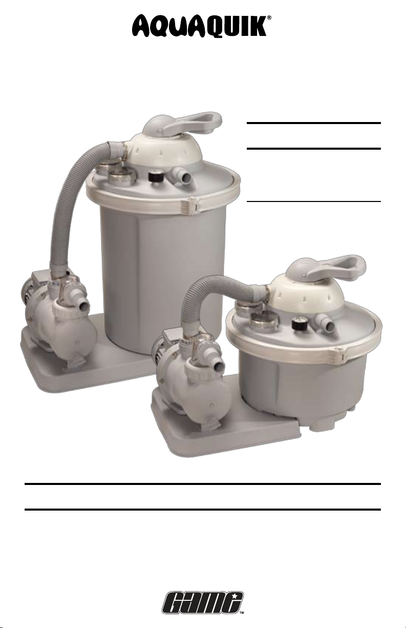
2. gENERAL INFoRmAtIoN
This manual provides information relating to the installation, utilization and
maintenance of the Universal Pool Filter System. The pump included with the
filtration system is a horizontal, self-priming centrifugal pump. For the pump to
function correctly, the water temperature must not exceed 95°F/35°C. The filter
included in the filtration system is equipped with a container drainage system,
pressure gauge and built-in container components. The filter container comes
ready to plug-in and is supplied with a user-friendly 7 Position Multi-Port Valve
integrated into the tank cover, an approved filter pump with hair and lint basket,
and a plastic base for ready on-site mounting.
How Sand Filtration Works
The Universal Pool Filter System is designed to use special silica sand to remove
dirt particles from pool water. Filter sand is loaded into the filter tank and functions
as a permanent dirt and debris removing media. Pool water, which contains dirt
particles, is pumped through the intake hose leading from the pool to the filter
tank and is directed by the filter control valve to the top of the filter tank. As water
is pumped through the filter sand, dirt particles are trapped by the bed of sand
and filtered out. The cleaned/filtered water is then returned from the bottom of the
filter tank, through the control valve and back to the pool through the return hose.
This sequence is continuous and automatic and provides total recirculation of pool
water through your filter and hose connections.
After a period of time, the accumulated dirt in the filter causes a resistance to
the flow of water and an increase in pump pressure (psi). When this happens, it is
time to clean (backwash) the filter. To backwash the system, you must change
the valve to the backwash position. When in backwash mode, the water flow is
automatically reversed through the filter so that it is direct to the bottom of the
tank, up through the sand, which flushes any trapped dirt and debris out through
the waste line. Once the filter is backwashed and cleaned of dirt, the control valve
should be moved into the rinse position to allow the sand to settle. After rinsing,
the filter valve should be changed back to the filtration position to resume
normal filtering.
Powering The Filter Pump
It should be noted that the Universal Pool filter System does not have an on/off
switch. Rather, power to the filter pump is connected and disconnected by means
of plugging in and unplugging the power cord from the power source. It is
important that you read and follow the instructions on proper power supply
sources (see Power Source Requirements, page 11) to avoid overloading the pump
motor and/or electric shock.

SAVE THESE INSTRUCTIONS7
Sand & Initial Preparation
The Universal Pool Filter System requires a specific type of sand (not included)
for optimum operation: namely, Number 20 Silica Sand with a particle size of
0.45 mm - 0.55 mm. You can purchase this sand at most pool supply stores.
While the sand will come packaged, it is important that the sand be cleaned
prior to running the filter system in filtration mode (see Filter Operations, page 20).
Installation
Read and understand this manual carefully before installation. Failure to follow all
instructions may result in electric shock, serious personal injury or death.
3. tEchNIcAL SPEcIFIcAtIoNS
Model 4510 (1/2 Horsepower Model)
Item U.S. Units Metric Units
Flow Rate 1950 GPH @ 6 PSI 7.4 m3/hr @ 0.4 Bar
MAX Operating Pressure 22 psi 1.5 Bar
Filtration Area 1.4 ft20.13 m2
Rated Voltage 110 VAC 110 VAC
Sand Volume 38 lbs 17 kg
Model 4511 (3/4 Horsepower Model)
Item U.S. Units Metric Units
Flow Rate 2330 GPH @ 6 PSI 8.8 m3/hr @ 0.4 Bar
MAX Operating Pressure 22 psi 1.5 Bar
Filtration Area 1.4 ft20.13 m2
Rated Voltage 110 VAC 110 VAC
Sand Volume 76 lbs 34 kg

8SAVE THESE INSTRUCTIONS
4. PARtS LISt/REFERENcE
Before starting installation, check to make sure all parts are present in package.
Primary Components
BASE PLATE (1) WATER PUMP (1)
FILTER TANK (1) TANK COVER / VALVE ASSEMBLY (1)
TANK COVER LOCK RING ASSEMBLY (1) FILTER-PUMP HOSE
(Model 4510 has threaded end)
TANK SEPARATOR PLATE (1) UPPER DISTRIBUTOR (1)
OWNER’S MANUAL
NOTE: Parts not shown to scale

SAVE THESE INSTRUCTIONS9
Parts Bag A
1 ¼”-1 ½” HOSE CONNECTOR (2) FLAT GASKET “A” (1)
O-RINGS (2) A: 2 ¼ “ Dia, B: 3” Dia HAIR & LINT STRAINER COVER (1)
Parts Bag B
SHORT INTEX® CONNECTOR (1) LONG INTEX® CONNECTOR (1)
PUMP MOUNTING HARDWARE O-RING (1) C: 1¼” Dia
HOSE CLAMP (2) FLAT GASKET “B” (2)
NOTE: Parts not shown to scale

10SAVE THESE INSTRUCTIONS
5. gEttINg StARtED
Unpacking Your Filter System
This product requires assembly.
Carefully remove the product and all parts. Make sure all items listed in the Parts
List/Reference are included. Please note that some parts may be pre-assembled.
Inspect everything carefully to make sure nothing is damaged.
Do not discard packing material until you have satisfactorily operated the product.
If any parts are missing or damaged, please call the number listed on the front page
of this manual.
NOTE: Some parts may be located within the filter tank. To access these parts you
must remove the tank cover.
Refer to Appendix A for a complete EXPLODED VIEW PARTS DIAGRAM
Tools & Equipment Required
The following items are not included with your new filter system, but will be
required for proper installation and operation:
#2 Phillips Screwdriver•
Rubber Mallet•
No. 20 Silica Sand (Model 4510 requires 38 lbs of sand; Model 4511•
requires 76 lbs of sand.)
A small container of silicone based lubricant•
G.F.C.I. (Ground Fault Circuit Interrupter) – Must be installed by•
a certified electrician
One 1½ inch backwash hose•
The above equipment list is based on the assumption that your above-ground pool
is assembled, filled with water, and that your pool is equipped with the necessary
filtration hoses needed to operate with a filter (cartridge or otherwise). If your pool
is not assembled, please refer to the pool’s installation manual for details. If you
do not have hoses for your pool’s intake and return, you will need to purchase the
hoses from a pool supply store.
This Universal Pool Filter System is designed to connect to pools with standard
1¼” or 1½” diameter hose connectors and has 2¼” hose adapters for INTEX® pools.
If your pool has a hose connector with a different size and/or type, you may need
to purchase an adapter at your local pool supply store or hardware retailer.
Know Your Pool
Before you begin installation, it is a good idea to know certain specifications
of your pool:
How big is your pool?•
How many gallons does it hold?•
What size hose does it use? (i.e. 1¼” dia, 1½” dia or 2¼” dia)•
What kind of hose connection does it use? ( i.e. threaded/unthreaded)•

SAVE THESE INSTRUCTIONS11
Filter Location
The Universal Pool Filter System needs to be located on a 2’x 3’completely level,
hard surface lower than the pool’s water level and at least 10 feet away from the
pool. The hard surface may be made of concrete, gravel, patio pavers, etc.
Power Source Requirements
The Universal Pool Filter System is equipped with a US standard electrical cord and
plug which should only be connected to a power outlet protected by a qualified
Ground-Fault Circuit Interrupter (GFCI) that has been installed by a professional
electrician and adheres to local codes and regulations. To AVOID electric shock,
serious personal injury or death, power cord extensions should NOT BE USED. DO
NOT handle power cords or equipment with wet hands or while standing in water.
6. ASSEmbLy INStRUctIoNS
Water Pump Assembly
1. Secure the water pump to the base plate
with the provided pump mounting hard-
ware as shown in illustration to the right.
2. Screw the 1¼”-1½” hose connector into
the center port of the water pump. Ensure
that o-ring “A” is installed between the
port and the connector.
NOTE: If your system came with
a threaded filter-pump hose
(Model 4510), you will not need the
1¼” – 1½” hose connector. Instead,
screw the hose into the center port
of the water pump directly with
o-ring “A” in between.
3. Remove the threaded ring (collar) on
the outer opening of the pump.
4. Place o-ring “B” in the groove around
the hair and lint strainer basket.
5. Place the transparent hair & lint strainer cover in place and then screw
the threaded ring (collar) back on securely over the cover.
6. Insert gasket “A” inside the outward facing opening of the transparent
hair & lint strainer cover.
7. Place the base plate and pump in your selected site where the Universal Pool
Filter System will be located for normal operation. This site should be within the
reach of the pool filter and return hoses but no closer than 10 feet to the pool
(see Safety Warnings, page 5).
Collar
Hair & Lint Cover
Hose Connector
O-ring A
O-ring A O-ring B

12SAVE THESE INSTRUCTIONS
Filter Tank Assembly
1. Place the filter tank on the base plate as
shown. The feet on the bottom of the filter
tank fit within the holes provided on the
base plate.
2. Insert the tank separator plate inside
the main tank in the guides provided. The
plate divides the tank into two
compartments, the Filtered Water
Chamber and the Sand Filter Chamber.
3. Filling Sand Chamber with Sand
Note: The filter pump assembly should be in its permanent location
before filling the chamber with sand. Otherwise, the unit will be heavy
and difficult to move around.
a. Check to ensure that the
bottom strainer is correctly
positioned.
b. Check to ensure that the
tank separator plate is
seated properly.
c. Fill the sand chamber half
full with water.
ImPoRtANt
To prevent damage to the container and the bottom strainer, the container should be filled
with 8 – 12 INCHES of water before adding the filter sand.
d. Pour Number 20 Silica Sand into the sand filter chamber being careful not to
allow any sand to enter the filtered water chamber. Model 4510 requires 38
lbs. of No. 20 Silica Sand. Model 4511 requires 76 lbs. of No. 20 Silica Sand.
Filtered Water Chamber Sand Chamber

SAVE THESE INSTRUCTIONS13
ImPoRtANt
It is important to ensure that sand does not exceed the recommended quantity/weight.
4. Securing Filter Assembly
a. Ensure the main tank seal around the
top of the filter tank is in good
condition and securely seated in the
groove. Be sure groove is free of sand.
b. Locate the upper distributor and press
it into the center hole located under the
tank cover.
c. Carefully place the tank cover onto the
filter tank. The tank cover should be
oriented so that the notch on the cover
is aligned with the matching tab on
the filter tank – this ensures proper
alignment.
d. To secure the tank cover and filter tank,
use the tank cover lock ring assembly.
Make certain that the head of the hinge
pin is facing up on the ring assembly.
Align the bolt with the receiving hole
and squeeze the gap closed as far as
you can. Use a rubber mallet to tap around the ring to close gap further and
as you tighten the ring for a more even
and secure seal.
5. Hooking Up the Hoses
a. Lightly lubricate the 1¼”–1½” hose
connector (pump intake) on the pump
with silicone based lubricant.
b. Attach the filter-pump hose to the
1¼”– 1½” hose connector on the
water pump.
c. Secure with a hose clamp.
NOTE: If your system came with a threaded filter-pump hose
(Model 4510), you will not need the 1¼” – 1½” hose connector.
Rather screw the hose into the center port of the water pump directly
with o-ring "A" in between.

14SAVE THESE INSTRUCTIONS
6. Connecting Filter Hose to the Tank
a. First lightly lubricate the tank intake
port (tank intake) on the tank cover
with silicone based lubricant.
b. Attach the loose end of the filter-
pump hose to the tank intake port
on the tank cover.
c. Secure with hose clamp.
7. Completed Assembly
The basic Filter-to-Pump Assembly
should resemble the figure shown
at right.
Tank Intake

SAVE THESE INSTRUCTIONS15
7. coNNEctINg thE FILtER SyStEm
The next section outlines installation instructions for connecting the Universal Pool
Filter System to your pool. Since the hoses utilized for filtration and return lines
differ for various types of above-ground pools, the pool-filter connection section
is broken down by pool hose size and type. For pools with 1¼”or 1½”diameter
unthreaded hoses, see ”A” below. For pools with 2¼” threaded hose connectors,
see ”B” on following page.
StoP
Before you begin to connect hoses to the filter and pump, make certain that no water can flow
through the intake or return hoses connected to the pool. Some pools have shut off valves in
their intake and return ports, others do not. If you do not have a shut off valve, block the ports
with a removable plug to prevent water from passing into and through the hoses.
A. For Pools with 1¼” or 1½ “Diameter Unthreaded Hoses
These instructions assume that the pool is already assembled with hoses attached to the water intake and
return ports on the pool.
1. Adapter Installation
a. Screw the 1¼” – 1½” hose connec-
tor into the transparent hair & lint
strainer cover. Make certain that flat
gasket “A” is in place before securing.
b. Lightly lubricate the end of the
1¼” – 1½” hose connector with
silicone based lubricant.
2. Pool “Skimmer Hose” Attachment
a. Attach the hose coming from your
pool’s skimmer (outlet of pool) to
the 1¼” – 1½” hose connector ex-
tending from the hair & lint strainer
cover.
b. Secure with a hose clamp.
3. Pool “Return Hose” Attachment
a. Lightly lubricate the pool return
port on the tank cover with silicone
based lubricant.
b. Attach the pool return hose (inlet of pool) to the pool return port on the
tank cover.
Note: Be sure not to secure the return hose to the waste/backwash port.
c. Secure with a hose clamp.
Hose Connector
Waste/Backwash
Port
Pool Return
Port

16SAVE THESE INSTRUCTIONS
ImPoRtANt
Ensure that all HOSE connections are tight and that the hoses are NOT kinked or bent at severe
angles.
4. Completed Filter-Pump Installation
Should resemble the figure shown
at right.
B. For Pools with 2¼” Diameter Threaded Hose Connectors
These instructions assume that the pool is already assembled with hoses attached to the water intake and
return ports on the pool.
1. Short INTEX® Adapter Installation
a. Screw the short INTEX® adapter into
the transparent hair & lint strainer
cover on the water pump.
b. Make certain that flat gasket “A” is
in place before securing.
2. Pool “Skimmer Hose” Attachment
a. Attach the pool skimmer hose
(outlet of pool) to the short INTEX®
adapter.
b. Ensure that the flat gasket“B” is
installed between the short adapter
and the face of the hose.
To Pool
Return
From Pool
Skimmer
4511
shown

SAVE THESE INSTRUCTIONS17
3. Long INTEX® Adapter Installation
a. Insert o-ring “C” inside the long
INTEX® adapter.
b. Screw the long INTEX® adapter
onto the pool return port on the
tank cover.
4. Pool Return Hose Attachment
a. Screw the pool return hose (inlet of
pool) to the long INTEX® adapter on
the tank cover.
b. Ensure that the flat gasket“B” is
inserted between the adapter and
the face of the hose.
Note: Be careful not to secure return
hose to the waste/backwash port.
ImPoRtANt
Ensure that all hose connections are tight and that the hoses
are NOT kinked or bent at severe angles.
5. Completed Filter-Pump Installation.
Should resemble the figure shown
at right.
cAUtIoN
Do not power pump at this point.
To Pool
Return
From Pool
Skimmer

18SAVE THESE INSTRUCTIONS
8. VALVE oPERAtIoNS
Make yourself familiar with your filter system’s valve settings and functions.
Filter Valve Settings & Functions
Setting Complete Water Flow/Function Valve Diagram
Filtration
Position 1
Function: Vacuum, regular pool filter action.
This is the setting the filter will be set to
most of the time. In this position, water is
directed through the top of the filter where
it compresses and flattens down the sand.
Contaminants are trapped by the sand as
water makes it way to the bottom strainer,
out of the filter and back to the pool.
Rinse
Position 2
Function: Use after backwashing to clean
and resettle filter bed. This should always
be done immediately after backwashing,
new sand addition or filter start-up. In this
position, water is directed to the top of the
tank where it reseats the sand and flushes
the valve while sending water out the waste
line. This reduces the chance of contaminant
blow back to the pool when the valve is
moved back to the filtration position after
backwashing.
Circulation
Position 3
Function: circulate water after chemical
treatment. This position is used during cer-
tain pool cleanups and chemical treatments
when you don’t want the water contaminat-
ing the sand. In this position, water is only
directed through the valve back to the pool
and does not filter through the sand.
Backwash
Position 4
Function: clean filter of captured debris. This
is the position needed to clean the filter
and sand. You’ll know it is time to backwash
when the pressure gauge rises 5 to 10 psi
above what it normally reads when the filter
is clean. In this position, water is directed
through the bottom strainer, reversing the
flow through the tank. This causes the sand
to separate and lift while releasing trapped
debris out the waste line.
1
2
3
4

SAVE THESE INSTRUCTIONS19
Closed
Position 5
Function: Cleaning the hair and lint strainer.
This position stops the flow of water into the
pump and filter.
CAUTION: Do not run pump with valve in
this position.
Purge/
Drain
Position 6
Function: bypass the filter. This position
is ideal for vacuuming pools with large
amounts of debris or after an algae treat-
ment. In this position, water bypasses
the filter and sends all the water and
contaminates out the waste line.
Winterize
Position 7
Function: winterizing and storage. In this
position, the valve lever is between positions
which removes pressure from internal valve
components for winter (off-season) storage.
CAUTION: Do not run pump with valve in
this position.
Changing Valve Positions
The 7 Position Multi-Port Valve is designed to give the required flow rate for each
action that is described above. Always make sure the power source to the filter is
unplugged before changing valve positions. In other words, the pump should not
be running when you change valve settings (i.e. moving from Filtration position to
the Backwash position). Changing valve positions while the pump is running could
result in irreparable damage to the valve and its inner workings. To change valve
positions, press down firmly on the valve lever and rotate to the desired setting.
ImPoRtANt
ALWAYS unplug power source to pump before changing valve positions.
cAUtIoN
NEVER use the valve lever as a handle to carry or lift the filter.
5
6
7

20SAVE THESE INSTRUCTIONS
9. FILtER oPERAtIoNS
Start Up
Once the filter system has been properly assembled, the sand chamber filled
with sand and the hoses connected, you may begin with filtration. However, we
recommend that you clean and prepare the new sand that is in the sand chamber
first. Cleaning the sand prior to filtering your pool will remove most of the dust
and tiny sand particles that may exist in the sand. If you move straight to filtering,
these particles will end up in your pool. To clean the sand, please follow the
instructions below.
Cleaning Sand
1. Make certain the pump is not plugged in to a power supply.
2. Start with the valve in the “5 - Closed” position.
3. If you haven’t done so already, fill your pool with water. Ensure that the water
level is at least 1 – 2 inches above the top of the hose intake and return ports
in the pool.
4. Release the shut off valve at the intake port in the pool. If you plugged the
intake port, remove the plug to allow the water to flow into the intake hose.
5. With the filter-pump system installed in a location level lower than your pool’s
water level – water will automatically flow into the pump-filter system.
6. Allow the filter tank to fill with water.
7. Check for leaks and make any necessary adjustments.
8. Follow the backwash process below.
Backwash Process
1. Disconnect the motor/pump from the power source.
2. Attach backwash hose (not included) to backwash port.
3. Place the multi-port valve in the “4 - Backwash”position.
4. Reconnect to power source.
5. Run filter in backwash mode until discharge water is clear.
6. Disconnect the motor/pump from the power source.
7. Place the multi-port valve in the “2 - Rinse”position.
cAUtIoN
See Power Source Requirements on page 11
8. Reconnect to power source.
9. Allow filter to run for 60 seconds to remove any remaining residue from pump
and valve.
10. Disconnect the motor/pump from the power source.
11. Place the multi-port valve in the “1 - Filtration” position.
12. Reconnect to power source.
Your filtration system is running and ready for further operation.
This manual suits for next models
1
Table of contents
Other GAME Water Filtration System manuals
Popular Water Filtration System manuals by other brands

HARMSCO
HARMSCO Hurricane HUR 170 HP Installation & operation manual

HEISSNER
HEISSNER smartline FA1000-UV Instructions for use

Adey
Adey MagnaClean Micro 2 Installation and servicing instructions

ELGA
ELGA PURELAB Prima 7 Operator's manual

Kenmore
Kenmore 625.3448 owner's manual

SpectraPure
SpectraPure PSP-600 Operation and maintenance manual