NKT Photonics SuperK VARIA User manual

Item 800-615-01
SuperK VARIA
PRODUCT GUIDE
Variable Bandpass Filter

PRODUCT GUIDE
This guide includes the following NKT Photonics products:
SuperK VARIA
Variable Bandpass Filter A301-100-000
SuperK VARIA Product Guide Release 1.1 01-2021 W-10456
3
GUIDE OVERVIEW
This product guide is intended to provide functional, operational and installation
information for the SuperK VARIA. The guide includes chapters that cover VARIA
description, installation, operation and parameter adjustment.
Warning: Do not operate a laser with the VARIA before first reading and under-
standing all warnings, cautions and handling information stated within the docu-
ment:
SuperK VARIA Safety, Handling and Regulatory Information
The paper copy of this guide is included with your accessory; it can also be
downloaded from:
https://www.nktphotonics.com/lasers-fibers/support/product-manuals/
Documentation A USB memory stick is included. It contains documentation for all NKT Photonics
products including this accessory.
Terminology The guide may refer to the SuperK VARIA as the VARIA, device or accessory.
Target Audience This guide is for technical personnel involved in the selection, planning and
deployment of lasers and photonic equipment in laboratory and industrial
settings. The guide assumes a reasonable knowledge level of lasers, photonic
principles and electrical interface connectivity.
Chapters Inside This guide includes the following chapters:
• Chapter I “Description” — Describes the accessory including its general
operational principles, management and interfaces.
• Chapter 2 “Installation” — Includes information and procedures on how to
correctly install the accessory chassis.
• Chapter 3 “CONTROL Interface” — This chapter provides the details on how
to manage the accessory using NKT Photonics CONTROL software interface.
• Appendices — The appendix include specifications, servicing information,
support contact details, and how to install the management software.

4
Added information
and Safety Notices
Lasers with their accessories are highly dangerous devices that can cause
serious injury and property damage. This guide use the following symbols to
either highlight important safety information or provide further information in
relation to a specific topic.
Note: Highlights additional information related to the associated topic and/or pro-
vides links or the name of the NKTP guides describing the additional information.
Caution: Alerts you to a potential hazard that could cause loss of data, or
damage the system or equipment.
Warning: The laser safety warning alerts you to potential serious injury that may
be caused when using a laser with the accessory.
Revision This section records the document revision details.
Release date Version and changes
2020-October 1.0 updated from earlier release
2021-January 1.1 Updated support contact details in appendix B.

5
CONTENTS
Guide Overview ................................................................................................................... 3
Documentation .......................................................................................................3
Terminology ............................................................................................................ 3
TABLES ..................................................................................................................... 7
FIGURES ...................................................................................................................9
PROCEDURES .........................................................................................................11
1 Description ...........................................................................................................................13
Features ....................................................................................................................... 13
Output ......................................................................................................................13
Interlock ..................................................................................................................13
Shutters ...................................................................................................................13
Top panel ................................................................................................................14
Optical apertures ................................................................................................. 16
Electrical Interfaces ..............................................................................................17
SuperK VARIA Control ............................................................................................. 18
Software Description .......................................................................................... 18
Status LEDs ................................................................................................................. 18
Chassis labels ............................................................................................................ 20
2 Installation ...........................................................................................................................23
Installation process .............................................................................................23
General ...................................................................................................................23
Optical Connections ................................................................................................ 24
Inserting the collimator ..................................................................................... 24
Electrical Connections ............................................................................................ 26
External bus ......................................................................................................... 26
Adding additional accessories .........................................................................27
3 CONTROL Interface ......................................................................................................... 29
CONTROL overview ................................................................................................ 29

6
Device Selector ......................................................................................................... 30
Address selector ................................................................................................. 30
Status Panel ................................................................................................................ 31
Status Indicators ................................................................................................... 31
System Info ........................................................................................................... 32
Output power monitor ....................................................................................... 32
Emission button ................................................................................................... 32
Control settings ......................................................................................................... 33
Reset ...................................................................................................................... 33
View ........................................................................................................................ 33
Bandwidth restrictions ....................................................................................... 34
Control panel ............................................................................................................. 34
Using a bandwidth less than 10 nm ............................................................... 35
Using a bandwidth greater than 100 nm ...................................................... 36
A Specifications .....................................................................................................................37
B Service and Support Information ................................................................................. 39
Servicing ..................................................................................................................... 39
.Opening the chassis ........................................................................................ 39
WARRANTY VOID IF REMOVED label .......................................................... 39
Support Contact Details .......................................................................................... 39
Online Support Web-page ............................................................................... 39
Shipping Address ............................................................................................... 40
C CONTROL Software .......................................................................................................... 41
Installing CONTROL .................................................................................................. 41

7
TABLES
Table 1: Status LEDs.............................................................................................................. 19
Table 2: Chassis labels ....................................................................................................... 20
Table 3: Interfaces ................................................................................................................37
Table 4: Mechanical dimensions ......................................................................................37
Table 5: Operating and storage environment ..............................................................37
Table 6: Safety and regulatory compliances ................................................................37

8

9
FIGURES
Figure 1: SuperK VARIA general view ............................................................................. 13
Figure 2: Auxiliary output – shutter knob set to open ............................................... 14
Figure 3: Top panel .............................................................................................................. 15
Figure 4: Optical Interfaces ................................................................................................ 16
Figure 5: Electrical Interfaces and optical input ............................................................17
Figure 6: Status LEDs .......................................................................................................... 19
Figure 7: Side panel manufacturing label ..................................................................... 20
Figure 8: Top panel labels ................................................................................................. 21
Figure 9: Partially inserting the collimator .................................................................... 24
Figure 10: Collimator alignment key and slot ............................................................... 24
Figure 11: Collimator lock screw ...................................................................................... 25
Figure 12: Connecting the External bus - SuperK laser ............................................. 26
Figure 13: Connecting the External bus and bus defeater - VARIA ....................... 26
Figure 14: Bus defeater ...................................................................................................... 26
Figure 15: CONTROL panel navigation .......................................................................... 29
Figure 16: Device selector icon ........................................................................................ 30
Figure 17: Device selector ................................................................................................. 30
Figure 18: Device selector set to 0xE bus address .................................................... 30
Figure 19: Status Panel ........................................................................................................ 31
Figure 20: CONTROL settings ......................................................................................... 33
Figure 21: Reset settings ................................................................................................... 33
Figure 22: View settings .................................................................................................... 34
Figure 23: Bandwidth restriction settings ..................................................................... 34
Figure 24: Wavelength controls – click-hold and slide ............................................. 35
Figure 25: Reduced Bandwidth set to 3.0 nm ............................................................. 36
Figure 26: Increased Bandwidth set to 247.0 nm ...................................................... 36
Figure 27: Mechanical dimensions ................................................................................. 38
Figure 28: Warranty seal ................................................................................................... 39

10
white


12

13
1 Description
The SuperK VARIA is a plug & play filter accessory for the SuperK series of lasers.
The VARIA provides a filtered output channel using a variable bandpass filter.
The VARIA also includes a secondary output channel which emits the remaining
portion of unfiltered light.
The SuperK VARIA filter block may be combined with a SuperK CONNECT and
SuperK Fiber Delivery to form a Fiber Delivery System (FDS).
Figure 1 SuperK VARIA general view
Features
Output The emission from the SuperK VARIA output ports are free space beams. To
deliver the filtered and unfiltered auxiliary outputs, Fiber Deliver System (FDS)
using SuperK CONNECTs can be fitted to the VARIA.
Interlock The SuperK VARIA is equipped with a safety interlock. The interlock inter-
connects with the SuperK laser’s interlock system. The interlock system is setup
to disable emissions immediately when the interlock circuit is broken, such as a
interconnected safety door switch. Refer to “Electrical Connections” on page 26.
Shutters
As a safety feature, each optical output of the SuperK VARIA is equipped with a
mechanical shutter. When the shutter is closed, it blocks all optical emission. The
Optical input
Features
14
shutters are manually operated by turning the shutter knob between the Open and
Closed positions as shown in
Figure 2
.
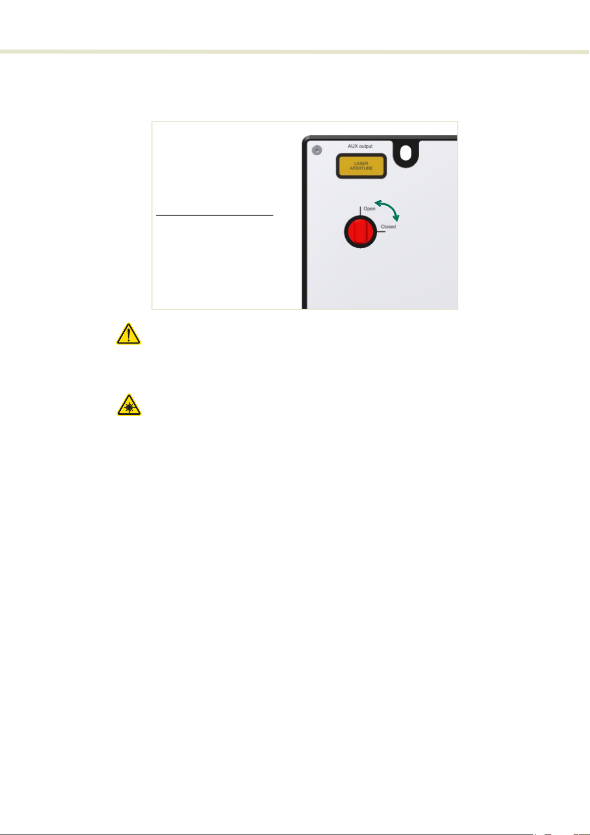
Figure 2
Auxiliary output – shutter knob set to open
Caution: When the laser outputs are not in use, NKTP recommends to CLOSE the
shutters.
Caution: You can view the position of the shutters in the status panel of CON-
TROL, see “Status Indicators” on page 31.
Warning:
When the Auxiliary output is OPEN, significant IR power can be emitted (sev-
eral watts). At this level, the power is sufficient to ignite paper, cartons, gyprock walls
and other similar items.
Warning:
The NKTP FDS is rated for 500 mW maximum. SuperK system power should
be adequately reduced when mounting an FDS (not advisable) to the Auxiliary output.
Top panel The top panel shown in Figure 3 includes the following:
• Input and output aperture indicators
• Output shutter control knobs
• Collimator release button with locking screw
• Mounting hole access
Output aperture shutters
Open – emission unblocked
Closed – emission blocked
2

15
Features
Figure 3 Top panel
Auxiliary output shutter
This shutter can be set to block or unblock the auxiliary emission output aperture.
Set the shutter to “Closed” to block emission and “Open” to unblock emission
from the aperture.
Mounting holes
The two mounting holes (2) are designed to fasten the SuperK VARIA to either
metric or imperial optical tables that have screw holes spaced at either 25 mm or
1” pitch.
Primary output shutter
This shutter can be set to block or unblock the primary filtered output emission
from the aperture. Set the shutter to “Closed” to block emission and “Open” to
unblock emission from the aperture.
Collimator release button and locking screw
SuperK laser outputs are provided with a barrel shaped collimator. When it is
inserted into an VARIA optical input receptacle, it is automatically retained by a
locking mechanism that securely holds the barrel in place. To release the
collimator from the input receptacle, press the Collimator Release button (6).
1. Auxiliary output shutter 4. Collimator locking screw
2. Mounting holes 5. Collimator release button
3. Primary output shutter 6. Electrical interfaces and LEDsi
i. See “Electrical Interfaces” on page 17
1
2
2
3
45
6

Features
16
Note: You can lock the collimator once it is in the optical input by tightening the
collimator locking screw (5).
Optical apertures Optical apertures are located on the side panels of the VARIA as shown in
Figure 4 and described in the following.
Figure 4 Optical Interfaces
Optical input aperture
The Optical input aperture is a receptacle that houses the output collimator of a
SuperK laser. The laser’s output collimator is inserted into the aperture until it
clicks and locks in place. To remove the collimator, press the release button. The
collimator can be secured by tightening the lock screw.
Caution: Do not over tighten the lock screw, doing so may damage the threads.
The optical input includes an interlock switch. If a SuperK collimator is not
inserted in the input receptacle, the switch detects this and prevents emission
(refer to Figure 5).
Primary optical output aperture
This is a free space output aperture for the primary filtered emission.
Auxiliary optical output aperture
This is a free space output aperture for the visible emission.
Monitor optical output aperture
This is a free space output aperture for power monitoring (optional).
1. Optical input aperture – see Figure 1 3. Monitor optical output aperture – with
optional cover plate mounted
2. Primary optical output aperture – with
CONNECT mounted
4. Auxiliary optical output aperture with
CONNECT mounted
23
4
1
17
Features
Note: All output apertures include 4 screw holes for mounting, for example, a fi-
ber coupler with a SuperK CONNECT accessory.
Electrical Interfaces The electrical interfaces are located on the same side panel where the optical
input aperture is located. Figure 5 shows the panel, all electrical interfaces are
located on the right side of the panel.
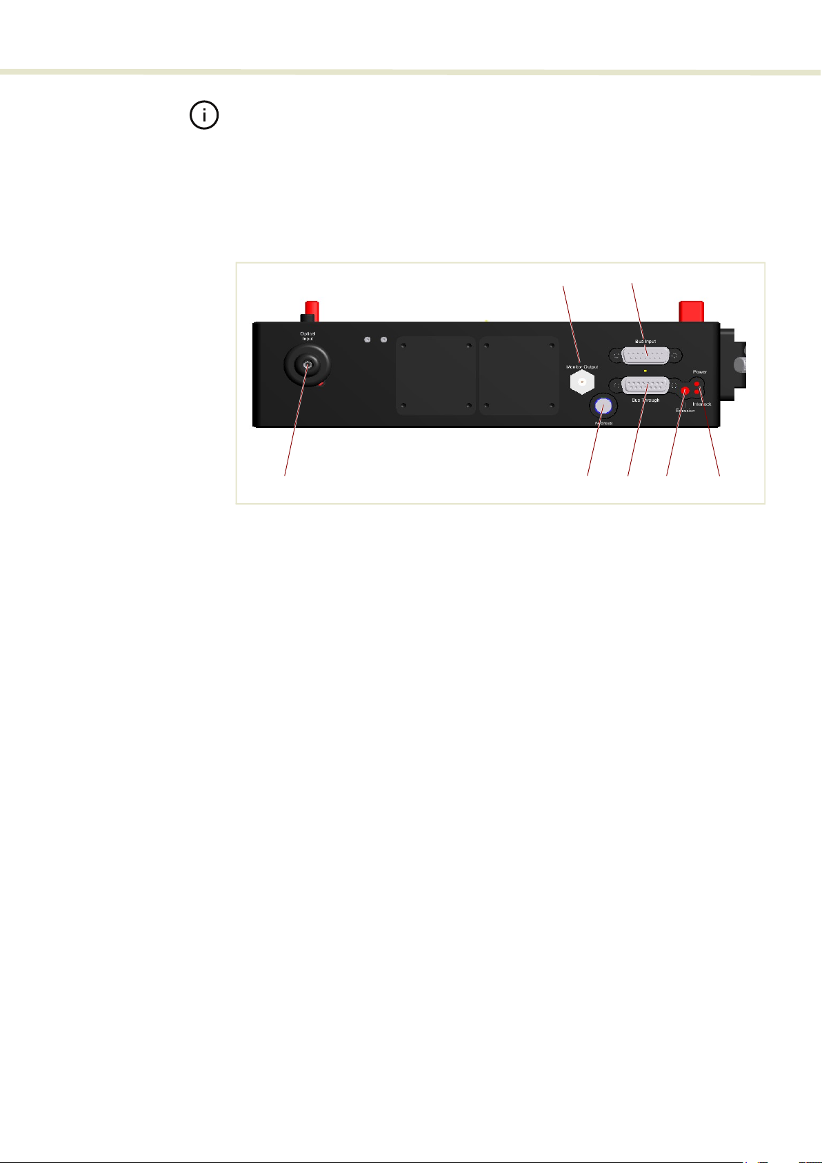
Figure 5 Electrical Interfaces and optical input
Monitor output (optional)
This port outputs an electrical signal representing the repetition rate of the laser’s
output pulse. The port is optional and only available on custom orders. Contact
NKT Photonics sales engineering for further information.
External bus input port
The bus input port connects accessories in a daisy chain with a SuperK laser.
SuperK lasers and their accessories connect using the NKTP External bus
protocol. The bus carries data communications, DC power and the interlock
signal from the laser to accessories connected on the bus.
Optical input aperture
See “Optical input aperture” on page 16.
Accessory bus address selector
When multiple accessories are connected in an External bus daisy chain, to a
SuperK laser, you can use this dial to set the bus address of the VARIA.
Accessories communicating on the same external bus must have a unique
address. The address selector dial can set the bus address with up to 16
addresses from 0x0 to 0xF (hex). You should only power on the SuperK laser and
1 Monitor output 5 Bus through output port
2 External bus input port 6 Emission LEDi
i. See “Status LEDs” on page 18
3 Optical input aperture (collimator
receptacle)
7Power and Interlock LEDsi
4 Accessory bus address selector
3 5 6 7
1
4
2

SuperK VARIA Control
18
accessories after all accessories on the External bus daisy chain are configured
with a unique address.
Bus through output port
Connects additional accessories to the External bus in a daisy chain
configuration. A bus defeater must be connected to this port if no other
accessories are used with the SuperK laser. Without a bus defeater at the end of
the accessory External bus daisy chain, the interlock loop circuit will be open and
emission disabled at the SuperK laser.
SuperK VARIA Control
Software
Description
Both the SuperK laser and the VARIA accessory are controlled using NKT Photonic’s
CONTROL management software installed on a PC or the front panel interface.
A management PC with CONTROL installed on it can connect to the laser using either
the USB serial port or the 10/100 BASE-T Ethernet port on the laser. CONTROL
communicates with the VARIA through the laser’s External bus connection.
Chapter
“CONTROL Interface”
contains information on using NKTP’s CONTROL
software and how to connect to and control the VARIA. It also includes instructions on
how to set the center wavelength to a resolution of 0.1 nm to match the intended
application.
CONTROL software installation
Refer to the procedure found in Appendix C.
Status LEDs
The VARIA includes three status LEDs as described in Table 1. The LEDs are
located on a side panel next to the External bus ports as shown in Figure 6.
The emission LED is lit ON RED when the connected SuperK laser’s emission is
enabled. When ON RED, laser light is present at the primary and auxiliary optical
output ports.
Warning:
If any of the VARIA aperture shutters are closed, emission is blocked. The
position of the shutters does not affect the status of the emission LED, only the emis-
sion status of the connected SuperK laser.

19
Status LEDs
Figure 6 Status LEDs
Table 1 Status LEDs
Warning:
DO NOT OPERATE the SuperK laser until you are familiar with the controls and
have taken all precautions necessary as described in the laser’s safety handling and
regulatory information document.
Power
Interlock
Emission
LED Name Condition Description
Emission ON RED Emission enabledi
The SuperK laser system emission is ON and class 4
emission is present at the primary and auxiliary optical
output ports.
The position of the mechanical shutters at each output
port does not change the status of the emission LED.
i. Warning: SuperK emissions are rated Class 4.
OFF Emission disabled
Power ON GREEN The VARIA is powered ON; the external bus 12V DC power
is OK.
ON RED DC supply voltage is low.
FLASHING GREEN/
AMBER
Indicates data transmission on the external bus.
OFF The VARIA is OFF; no DC power connected.
Interlock ON GREEN Interlock safety circuit is closed; laser emission permitted.
ON REDii
ii. Check the SuperK laser for interlock error information.
Interlock safety circuit is open; laser emission is disabled.

Chassis labels
20
Chassis labels
The SuperK VARIA chassis includes multiple labels that indicate hazards and
safety and product information. The labels are located on the panels as
described in Table 2 with the panels shown in Figure 7 and Figure 8.
Table 2 Chassis labels
Figure 7 Side panel manufacturing label
Label Panel Description
Class 4 Laser
Classification
Top Safety information indicating the laser
emission radiation class and
precautions to take when the laser is
operating.
Laser Aperture Top Safety information alert indicating the
location of the aperture where laser
radiation is emitted from the device.
Manufacturing Side Manufacturing information including
address, part and serial number, date
manufactured and regulatory
compliance.
Laser
Radiation
Warning
Top Safety information alert indicating this
area of the device is near a source of
dangerous laser emissions.
This manual suits for next models
1
Table of contents
Other NKT Photonics Water Filtration System manuals


Popular Water Filtration System manuals by other brands


Franklin Water Treatment
Franklin Water Treatment PKLX Series Installation instructions and owner's manual

Fiap
Fiap TrommelSieve Active Series operating instructions

Clean Water
Clean Water Living Water VORTEXer user guide

EHEIM
EHEIM Aquaball 2206 instructions

Waterway
Waterway ClearWater Series manual

PondXpert
PondXpert Triple Action Evolve 4500 How to set up