Gamma+ 6900 Els User manual

OWNER’S MANUAL
Issue 4B - February 2014
6900 Els
STRINGING MACHINE
2 POINT SC MOUNTING

3
OWNER’S MANUAL
6900 Els
LIMITED WARRANTY
GAMMA Sports (GAMMA) warrants to the original purchaser that the 6900 Els stringing machine (“EQUIPMENT”) pur-
chased is free from defects in materials and workmanship for a period of fi ve (5) years from the date of original purchase
for mechanical parts and for a period of one (1) year from the date of purchase for all electrical parts and string clamps.
Should any defects develop under normal use within the specifi ed time periods, GAMMA will at its option, repair or replace
the defective EQUIPMENT provided it is returned to GAMMA prepaid at the purchaser’s expense. This warranty does not
apply to any damage or defect caused by negligence, abuse, misuse, unauthorized alteration, shipping, handling, or part
wear and tear as a result of normal use.
Routine maintenance, adjustment, and cleaning required to ensure proper operation are the responsibility of the purchaser and
are not covered under the terms of this warranty. These include, but are not limited to: String Clamp adjustment, as described
on page 20, Quick Action Clamp Base adjustment, as described on page 20 and the cleaning procedures listed on page 21.
GAMMA’s obligation under this warranty is limited to repair or replacement of defective EQUIPMENT, and no one is authorized
to promise any other liability. GAMMA shall in no event be liable for any incidental or consequential damages.
To return defective EQUIPMENT, a return authorization (RA#) must be obtained from a GAMMA customer service representa-
tive. The RA# must be marked on the outside of the shipping carton being returned. All returns must be shipped prepaid by
the customer to GAMMA. Please retain the original shipping carton and packing materials for any future shipments. GAMMA
will not be responsible for machines which are not sent in the original undamaged packaging.
A GAMMA Care Service Plan is also available through GAMMA customer service, call 800.333.0337 for details.
TABLE OF CONTENTS
WARRANTY ................................................................................................PAGE 3
FEATURES..................................................................................................PAGE 4
UNPACKING & ASSEMBLY INSTRUCTIONS ............................................ PAGE 5
POWER CONNECTION & CONTROLS ................................................... PAGE 10
MOUNTING THE FRAME ......................................................................... PAGE 12
STRINGING THE FRAME ......................................................................... PAGE 13
ADDITIONAL FEATURES ......................................................................... PAGE 16
STRING LENGTH METER ....................................................................... PAGE 17
PATHFINDER AWL .................................................................................... PAGE 18
MAINTENANCE & ADJUSTMENTS ......................................................... PAGE 19
TROUBLESHOOTING TIPS ..................................................................... PAGE 21
PARTS LIST ............................................................................................. PAGE 22
PARTS DRAWING.....................................................................................PAGE 23

4
Electronic Constant Pull Tensioner with 11.0 to 90.0 lbs Tension
Range
Digital Tension Setting with LED Display
Professional Self-Centering Two Point Racquet Mounting Sys-
tem- Accommodates All Racquets
Parallel Jaw Rotating Gripper with Diamond Dust Coated Grip-
ping Surfaces
Professional “Quick Action” Dual Action, Rotating, Metal Fixed
String Clamps with Diamond Dust Coating
Fiberglass Cover with Convenient Padded Tool Tray enclosing
a High Strength Aluminum Frame
Convenient Foot Actuated Tensioner Switch
MACHINE FEATURES
FEATURES

5
6900 Els
Unpacking Instructions & Contents
Instructions for Unpacking and Preparing for Assembly
The stringing machine is shipped in three cartons, a large master carton for the stringing
machine base with tensioner module and accessories, a medium carton for the turntable
and mounting system and a smaller carton for the fl oor stand post and base legs. Please
save the cartons and packing materials for possible shipments in the future. Gamma
Sports cannot be responsible for machines that are not returned, shipped in their original,
undamaged packaging. The tools you will need to assemble the machine are provided
with the machine. Due to the weight of the tensioner unit, you may need the assistance of
someone to help lift the tensioner unit out of the carton.
Once the cartons are opened, remove all inner cartons and check to be sure that all parts
are present and accounted for.
Contents of Floor Stand Carton (MMU2-16)
(1) Lower Column
(1) Upper Column with Flange Plate
(4) Legs
(1) Locking Knob Screw
(4) M8 x 25 Flat Head Screws
(4) M8 x 30 Cap Screws
(8) M8 Nuts
(1) 12mm Wrench
(4) M6 x 20 Cap Screws
(1) M8 x 25 Cap Screws for Height Adjustment
(1) String Reel Holder (M8 Threaded Pin), (1) Knob, (10) Spacers, & (2) M8 Washers
Contents of Mounting System Carton (MMU2-67)
(1) Turntable Assembly w/String Clamp Bases and Mounting Stands
(2) String Clamps
(1) 17mm Socket
Contents of Large Master Carton (MMU2-12)
(1) Stringing Machine Base w/ Tensioner Module
(1) Power Cord
(1) Foot Pedal Tensioner Switch
(1) Tool Kit (contains side cutter, bent nose pliers, needle nose pliers, starting clamp)
(1) Straight Stringers Awl & (1) Pathfi nder Specialty Awl
(1) Tools for assembly and maintenance

6
Floor Stand Assembly
The stringing machine uses a four leg
fl oor stand design. The legs must be as-
sembled to the lower column before use.
Remove all parts from the shipping carton
to confi rm that contents match the list of
parts on Page 5.
ASSEMBLY INSTRUCTIONS
Floor Stand Leg Assembly
Align the holes in the leg fl ange with
the matching holes in the lower column.
Secure the leg with one M8 FLAT HEAD
screw through the upper hole, and one
M8 SOCKET HEAD cap screw through
the bottom hole. Install one 8mm nut on
each screw. Repeat this procedure for the
three remaining legs.
Floor Stand Assembly (Continued.)
To complete the fl oor stand, screw the height adjust-
ment locking knob (“A”) into the side of the lower
column. The locking knob should not protrude beyond
the inside surface of the lower column at this time.

7
Transportation Screw
The machine has been shipped with a motor
and load cell protection screw. Remove the
screw before using the machine. Retain the
screw for future shipment. Install the included
rubber grommet into the hole.
Remove this Screw
Height Adjustment
The height of the machine is adjustable
from 39” to 46” in approximate 1” incre-
ments. To change the height, remove the
socket head cap screw from its current po-
sition and place it in the appropriate hole
to set the desired height of the machine.
Be sure to thread the screw completely
into the upper column so the head of the
cap screw rests in the notch of the lower
column that is parallel to the string reel
holder.
Stand Upper Post Installation
With the height adjustment cap screw on
the upper column facing the string reel
holder, align the four holes in the upper
column fl ange with the threaded holes in
the machine base. Lift the machine base
and insert the upper post into the lower
column until the head of the cap screw
rests in the notch of the lower column and
tighten the locking knob.
ASSEMBLY INSTRUCTIONS

8
String Clamp Installation
The post of the string clamp and tube of the
string clamp base are treated with grease to
provide protection against corrosion during
shipping. Remove any excessive grease with
a clean cloth prior to use. The post and tube
may also be cleaned with isopropyl alcohol.
After this type of thorough cleaning, the post
and tube should be treated with a light coating
of machine oil to protect the surfaces against
corrosion and to ensure smooth operation.
ASSEMBLY INSTRUCTIONS
String Length Meter Wire Installation
Connect the black string length meter wire
to the receptacle in the black FRP base and
to the back of the tensioner.
Turntable and Mounting System
Installation
To install the turntable position the turntable
over the turntable pin and align the bolts,
located in the poly bag, with the holes in
the fl ange. Secure them with the included
allen wrench.

9
The string reel holder is an 8 mm rod with
threads on both ends, and fl at surfaces
machined on one end. Thread the end of
the rod without the fl at surfaces into the
threaded boss on the side of the lower
column. Using the M6 open end wrench
positioned on the fl at surfaces, securely
tighten the rod to the lower column.
After the last reel is installed, place the
remaining spacer(s) on the rod and attach
the threaded knob to the end of the rod.
The string reel holder can hold up to 5
reels of string (depending on the size of
the string reel). Before placing the fi rst reel
on the rod, slide two M8 washers over the
pin and slide them to the boss on the lower
column. After the fi rst reel is placed onto
the rod, place two spacers between each
reel to provide enough space between
reels and allow them to turn freely without
rubbing against one another. (To provide
a smooth feed to the String Length Meter,
place the reels on the rod so the string
spools off the reel from the underside of
the reel).
STRING REEL HOLDER INSTALLATION

10
POWER CONNECTION & CONTROLS
Front Panel Features
A - String Gripper
B - Tension Switch
C - Control Panel
Back Panel Features
A - Lighted Power Switch
B - Foot Pedal Switch Receptacle
C - A/C Power Cord Socket
D - String Length Meter Socket
B
C
A
C
B
A
Instructions for Power Connection and Controls
CAUTION ! Before connecting to the power supply, check the voltage source that the
machine is being connected to. The acceptable range of input voltages for this ma-
chine is between 100 V and 240 V @ 50 to 60 Hz. If you have any questions regarding
the input voltage supply for your area, please ask your electric utility company.
To install the power cord, insert the female end of the power cord into the AC Adapter and
then insert the female end of the cord from the AC Adapter into the A/C Power Cord Socket
“C” located on the back panel of the tensioner. Plug the male end of the power cord into a
grounded power outlet. When using extension cords, use grounded heavy duty extension
cords rated for 15 AMP service.
To connect the foot pedal switch, insert the male pin at the end of the foot pedal switch cord
into the Foot Pedal Switch Receptacle “B” located on the back panel of the tensioner.
Switch on the machine by pressing the Lighted On-Off Power Switch on the back panel. At
start-up, the LED will display a countdown from “9.0” to “0.0” while the machine performs a
self diagnostics check at start-up.
D
WARNING! FOR INDOOR USE ONLY.
NEVER OPEN UNIT WITH POWER CONNECTED.
CHILDREN SHOULD NEVER BE PERMITTED TO OPER-
ATE THIS MACHINE WITHOUT ADULT SUPERVISION.

11
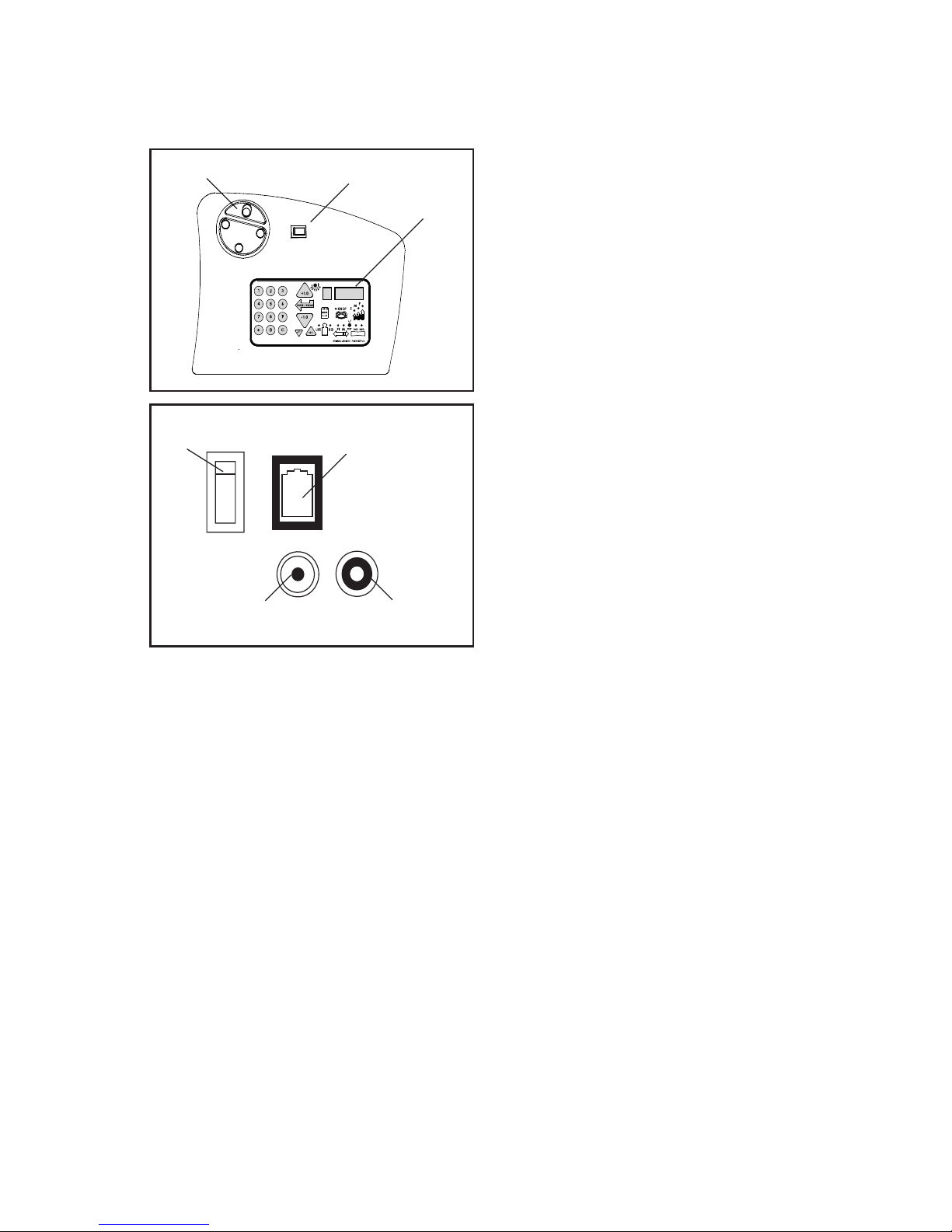
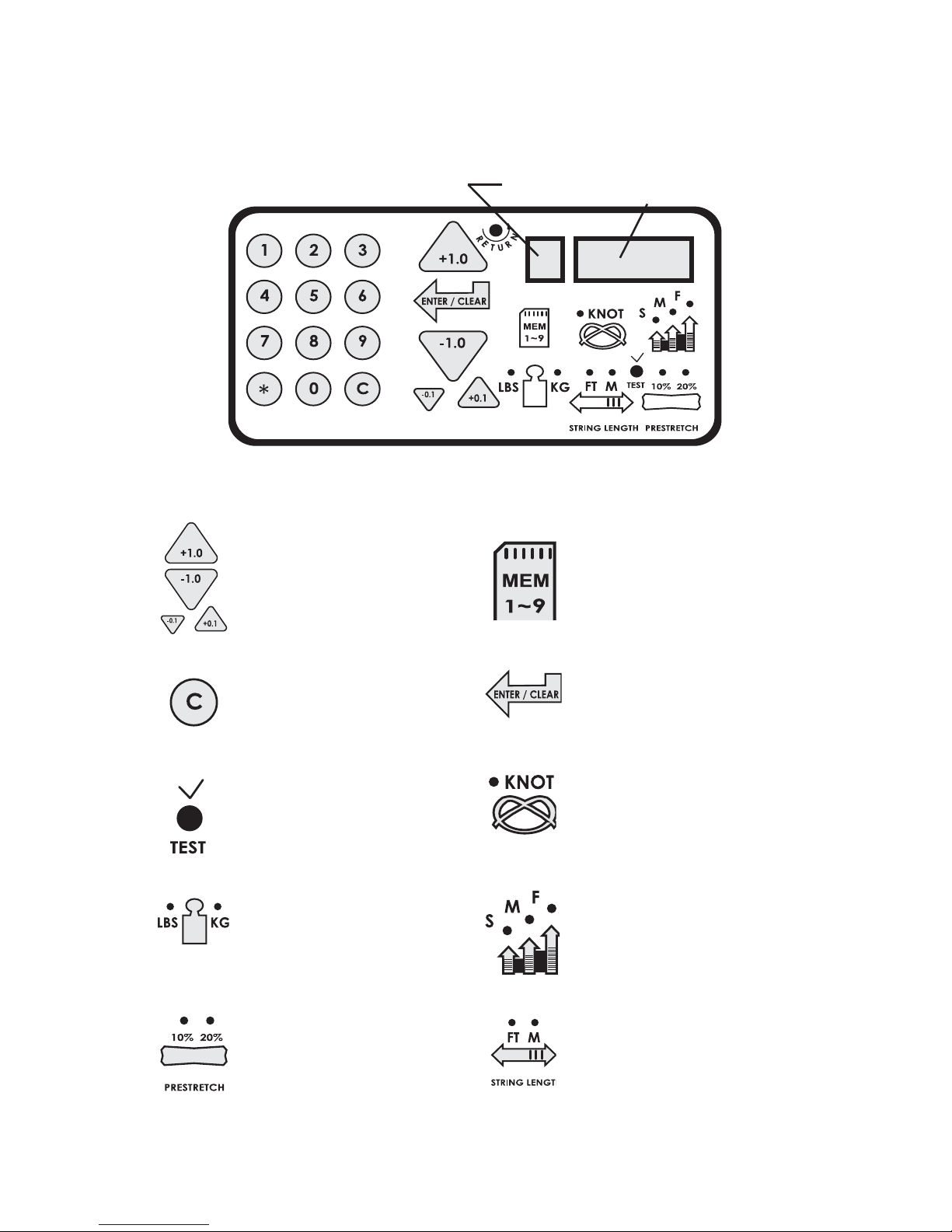
CONTROL PANEL FUNCTIONS
AND FEATURES
Single Digit (1-9)
Memory LED Display
Three Digit (XX.X)
Tension Setting Dis-
play or String Length
LED Display
String Length Meter Button- Enables
string length meter function. Each press
of the button toggles between Meters
and Feet. To switch back to tensioning
function, press the “Lbs/Kgs” button.
Lbs/Kgs Button - Changes tension
display from Lbs to Kgs. Each press
of the button toggles back and forth
between Lbs and Kgs.
Speed Button - Changes pulling speed
of winder from Fast (default) to Medium
to Slow. Slow speed is recommended
for low stretch strings, such as Kevlar.
Each press of the button toggles be-
tween Fast, Medium and Slow speeds.
Pre-Stretch Function - Pulls string 10%
or 20% over the tension setting (up to 90
lbs / 40.8 kgs), releases the string, and
repulls to the tension setting. Each press
of the button toggles between 10%, 20%
or no pre-stretch.
Clear Button - Clears display to enter
a new tension or to reset String Length
Meter measurement.
Knot Function - Increases pulling ten-
sion by 10% over the setting value (max
90 lbs / 40.8 kgs) for one pull. During the
pull the LED stays lit to indicate the Knot
function is enabled.
Tension Index Buttons - Changes
tension setting in +/- 1.0 or +/- 0.1 Lb or
Kg increments. Holding the button down
will scroll the tension setting values up
or down. Tension settings entered with
the tension index buttons are placed into
temporary memory setting “0”.
Memory Button - Indexes from 9 preset
tension settings that can be stored in
memory. Settings are retained even if
machine is turned off. Each press of
the button indexes to the next memory
setting. Memory settings 1-9 must be
entered using the keypad followed by
pressing the “ENT” button.
Enter Button - Saves displayed tension
for Memory setting - when tension is en-
tered using the keypad display fl ashes
until this button is pressed to save the
setting. Also Clears display for String
Length Meter measurements.
Test Button & Racquet Strung -
Press once for approximate number of
racquets strung. Press again to return.
Press and hold for 5 seconds and the
machine does an internal diagnostic
check, such as the one performed at
start-up.
Other manuals for 6900 Els
2
Table of contents
Other Gamma+ Stringing Machine manuals

Gamma+
Gamma+ Progression 602 FC User manual

Gamma+
Gamma+ 5003 User manual

Gamma+
Gamma+ Progression 600 User manual

Gamma+
Gamma+ 5003 User manual

Gamma+
Gamma+ 8800 Els User manual

Gamma+
Gamma+ 5002 User manual

Gamma+
Gamma+ 6900 Els User manual

Gamma+
Gamma+ PRO 100 User manual

Gamma+
Gamma+ X-6 User manual

Gamma+
Gamma+ Progression 200 User manual

Gamma+
Gamma+ X-ST User manual

Gamma+
Gamma+ Progression 602 FC User manual

Gamma+
Gamma+ 5800 Els User manual

Gamma+
Gamma+ 6004 User manual

Gamma+
Gamma+ Progression STII User manual

Gamma+
Gamma+ 8800 Els User manual

Gamma+
Gamma+ X-ST User manual

Gamma+
Gamma+ 5800 Els User manual

Gamma+
Gamma+ 5003 User manual

Gamma+
Gamma+ 6004 User manual


