Gamma+ 8800 Els User manual

OWNER'S MANUAL
Issue 2 - January 2009
STRINGING MACHINE
8800 Els
6 POINT MOUNTING

1
LIMITED WARRANTY
GAMMA SPORTS warrants to the original purchaser that the 8800 Els stringing machine ("EQUIPMENT") purchased is free
fromdefectsinmaterialsandworkmanshipforaperiodoffive(5)yearsfromthedateoforiginalpurchaseformechanicalparts
(excluding electrical parts and string clamps), and for a period of one (1) year from the date of purchase for all electrical parts
and string clamps. Should any defects develop under normal use within the specified time periods, GAMMA will at its option,
repair or replace the defective EQUIPMENT provided it is returned to GAMMA prepaid at the purchaser's expense. This
warranty does not apply to any damage or defect caused by negligence, abuse, misuse, unauthorized alteration, shipping,
handling, or part wear and tear as a result of normal use.
Routine maintenance, adjustment, and cleaning required to ensure proper operation are the responsibility of the purchaser
and are not covered under the terms of this warranty. These include, but are not limited to: String Clamp adjustment, as
described on page 18, Switch Action Clamp Base adjustment, as described on page 18, and the cleaning procedures listed
on page 19.
GAMMA’sobligationunderthiswarrantyislimitedtorepairorreplacementofdefectiveEQUIPMENT,andnooneisauthorizedto
promiseanyotherliability.GAMMAshallinnoeventbeliableforanyincidentalorconsequentialdamages.
ToreturndefectiveEQUIPMENT,areturnauthorization(RA#)mustbeobtainedfromaGAMMAcustomerservicerepresentative.The
RA#mustbemarkedontheoutsideoftheshippingcartonbeingreturned.Allreturnsmustbeshippedprepaidbythecustomer
to GAMMA. Please retain the original shipping carton and packing materials for any future shipments. GAMMA will not be
responsible for machines which are not sent in the original undamaged packaging.
An Extended Warranty is available through a GAMMA customer service representative, call 800.333.0337 for details.
TABLE OF CONTENTS
PAGE 1................................................................................................ WARRANTY
PAGE2 ...................................................................................................FEATURES
PAGE3 .........................................................................UNPACKING&ASSEMBLY
PAGE8 ......................................................... POWERCONNECTION&CONTROLS
PAGE10 ........................................................ TENSIONER&GRIPPEROPERATION
PAGE11 ............................................................................ MOUNTINGTHEFRAME
PAGE13 ............................................................................STRINGINGTHEFRAME
PAGE15 ...................................................... STRINGLENGTHMETEROPERATION
PAGE16 ...........................................................................ADDITIONALFEATURES
PAGE17 .................................................................................... PATHFINDERAWL
PAGE18 ................................... MAINTENANCE,ADJUSTMENTS&CALIBRATION
PAGE20 ........................................................................ TROUBLESHOOTINGTIPS
PAGE21 ...............................................................................................PARTSLIST
PAGE22 ..................................................................................... PARTSDRAWING
OWNER'S MANUAL
8800 Els

2
MACHINE FEATURES
Electric Constant Pull Tensioner w/ 11 lbs. to 89 lbs. Tension
Range
Digital Tension Setting Display
Professional Six Point Self-Centering “Suspension Mount”
Racquet Mounting System- Accomodates All Racquets
Without Adapters
Parallel Jaw Linear Gripper w/ Diamond Dust Coated Gripping
Surfaces
Professional Dual Action, Rotating, Diamond Dust Coated,
Fixed String Clamps
High Strength Extruded Aluminum Frame with Durable
Anodized Finish and a Convenient Padded Tool Tray
Unique Internal Drawer System for Storing Tools and Adap-
tors.
Convenient Foot Actuated Tensioner Switch
FEATURES

3
8800 Els
Unpacking Instructions & Contents
Instructions for Unpacking and Preparing for Assembly
The stringing machine is shipped in three cartons, a large master carton for the stringing
machine base with tensioner module and accessories, a medium carton for the turntable
and mounting system and a smaller carton for the floor stand post and base legs. Please
save the cartons and packing materials for possible shipments in the future.
Gamma Sports cannot be responsible for machines that are not returned, shipped in their
original, undamaged packaging. The tools you will need to assemble the machine are
provided with the machine. Due to the weight of the tensioner unit, you may need the
assistance of someone to help lift the tensioner unit out of the carton.
Once the cartons are opened, remove all inner cartons and check to be sure that all parts
are present and accounted for.
Contents of Floor Stand Carton
(1) Lower Column
(1) Upper Column with Flange Plate
(4) Legs
(1) Locking Knob Screw
(4) M8 x 25 Flat Head Screws
(4) M8 x 30 Cap Screws
(8) M8 Nuts
(6) M6 x 20 Cap Screws
(1) M8 x 25 Cap Screws for Height Adjustment
(1) String Reel Holder (M8 Threaded Pin), (1) Knob, (10) Spacers, & (2) M8 Washers
Contents of Mounting System Carton
(1) Turntable Assembly w/String Clamp Bases and Mounting Stands w/ Frame Support
Slide, Side Supports, and Adapters
(2) String Clamps
(1) Package of Spare plastic adapters for mounting system supports (contains 16 pcs)
Contents of Large Master Carton (including accessory cartons packed inside)
(1) Stringing Machine Base w/ Tensioner Module
(1) Power Cord
(1) Foot Pedal Tensioner Switch
(1) Tool Kit (contains side cutter, bent nose pliers, needle nose pliers, starting clamp)
(1) Straight Stringers Awl & (1) Pathfinder Specialty Awl
(1) Tools for assembly and maintenance

FloorStandAssembly
The stringing machine uses a four leg floor
stand design. The legs must be assembled
to the lower column before use. Remove all
partsfromtheshippingcartontoconfirmthat
contents match the list of parts on Page 3.
FloorStandLegAssembly
Align the holes in the leg flange with the
matching holes in the lower column. Secure
the leg with one M8 FLAT HEAD screw
throughtheupperhole,andoneM8SOCKET
HEAD cap screw through the bottom hole.
Install one 8mm nut on each screw. Repeat
this procedure for the three remaining legs.
ASSEMBLY INSTRUCTIONS
FloorStand Assembly(Cont.)
To complete the floor stand, screw the height adjust-
mentlockingknob(“A”)intothesideofthelowercolumn.
The locking knob should not protrude beyond the inside
surface of the lower column at this time.
“A”
4

ASSEMBLY INSTRUCTIONS
5
HeightAdjustment
Theheightofthe machineisadjustablefrom
39” to 46” in approximate 1” increments. To
change the height, remove the socket head
cap screw from its current position and
place it in the appropriate hole to set the
desired height of the machine. Be sure to
thread the screw completely into the upper
column so the head of the cap screw rests
in the notch of the lower column.
FloorStandUpperColumnInstallation
(cont.)
Securetheflangetothebaseofthemachine
with the six M6 cap screws packed with the
floor stand.
USECAUTIONWHENSECURINGSCREWS
TO SLIDE BRACKETS. CROSS THREAD-
INGOROVERTIGHTENINGMAYDAMAGE
THETHREADSINTHESLIDEBRACKETOR
CAUSETHETHREADSTOSTRIPOUT.
StandUpper PostInstallation
Withthe heightadjustment capscrew onthe
upper column facing the brake lever & string
length meter, align the six holes marked “X”
intheupper columnflangewiththe threaded
holes in the slide brackets of the machine
base.

6
STRING REEL HOLDER INSTALLATION
The string reel holder is an 8 mm rod with
threads on both ends, and flat surfaces
machinedon oneend. Threadtheend ofthe
rodwithouttheflatsurfacesintothethreaded
boss on the right side of the lower column.
UsingtheM6openendwrenchpositionedon
the flat surfaces, securely tighten the rod to
the lower column.
The string reel holder can hold up to 5 reels
of string (depending on the size of the string
reel). Before placing the first reel on the rod,
slide two M8 washers over the pin and slide
them to the boss on the lower column. After
thefirst reelisplaced ontothe rod,placetwo
spacers between each reel to provide
enough space between reels and allow
them to turn freely without rubbing against
one another. (To provide a smooth feed to
the String Length Meter, place the reels on
the rod so the string spools off the reel from
the underside of the reel.)
After the last reel is installed, place the
remaining spacer(s) on the rod and attach
the threaded knob to the end of the rod.

7
ASSEMBLY INSTRUCTIONS
String Clamp Installation
The post of the string clamp and tube of the string
clamp base are treated with grease to provide protec-
tion against corrosion during shipping and while in
storage. Remove any excessive grease with a clean
cloth prior to use. The post and tube may also be
cleaned with isopropyl alcohol. After this type of
thoroughcleaning,thepostandtubeshouldbetreated
with a light coating of machine oil to protect the
surfaces against corrosion and to ensure smooth
operation.
Turntable and Mounting System In-
stallation
To install the turntable remove the four nuts
underneath holding the mounting bolts in
place. Position the turntable over the turn-
table pin and align the bolts with the holes in
the flange. Secure them with the included
allen wrench.

8
POWER CONNECTION & CONTROLS
FrontPanelFeatures
A - String Gripper
B - Tension Button
C - ControlPanel
D - L.E.D.TensionDisplay
BCAD
Instructions for Power Connection and Controls
CAUTION ! Before connecting to the power supply, check the voltage source
that the machine is being connected to. The acceptable range of input volt-
ages for this machine is between 100 V and 240 V @ 50 to 60 Hz. If you have any
questions regarding the input voltage supply for your area, please ask your electric
utility company.
To install the power cord, insert the female end of the power cord into the AC Adapter
and then insert the female end of the cord from the AC Adapter into the A/C Power Cord
Socket “C” located on the back panel of the tensioner. Plug the male end of the power
cord into a grounded power outlet. When using extension cords, use grounded heavy
duty extension cords rated for 15 AMP service.
To connect the foot pedal switch, insert the male pin at the end of the foot pedal switch
cord into the Foot Pedal Switch Receptacle “B” located on the back panel of the tensioner.
Switch on the machine by pressing the Lighted On-Off Power Switch on the back panel. At
start-up, the LED will display a countdown from “9.0” to “0.0” while the machine performs a
self diagnostics check at start-up.
WARNING! FOR INDOOR USE ONLY. TO BE USED BY
ADULTS OR UNDER ADULT SUPERVISION ONLY.
NEVER OPEN UNIT WITH POWER CONNECTED.
Back Panel Features
A - Lighted Power Switch
B - A/C Power Cord Socket
C - Foot Pedal Switch Receptacle
D - String Length Meter Receptacle
BCDA

9
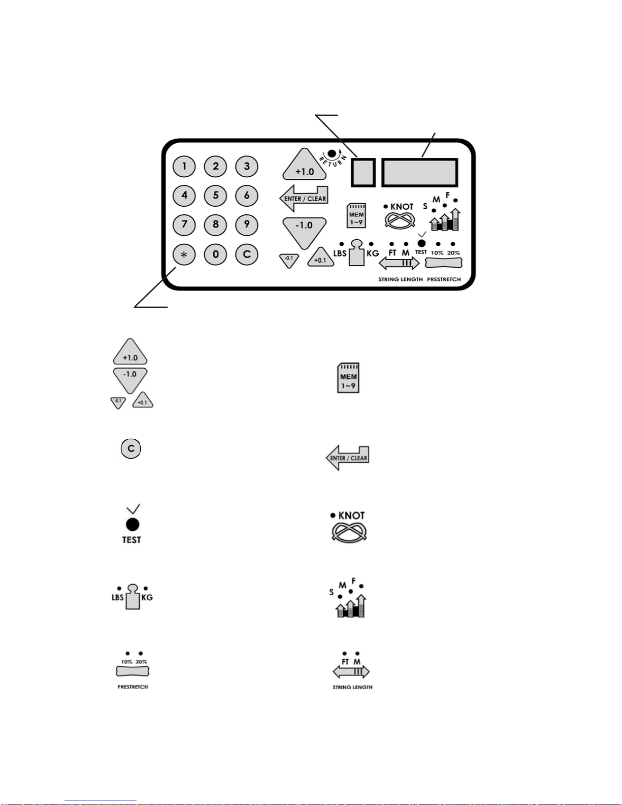
CONTROL PANEL FUNCTIONS
AND FEATURES
Single Digit (1-9)
Memory LED Display
Three Digit (XX.X)
Tension SettingDisplay
or String Length LED
Display
12 Button Keypad - Usedto entertensionsettings
Lbs/Kgs Button - Changes tension
display from Lbs to Kgs. Each press of
the button toggles back and forth
between Lbs and Kgs.
Speed Button - Changes pulling speed
of winder from Fast (default) to Medium
to Slow. Slow speed is recommended
for low stretch strings, such as Kevlar.
Each press of the button toggles
between Fast, Medium and Slow
speeds.
Pre-Stretch Function - Pulls string
10% or 20% over the tension setting (up
to 90 lbs / 40.8 kgs), releases the string,
and repulls to the tension setting. Each
press of the button toggles between
10%, 20% or no pre-stretch.
String Length Meter Button - Enables
string length meter function. Each press
of the button toggles back and forth
between Meters and Feet measure-
ment. To switch back to tensioning
function, press the “Lbs/Kgs” button.
Clear Button - Clears display to enter a
newtensionor toreset StringLength
Metermeasurement
Knot Function - Increases pulling tension
by 10% over the setting value (max 90 lbs /
40.8 kgs) for one pull. During the pull the
LED stays lit to indicate the Knot function is
enabled.
Tension Index Buttons - Changes
tensionsetting in+/-1.0 or+/-0.1 Lbor
Kgincrements.Holdingthebutton down
will scroll the tension setting values up
or down. Tension settings entered with
the tension index buttons are placed
into temporary memory setting “0”.
Memory Button -Indexesfrom9 preset
tension settings that can be stored in
memory. Settings are retained even if
machine is turned off. Each press of the
button indexes to the next memory setting.
Memorysettings1-9 must beentered using
thekeypadfollowedbypressingthe“ENT”
button.
Enter Button -Savesdisplayedtension for
Memorysetting-when tension isentered
usingthekeypaddisplayflashesuntilthis
buttonispressedtosave the setting.Also
Clearsdisplay forStringLength Meter
measurements
Test Button & Racquet Strung - Press
onceforapproximatenumberofracquets
strung. Pressagain toreturn. Pressand
holdfor5secondsandthemachinedoes
aninternaldiagnosticcheck, suchas the
oneperformedatstart-up.

10
TensioningaString
After wrapping the string around the roller
guide and guiding it between the gripper
jaws, while gently pulling the string perpen-
dicular to the gripper plates, press the
tensioning lever switch at the end of the
gripper or press the foot pedal switch to
activate the tensioner. The tensioner will
start pulling at full speed and then slow
downasthetensioninthestringapproaches
the tension setting. When the tension in the
string reaches the tension setting, the LED
display will begin to flash, and the string will
be ready to clamp off. In the event that one of the keys on the control panel are accidently
pressed while tensioning a string, the tensioner will automatically reverse and release the
string being tensioned.
TENSIONER OPERATION
TensioningLever
Switch
StringGripperOperation
Toinsertastringintothelinearstringgripper,
wrap the string clockwise around the roller
guide and insert the string between the
diamond dust coated string gripper plates.
Excessive slack in the string should be
removed before applying tension. Pull the
stringperpendiculartothegripperplatesand
begin tensioning. As tension is applied, the
grippers will engage to hold the string. For
adjustmentoftheparallelplates,see“Setting
the Gripper Plate Spacing” on page 17.
CAUTION ! CHILDREN SHOULD NEVER BE PERMITTED TO OPERATE THIS MACHINE
WITHOUTADULTSUPERVISION.
STRING GRIPPER OPERATION
Settingthe StringTension
String tensions may be entered and stored
into one of nine memory storage settings
(See section on Control panel Functions
and features) by using the keypad or ten-
sion index buttons. While tension setting is
entered, the value displayed will be tempo-
rary until the “Enter” button is pressed to
storeitinoneoftheninepermanentmemory
settings.

11
STRING CLAMPS
StringClampOperation
The string clamps are a dual action design
where the string clamp and clamp base
operate independently of one another.
To clamp a string, lift the clamp head and
place the string between the jaws and de-
press the string clamp lever to secure the
string.The clampingpressure appliedtothe
string should be adjusted as needed (see
Page 18) to provide sufficient pressure to
secure the string when subjected to the
desiredpullingtension.Thediamondcoated
gripper plates provide for increased friction
between the clamps and the string to allow for reduced clamping pressure while securing
and holding the string under tension.
MOUNTING THE FRAME
MountingStandAdjustment
Position the racquet frame over the mount-
ing stands and adjust the spacing between
thestands sothe postsof theframesupport
slides fit inside the head of the racquet. By
turning one of the knobs located at either
end of the turntable counter clockwise the
the stands move closer together. Turning
clockwise will increase the separation be-
tween the stands. With the stands posi-
tioned so the posts of the frame support
slides are completely within the head of the
racquet frame, turn one of the knobs clockwise until they contact the inside of the racquet
head at 6 and 12 o’clock.
Clamp Base Operation
Rotate the base locking lever clockwise to
secure the clamp base to the turntable and
counter clockwise unlock the string clamp.
The locking lever is spring loaded to assist
the unlocking of the clamp base.
The locking lever should be adjusted to
prevent clamp base slippage on the turn-
table, when the desired tension is placed on
thestring,whilepermittingtheclampbaseto
slide freely on the turntable when the lever
is disengaged.
Instructions for adjustment of the clamp base locking lever can be found on Page 17.

12
MOUNTING THE FRAME
ShoulderSupportAdjustment
The shoulder supports are designed to ro-
tateandcanbeadjustedtoprovidemaximum
support to the racquet frame. Rotate the
support so that the pads contact the frame
squarely when the arms are closed against
the racquet. Should the shoulder supports
block string holes, adjust the frame support
slidesto re-positiontheracquet betweenthe
armssotheshouldersupports makecontact
with the racquet between grommet holes.
SecuringtheShoulder Supports
To secure the racquet frame with the shoul-
der supports, rotate the large adjustment
knobsonthe outsideof themounting stands
clockwise to bring the mounting arms to-
gether. Adjust until firm contact is made
between the shoulder supports and the
frame.
The tear drop shaped holes torwards the
back of the shoulder supports are handy for
holding the loose end of the string while
pullingthestringthroughtheracquet.Simply
insertthelooseendintotheteardropshaped
holesand slidethestring intothepoint ofthe
hole.
FrameSupportSlideAdjustment
The Frame Support Slide need only be adjusted
if the shoulder supports are blocking a
grommet hole. Do not extend the Frame
Support Slide beyond the machined line located
on the Support Slide.
Apply a final adjustment to all racquet support
points until the racquet is firmly secured in the
mounting system.
Should the frame supports lose contact with the
frame while stringing, they should be re-
adjusted, as needed, to maintain contact with
the racquet frame.

13
PullingTension
To apply tension, wrap the string being
tensioned clockwise around the roller guide
and position the string between the gripper
jaws.
The string must pass over the roller guide
before being placed between the gripper
jaws to ensure that the proper tension is
applied to the string.
Pullthestringuntilallslackisremovedbefore
pressing the tension lever switch.
STRINGING THE FRAME
Getting Started
To begin installing the main strings, thread
the two ends of the string through the two
center holes at the appropriate end of the
frame and continue through the opposite
center holes. Thread one end of the string
through the adjacent grommet hole and pull
excess by hand.
Secure one of the strings using a string
clamp.
WARNING: KEEP FINGERSAWAY FROM ROLLER
GUIDE WHILE TENSIONING STRING. TO RELEASE
TENSION BEING APPLIED TO THE STRING PRESS THE
PUSH TENSION LEVER SWITCH OR ANY BUTTON ON
THE KEYPAD IN CASE OF EMERGENCY.
To apply tension to a string, press the
tension lever switch or the foot pedal
switch. The string gripper will move to the
right, away from the racquet, and gradu-
ally apply tension to the string. When the
set tension has been attained, the gripper
will stop moving. As the tensioned string
relaxes, the gripper will continue to pull
intermittently, to maintain the set tension.
Toreleasethe stringafterclamping,press
the tension lever switch or foot pedal
switch. If the string gripper does not re-
lease the string, push the gripper plates to
the right to help disengage and release the string from the gripper.
TensionLever
Switch

14
Clamping the First Main String
Secure the tensioned main string using the
remaining fixed clamp. Repeat the proce-
dureforalloftheremainingmainstringsand
tie off following the racquet manufacturers
recommendations.
Follow the manufacturer's recommended
stringing pattern for one or two piece string-
ing. This will determine the starting point for
the cross strings. If applicable, tie the first
cross string using an appropriate starting
knot.
STRINGING THE FRAME
Weaving the Cross Strings
Weave the cross strings over and under the
main strings being careful to alternate the
weave direction of each consecutive cross
string so as to be opposite of the previously
installed cross string.
CompletingtheStringJob
Once the final cross string is tensioned and
clamped, tie off at the appropriate hole
specified by the racquet manufacturer.
Remove the frame from the mounting sys-
tem by loosening the shoulder supports and
frame supports.

15
To enable the String Length Meter (SLM)
function, press the String Length button on
the keypad. When the String Length button
is pressed, one of the LED indicators above
“M” or “FT” will light up to indicate that the
SLMfunctionisenabled.Pressing theString
Length button will toggle between “M” and
“FT” to set the measurement units for either
Meters (“M”) or Feet (“FT”). Measurements
are displayed in 0.1 increments.
To measure a length of string from a reel or
set of string, insert the end of the string
through the loop from the backside of the
stringguide attachedto thefront ofthe SLM.
Lift the clamp pad and insert the string
throughtheentryholeonthefaceplateofthe
SLM.Continuetofeedthestringintotheentry
holeuntilitexitstheSLMthroughtheholeon
the right side and release the clamp pad. (In
addition to aligning the strings with the entry
totheSLM, thefeltclamppadsapply aslight
amount of pressure to the string and wipe
down the surface of the string to prevent
debris from entering the SLM).
When the end of the string exits through the
hole on the right, press the “C” or “Entry/
Clear” button on the keypad to “Zero” the
display, and the length of string will be
measuredfromthepointonthestringlocated
attheedgeoftheexithole.Pulltheendofthe
string at a slow steady rate and the SLM will
begin measuring the length of string as it is
pulled through the SLM and indicate the
measurementon theLED display.When the
desired length of string is measured, cut the
string at the edge of the exit hole.
NOTE:Whenreaching the endofa string,
pull the string through the SLM slowly
to avoid inaccurate measurement.
The string length meter was designed to measure strings between 1.10 mm (18 ga) and 1.45
mm(15ga)atanaccuracyof+/-0.3%oftheindicatedvalueand+/-2inches(50mm)absolute.
When measuring strings smaller than 1.10 mm (such as badminton strings) the error will be
-2.5% of the indicated value (up to 6” short in 40 ft) and +/- 2 inches (50 mm) absolute.
STRING LENGTH METER OPERATION
SLM button

16
Storage Drawers
There are two storage drawers located in
the base of the machine. The drawers open
from the right side of the base and lock into
the end cap with a spring loaded latch.
To open the drawers depress that latch in
thefaceofthedrawerandslideittotheright.
To close the drawer simply slide the drawer
back inside the base and the latch with
automatically lock into place.
ADDITIONAL FEATURES
CuttingBlock
A cutting block is provided as a convenient
surface for cutting a point or sharp edge on
theendofastringusingarazorbladecutter.
Turntable Brake
Theturntable maybe lockedinanyposition.
Flipthe leverto therighttolockthe turntable
brake and flip the lever to the left to release
the turntable brake.

17
PATHFINDERAWL
Once the awl is inserted, pull the handle of
the awl outward while holding the tip section
in place, leaving the outer sheath in the
grommethole. Inserttheendofthestringinto
the center of the sheath.
While holding pressure on the string, slowly
pull the sheath out of the grommet hole to
leave the end of the string exposed.
The machine includes the Pathfinder string-
ing awl which creates a pathway between
or around strings to make inserting a string
through tight grommets easier and quicker.
Insert the awl through the grommet hole in
the same manner as for traditional awls.
The Pathfinder awl must be in the closed
position before insertion.

18
GripperPlateSpacingAdjustment
Theparallelplatesofthestringgripperareadjust-
able to accomodate varying string gauges and
types of string. If the string slips through the
gripper plates while pulling tension, rotate the
gripper adjustment screw counter-clockwise. If
thestringisdamagedwhilepullingtension,rotate
the gripper adjustment screw clockwise. The
gripperisproperlyadjustedwhenthereisenough
pressure to securely hold the string without
causing damage to the string. If you move the
grippertotherighthandendofthetrackitiseasier
to access the screw.
TensionCalibrationProcedure
Each stringing machine has been
checked and calibrated at the factory
using accurate load sensing devices
toensurethat themachine pullsat the
correct tension. However, if you sus-
pect that your machine may not be
pulling at the correct tension you can
check the pulling tension with a cali-
bratorandmakeadjustmentsifneeded.
Most tension calibrators (such as a Gamma Tension Calibrator) function by clamping off the
string attached to one the end of the calibrator and applying tension to the string located
ontheoppositeendofthecalibrator.Thetensionmeasuredbythecalibratorwillthendisplay
the tension being applied to the calibrator by the machine. If the calibrator and tensioner
do not match then you can adjust the tensioner as follows:
(1) Turn the machine off and restart the machine while holding down the Test buttonuntil
count down is complete. 22 lbs should appear on the display. (2) Apply tension to the
calibrator. (3) If the tension reading on the calibrator does not match the tension displayed
onthemachine,usethetensionindexingbuttonstomatchthedisplaytothecalibratorreading
and press the Enter/Clear button (4) Release the tension applied to the calibrator and 44 lbs
shouldappearonthe display.(5)Repeatsteps#2-#4for 44,66&88lbs. (6)Aftercompleting
the adjustment at 88lbs the display will show 00 lbs. (7) Restart the machine without holding
any buttons and the calibration adjustment will be complete.
MAINTENANCE & ADJUSTMENTS
SwitchActionClampBaseAdjustment
If the clamp bases slip on the turntable, the
base locking levers may need adjusted. Turn
the cap screw located on the end of the clamp
base clockwise to tighten the clamp and coun-
terclockwise to loosen it. If frequent adjust-
mentisneeded, trylooseningthelockinglever
adjustment screw and tighten the two screws
located on the underside of the clamp base.
Re-tighten the locking lever adjustment screw
and adjust as needed.
AdjustmentScrew

19
MAINTENANCE & ADJUSTMENTS
AdjustingtheString Clamp JawSpacing
The string clamps will need minor adjustments according
to what string type, construction, and gauge you are
using.
Toadjustthegap(clampingpressure)betweentheclamp
jaws, insert the string through the racquet as if you were
beginning the main strings. Clamp the strings and pull
tension. If the string slips through the jaws of the clamp,
tightentheclampbycompressingtheclampjawstogether
by hand while turning the Adjustment Knob, in the clock-
wise direction. If the clamp leaves impressions or dam-
ages the string, it may be excessively tight and should be
adjustedby turningtheAdjustment Knobcounterclockwisetoopenthegap betweenthejaws.
The clamp jaws should be cleaned periodically to be free from dirt, oil, and any string coating
for them to grip properly. Knife sharpening stones are excellent for removing build-up on the
diamond coated surfaces and are provided with the machine. Replacements are available.
Note: The string clamps supplied with your stringing machine can accomodate tight string
patternssuchasbadminton.Dependingonthestringpattern,theclampmayspreadthestrings
slightly which will not compromise the quality of the string job. String clamps designed
specifically for badminton racquets are included with the machine.
Adjustment
Knob
Switching the Buzzer Off and On
The stringing machine is equipped with a buzzer that sounds when any key or button is
pressed,whenthe tensionerhas pulleda stringto theend ofitstravel andis notyet attension,
or when there is a problem with the some fucntion of the machine. The buzzer can, however,
be disabled if desired for normal keypad entries.
To disable the buzzer, turn the machine on and while the display is counting down from 9 to
0, press and hold the Enter/Clear button for at least 5 seconds. The buzzer will be disabled
and will remain disabled. It can be enabled again by following the same steps listed above.
NOTE: Even when disabled, the buzzer will sound if the tensioner has pulled a string and
reached the end of the track prior to reaching the desired tension in the string, or if there is
some other problem with the machine that requires attention.This is meant to alert the user
of a problem, and can not be disabled.
SwitchActionClampBase Removal
Switch Action clamp bases can be removed
from the turntable for maintenance or clean-
ingbyremovingclampstoplocatedattheend
of the slot in the turntable. To remove the
clamp stop, remove the two screws holding
theclampstopinplacefromtheundersideof
the turntable. Lift the clamp stop out of the
slot,slidetheclampbasetotheendoftheslot
and lift it out. Replace the clamp base and
clamp stop in reverse order.
Other manuals for 8800 Els
3
Table of contents
Other Gamma+ Stringing Machine manuals

Gamma+
Gamma+ 6004 User manual

Gamma+
Gamma+ 5003 User manual

Gamma+
Gamma+ 6004 User manual

Gamma+
Gamma+ 7500 Els User manual

Gamma+
Gamma+ X-6 User manual

Gamma+
Gamma+ Progression 602 FC User manual

Gamma+
Gamma+ 6004 User manual

Gamma+
Gamma+ 5003 User manual

Gamma+
Gamma+ 6900 Els User manual

Gamma+
Gamma+ X-2 User manual

Gamma+
Gamma+ Progression 200 User manual

Gamma+
Gamma+ 8800 Els User manual

Gamma+
Gamma+ 7900 Els User manual

Gamma+
Gamma+ 5800 Els User manual

Gamma+
Gamma+ Progression Els User manual

Gamma+
Gamma+ X-6FC User manual

Gamma+
Gamma+ Progression STII User manual

Gamma+
Gamma+ Progression Els User manual

Gamma+
Gamma+ 5002 User manual

Gamma+
Gamma+ 6002 User manual