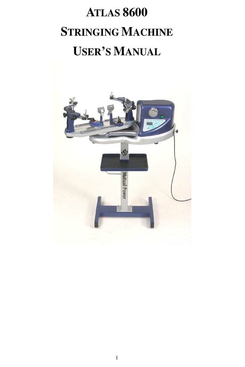
Gamma+ 9900 Els User manual

OWNER’S MANUAL
Issue 1 - June 2015
STRINGING MACHINE
9900 Els
2 PT SC MOUNTING

2
LIMITED WARRANTY
GAMMASPORTS warrants to the original purchaser that the 9900 Els stringing machine (“EQUIPMENT”) purchased is free
from defects in materials and workmanship for a period of five (5) years from the date of original purchase for mechanical
parts (excluding electrical parts and string clamps), and for a period of one (1) year from the date of purchase for all electrical
parts and string clamps. Should any defects develop under normal use within the specified time periods, GAMMA will at its
option, repair or replace the defective EQUIPMENT provided it is returned to GAMMAprepaid at the purchaser’s expense.
This warranty does not apply to any damage or defect caused by negligence, abuse, misuse, unauthorized alteration, ship-
ping, handling, or part wear and tear as a result of normal use.
Routine maintenance, adjustment, and cleaning required to ensure proper operation are the responsibility of the purchaser
and are not covered under the terms of this warranty. These include, but are not limited to: String Clamp adjustment, as
described on page 28, Clamp Base adjustment, as described on page 28, and the cleaning procedures listed on page 29.
GAMMA’sobligationunderthiswarrantyislimitedtorepairorreplacementofdefectiveEQUIPMENT,andnooneisauthorized
to promise any other liability. GAMMA shall in no event be liable for any incidental or consequential damages.
Toreturn defective EQUIPMENT,areturnauthorization(RA#)mustbeobtainedfromaGAMMAcustomerservicerepresenta-
tive. The RA# must be marked on the outside of the shipping carton being returned.All returns must be shipped prepaid by
the customer to GAMMA. Please retain the original shipping carton and packing materials for any future shipments. GAMMA
will not be responsible for machines which are not sent in the original undamaged packaging.
A GAMMA Care Service Plan is also available through GAMMA customer service, call 800.333.0337 for details.
TABLE OF CONTENTS
WARRANTY................................................................................................PAGE 2
FEATURES.................................................................................................PAGE 3
UNPACKING & ASSEMBLY INSTRUCTIONS............................................PAGE 4
POWER CONNECTION & CONTROLS.....................................................PAGE 11
CONTROL PANEL FUNCTIONS AND FEATURES....................................PAGE 12
DISPLAY SCREEN.....................................................................................PAGE 13
MACHINE FUNCTIONS..... ......................................................................PAGE 14
STRING GRIPPER OPERATION.............................................................PAGE 19
MOUNTING THE FRAME........................................................................ PAGE 20
STRINGING THE FRAME........................................................................PAGE 21
STRING LENGTH METER.......................................................................PAGE 25
ADDITIONAL FEATURES..........................................................................PAGE 26
PATHFINDER AWL....................................................................................PAGE 27
MAINTENANCE & ADJUSTMENTS.........................................................PAGE 28
TROUBLESHOOTING TIPS.....................................................................PAGE 30
PARTS LIST............................................................................................. PAGE 32
PARTS DRAWING....................................................................................PAGE 33
9900 Els
OWNER’S MANUAL
3
MACHINE FEATURES
Electric Constant Pull Tensioner with 11.0 to 90.0 lbs Tension
Range
Digital Tension Setting with LCD Display
Auto Start Quick Closing Linear String Gripper
Professional Two Point Self Centering Racquet Mounting
System- Accommodates All Racquets
Auto-Release Cam-Lock Swivel Base Clamps
4 Tooth Universal String Clamps
High Strength Extruded Aluminum Frame with Durable FRP
Finish and Convenient Deep Padded Tool Tray
Unique Turntable Clutch to Customize Rotation Friction
Convenient Foot Actuated Tensioner Switch
String Length Meter
MACHINE FEATURES

4
9900 Els
Unpacking Instructions & Contents
Instructions for Unpacking and Preparing for Assembly
The stringing machine is shipped in three cartons, a large master carton for the stringing
machine base with tensioner module and accessories, a medium carton for the turntable
and mounting system and a smaller carton for the floor stand post and base legs. Please
save the cartons and packing materials for possible shipments in the future. Gamma
Sports cannot be responsible for machines that are not returned, shipped in their original,
undamaged packaging. The tools you will need to assemble the machine are provided
with the machine. Due to the weight of the tensioner unit, you may need the assistance of
someone to help lift the tensioner unit out of the carton.
Once the cartons are opened, remove all inner cartons and check to be sure that all parts
are present and accounted for.
Contents of Electric Floor Stand (MMU3-20)
(1) Column Assembly
(4) Legs
(4) Leveling Feet
(4) M8 x 30 Flat Head Screws
(4) M8 x 35 Cap Screws
(4) M6 x 20 Cap Screws
(1) String Reel Holder (M8 Threaded Pin), (1) Knob, (8) Spacers, & (2) M8 Washers
Contents of Mounting System Carton (MMU3-28)
(1) Turntable Assembly w/ String Clamp Base and Mounting Stands w/ Frame Support
Slide, Side Supports, and Adapters
(2) String Clamps
(1) Package of spare plastic adapters for frame and mounting system supports
Contents of Machine Base Carton (MMU3-18)
(1) Stringer Assembly Unit w/ Tensioner Module
(1) Power Cord
(1) AC Adaptor
(1) Foot Pedal Tensioner Switch
(4) Rubber Feet for Table Top Use
(1) Wiring Harness for Electric Floor Stand Connection
(1) Stringing Tool Set - Includes 1 ea Diagonal Cutter, Bent Nose Pliers, Straight Nose
Pliers, Starting Clamp, Straight Awl & Pathfinder Specialty Awl
(1) Tools for assembly and maintenance

5
Floor Stand Leg Assembly
The stringing machine uses a four leg floor
stand design. The legs must be assembled
to the Lower Column before use. Remove
all parts from the shipping carton to confirm
that contents match the parts list.
Align the holes in the Leg Flange with the
matching holes in the Lower Column. Se-
cure the leg with one M8x30 flat head screw
through the upper hole, and one M8x35
socket head cap screw through the bottom
hole. Repeat this procedure for the three
remaining legs.
ASSEMBLY INSTRUCTIONS
Mounting the Floor Stand to the
Machine Base
The Floor Stand can be mounted to the ma-
chinebasebylayingthemachineonthefloor
to align the 4 holes in the flange plate to the
machinebaseorbysettingthemachineontop
of the upright Floor Stand. Note: If mounting
the machine base to the top of the upright
Floor Stand use the help of an assistant to
balance the machine base while aligning
and tightening the four cap bolts. Orient the
floor stand to the machine so that the boss
for the string reel will be on the left side of
the machine base and the floor stand power
switchisattherearsideofthemachinebase.
CAUTION: To prevent damage to the string gripper, never lift or
move the machine by the string gripper.

6
ASSEMBLY INSTRUCTIONS
Floor Stand Power Connection
PlugtheFloorStandpowercordfrombottom
left side of the tensioner housing into the
socket on the Floor Stand column.
Floor Stand Height Adjustment
The electric floor stand permits height adjust-
ments from 39” to 49”. The machine height
can be raised or lowered by depressing the
rocker switch Up or Down. When the desired
height is reached set the rocker switch to the
neutral position.

7
AC Power Adapter Storage Shelf
The AC Power Adapter Storage Shelf pro-
vides a means to secure and protect the
power adapter by storing it safely under the
machine base. This will reduce a potential
trippinghazardaswellaseliminatepotential
damage to the AC Power Supply if laying
on the floor.
AC Power Adapter Storage Shelf
TomounttheStorageShelf to the underside
of the base, align the holes in the storage
shelfbracket withthe holes inthe base. Use
a 6 mm hex wrench to tighten the two hex
head cap screws.
NOTE: Toavoidriskofdamagingthethreads
in the base, DO NOT OVERTIGHTEN.
AC Power Adapter Storage Shelf
PlacetheACPowerAdapterintotheStorage
Shelf. Coil the pin connector cable and tuck
it between the top of theAC Power Adapter
and the machine base.
ASSEMBLY INSTRUCTIONS

8
ASSEMBLY INSTRUCTIONS
String Reel Installation
The String Reel Holder pin is an 8 mm rod
with threads on both ends and flat surfaces
machinedononeend.Threadtheendofthe
pinwithouttheflatsurfacesintothethreaded
boss on the right side of the Lower Column.
Using the M6 open end wrench positioned
on the flat surfaces, securely tighten the pin
to the Lower Column.
TheStringReelHoldercanholdupto4reels
of string (depending on the size of the string
reel). Before placing the first reel on the rod,
slidetwospacersoverthepinandslidethem
to the connector on the Lower Column.
After the first reel is placed onto the rod, place two spacers between each reel to provide
enough space between reels to allow them to turn freely without rubbing against one another.
(To provide a smooth feed to the String Length Meter, place the reels on the rod so the string
spools off the reel from the underside of the reel).
After the last reel is installed, place the two M8 washers on the pin and attach the threaded
knob to the end of the rod.

9
ASSEMBLY INSTRUCTIONS
Turntable and Mounting System Installation
To install the Turntable position the Turntable over the turntable pin and align the holes in the
turntable with the holes in the turntable pin. Insert the bolts through the holes in the turntable
and turntable pin and tighten with an M6 hex wrench.
String Clamp Installation
The post of the String Clamp and tube of
the String Clamp Base may be treated with
grease to provide protection against corro-
sion during shipping and while in storage.
Remove any excessive grease with a clean
cloth prior to use. The post and tube may
also be cleaned with isopropyl alcohol.After
this type of thorough cleaning, the post and
tube should be treated with a light coating of
machine oil to protect the surfaces against
corrosion and to ensure smooth operation.
STRING CLAMP INSTALLATION

10
WARNING! FOR INDOOR USE ONLY.
NEVER OPEN UNIT WITH POWER CONNECTED.
CHILDREN SHOULD NEVER BE PERMITTED TO OPERATE THIS MACHINE
WITHOUT ADULT SUPERVISION.
Instructions for Power Connection and Controls
CAUTION ! Before connecting to the power supply, check the voltage source that the
machine is being connected to. The acceptable range of input voltages for this ma-
chine is between 100 V and 240 V @ 50 to 60 Hz. If you have any questions regarding
the input voltage supply for your area, please ask your electric utility company.
To install the power cord, insert the female end of the power cord into the AC Adapter and
then insert the female end of the cord from the AC Adapter into the A/C Power Cord Socket
“E” located on the back side below the tensioner. Plug the male end of the power cord into
a grounded power outlet. When using extension cords, use grounded heavy duty extension
cords rated for 15 AMP service.
Insert one end of floor stand power cord into the Floor Stand Power Socket “F” and the
other end into the power socket next to the rocker switch on the top column of the floor
stand.
Connect the Foot Pedal Switch by inserting the male pin at the end of the Foot Pedal
Switch cord into the Foot Pedal Switch Socket “G” located on the back panel of the Ten-
sioner.
Switch on the machine by pressing the On-Off Power Switch “D”.At start-up, the machine
will perform a self diagnostics check.
Back Panel Features
D - Power Switch
E - A/C Power Cord Socket
F - Foot Pedal Switch Socket
G - Floor Stand Power Socket
Front Panel Features
A - String Gripper
B - Tension Lever Switch
C - Control Panel with LCD Display
POWER CONNECTION & CONTROLS
C
B
A
D E G
F

11
CONTROL PANEL FEATURES

ESC Button - Press to return to the
Stringing Screen from the Settings
Screen, String Length Meter Screen or
to cancel a change being made to one
of the functional settings.
ENTER Button - Press to confirm and
save changes to any machine settings
and to zero the String Length Meter.
KNOT Button - Press once to enable
and display the Knot Icon - Press
again and hold while the Knot icon is
displayed to highlight the setting and
make changes.
RETURN Button - Press to return to
the Stringing Screen from the Settings
Screen, String Length Meter Screen or
to cancel a change being made to one
of the functional settings.
SOUND Button - Press to turn on or
turn off beeper. When in the Settings
Screen, the Sound Icon will include an
“X” when Beeper is disabled and “)))”
when the beeper is enabled.
MEMORY Button - Press to scroll
through 9 programmable Memory
Settings (M1-M9) - Press and hold for
5 seconds to enable Basic Stringing
Mode (M0).
PULLING SPEED Button - Press once
to display the Pulling Speed Icon - Press
again and hold while the Pulling Speed
Icon is displayed to highlight the setting
and make changes.
F1 Button - Press to display the Set-
tings Screen to view and make changes
to any of the machine settings. Pressing
and holding the F1 button for 5 seconds
will display the Information Screen,
which includes the total number of
strings pulled on the machine. Pressing
the ESC or RETURN button will exit
from the Information Screen.
MAIN/CROSS String Button - Press
to select and display the Main String
Tension Setting or the Cross String
Tension Setting. F5 Button - Press to reverse the order
in which the Memory Settings are
scrolled through - When the LED is illu-
minated the Memory Settings will scroll
in decreasing order.
PRE-STRETCH Button - Press once
to enable and display the Pre-stretch
Icon - Press again and hold while the
Pre-stretch Icon is displayed to highlight
the setting and make changes. F2-F3-F4 Buttons - Press to increase
String Tension values in the tens place
(F2), units place (F3) and tenths place
(F4) and press to increase setting val-
ues for Knot, Pre-stretch and Speed.
STRING LENGTH METER Button -
Press to enable and display the String
Length Meter - Pressing again will
toggle the measurement units between
feet (FT) and meters (M).
LBS/KG Button - Press to toggle the
Tension Setting between LBS and KG.
F6-F7-F8 Buttons - Press to decrease
String Tension values in the tens place
(F6), units place (F7) and tenths place
(F8) and press to decrease setting val-
ues for Knot, Pre-stretch and Speed.

12
DISPLAY SCREENS
Language Selection Screen
Atstart-up,ifalanguageotherthanEnglishis
desired,pressanyoneoftheF6-F8buttons
whentheStart-upScreenappearstochange
to the Language Selection Screen. Press-
ing any one of the F2-F8 buttons will scroll
throughthe available languages.Whenthe
desired language is highlighted, confirm by
pressing the Enter Button.
Self Diagnostic Test Screen
During start-up, the machine will automati-
cally perform a self-diagnostic test as the
gripper moves from left to right and back to
the left. The diagnostic checks will appear
on the display in the selected language.
Settings Screen
PressingtheF1buttonwillopentheSettings
Screen to view all current machine settings
on the same screen and to quickly make
changestoany of thesettings.If no buttons
are pressed within 10 seconds the Settings
Screen will revert to the Stringing Screen.
Stringing Screen
The Stringing Screen displays the tension
settings for the main strings and cross
strings. The large tension value on the
display and the highlighted Main String or
Cross String Icon will be the active tension
setting.Themachineonlypullstensionwhen
the Stringing Screen is displayed.

13
MACHINE FUNCTIONS
Setting Tension
To change the Tension Setting press F2
to increase the Tension Setting in the tens
place, F3 to increase the Tension Setting
in the units place and F4 to increase the
Tension Setting in the tenths place. To
decrease the Tension Setting press F6 to
decrease the Tension Setting in the tens
place, F7 to decrease the Tension Setting
in the units place and F8 to decrease the
Tension Setting in the tenths place.
NOTE: Continuing to press the buttons for the lower place values will increase or
decrease the higher place values.
Setting LBS-KGS
To select LBS (pounds) or KG (kilograms),
pressing the LBS-KG Button will toggle
back and forth between LBS and KG. The
tension setting can be switched between
LBS and KG at any time and the tension
setting will be displayed accordingly.
Setting Different Tensions for Main
Strings and Cross Strings
To preset Tension Settings for the Main
Stringsand CrossStrings, press theMAIN/
CROSS String Button to toggle between
the Main String and Cross String tension
settings.
TosetthetensionvaluefortheMainStrings,
press the MAIN/CROSS String Button and
when the Main String Icon on the display is highlighted, set the Main String tension value. To
set the tension value for the Cross Strings, press the MAIN/CROSS String Button and when
the Cross String Icon on the display is highlighted and set the Cross String tension value.
Once the desired Main String and Cross String tension values are entered, to save the set-
tings in the active Memory Setting press the ENTER button.
NOTE: The active tension setting is displayed by the large numbers on the screen for
whichever string icon is highlighted on the screen.

14
MACHINE FUNCTIONS
Permanent Memory Settings
There are 9 permanent Memory Settings
that can be used to store 9 combinations of
machine settings. Pressing the MEMORY
button will scroll through the 9 Memory
Settings in increasing order. To reverse the
scrollingorder,presstheF5button.TheBlue
LED will illuminate and the scrolling order
will be in decreasing order.
For any Memory Setting you can enter a specific Main String Tension, Cross String Tension,
Knot String Setting, Pre-stretch Setting and Pulling Speed Setting for a specific application,
such as type of string or set-up. Each setting can be entered and saved according to the
instructions on the previous and following pages.
Basic Stringing Mode
ABasicStringingModecanalsobeenabled
bypressing andholding the MemoryButton
for 5 seconds. When enabled the Blue LED
illuminates next to the Memory Button and
an M0 appears on the screen above the
Speed Icon.
TheM0BasicStringingModeisusedwhenyoudonotwishtouseoralteranyofthepermanent
Memory Settings that were pre-programmed and saved for specific applications. Settings are
not permanently saved when in the M0 Basic Stringing Mode. When the machine is turned
off all settings will revert back to the default settings when the machine is turned back on.
To change back to the Permanent Memory Setting Mode, press and hold the Memory But-
ton for 5 seconds until the Blue LED goes out and one of the 9 permanent Memory Settings
appears above the Speed Icon.

15
MACHINE FUNCTIONS
Setting the Pulling Speed from the
Stringing Screen
To change the Pulling Speed Setting while
in the Stringing Screen, first press the
PULLINGSPEEDbuttontodisplaythePull-
ing Speed Icon and Pulling Speed Setting
on the display. Then press and hold the
PULLING SPEED button again until the
Pulling Speed Setting is highlighted above
the Pulling Speed Icon. Press any of the F2, F3 or F4 buttons to increase the Pulling Speed
Setting in 10% increments and any of the F6, F7 or F8 buttons to decrease Pulling Speed
Setting in 10% increments. When the desired Pulling Speed Setting is displayed, press the
ENTER button to save the Pulling Speed Setting for the active Memory Setting.
NOTE: Selectable Pulling Speeds range from 30% (Slowest Pulling Speed) to 100%
(Fastest Pulling Speed) in 10% increments.
Setting the Pulling Speed from the
Settings Screen
TochangethePullingSpeedSettingfromthe
SettingsScreen,firstpressF1todisplaythe
Settings Screen. After the Settings Screen
appears on the display, press the PULLING
SPEEDbuttontohighlightthePullingSpeed
SettingabovethePullingSpeedIcon.Press
any of the F2, F3 or F4 buttons to increase
thePullingSpeedSettingin10%increments
andanyoftheF6,F7orF8buttonstodecreasePullingSpeedSettingin10%increments.After
the desired Pulling Speed Setting is entered press the ENTER button to accept and save the
Pulling Speed Setting for the active Memory Setting. If no other buttons are pressed within 10
seconds the display will return to the Stringing Screen. Pressing the ESC or RETURN button
will immediately return to the Stringing Screen.
NOTE: The slowest pulling speed should always be used when stringing very stiff
strings, such as aramid fiber strings. Stringing at slower pulling speeds will help to
reduce tension loss over time for any string types, especially for strings that tend to
lose tension more quickly than others.

16
MACHINE FUNCTIONS
Pre-stretch Function
The Pre-stretch function is used to pre-
stretch strings by increasing the applied
tensionbyasetpercentageoverthetension
setting before releasing the string and re-
pulling to the desired tension. This function
helps to reduce the amount of tension loss
in the strings over time.
Pressing the PRE-STRETCH button will
toggle the Pre-stretch function on and off and display the Pre-stretch Icon and Pre-Stretch
Setting. When the Pre-Stretch function is enabled, a small Pre-stretch Icon will appear on the
Stringing Screen below the Tens digit of the tension setting. When the Pre-stretch function
is disabled, or when the pre-stretch setting is 0%, the Pre-stretch Icon will not be visible on
the Stringing Screen.
Setting the Pre-Stretch from the
Stringing Screen
TochangethePre-stretchSettingwhileinthe
StringingScreen,pressthePRE-STRETCH
button once and while the Pre-Stretch Icon
is visible on the display, press and hold the
PRE-STRETCH button again until the Pre-
stretch Setting is highlighted. Press any of
the F2, F3 or F4 keys to increase the Pre-stretch Setting in 1% increments and any of the
F6, F7 or F8 keys to decrease the Pre-stretch Setting in 1% increments. When the desired
Pre-stretch Setting is displayed, press ENTER to save the Pre-stretch Setting for the active
Memory Setting.
NOTE: Selectable Pre-stretch Settings range from 0% to 30% in 1% increments.
Setting the Pre-stretch from the
Settings Screen
To change the Pre-stretch Setting from the
Settings Screen, press F1 to display the
Settings Screen. After the Settings Screen
appears on the display, press the PRE-
STRETCHbuttontohighlightthePre-stretch
SettingabovethePre-stretchIcon.Pressany
of the F2, F3 or F4 keys to increase the Pre-stretch Setting in 1% increments and any of the
F6, F7 or F8 keys to decrease the Pre-stretch Setting in 1% increments. When the desired
Pre-stretch Setting is displayed, press ENTER to accept and save the Pre-stretch Setting for
the active Memory Setting. If no other buttons are pressed within 10 seconds the display will
return to the Stringing Screen. Pressing the ESC or RETURN button will immediately return
to the Stringing Screen.

17
MACHINE FUNCTIONS
Knot String Function
TheKnot String functionisusedto increase
theappliedtensionbyasetpercentageover
the tension setting on the last main string
or cross string pulled before tying off. This
functionhelpstocompensatefortensionloss
causedbytheslackportionofthestringfrom
the string clamp to the tie-off knot.
Pressing the KNOT button will toggle the
Knot function on and off. When the Knot function is enabled, the Knot Icon will appear on the
Stringing Screen and the Blue LED will illuminate next to the KNOT button. The function will
be enabled for the next pull and then will automatically disable itself.
Setting the Knot Tension from the
Stringing Screen
To change the Knot Setting while in the
Stringing Screen, press the KNOT button
once and while the Knot Icon is visible on
the display, press and hold the Knot button
again until the Knot Setting is highlighted
above the Knot Icon. Press any of the F2,
F3 or F4 keys to increase the Knot Setting
in 1% increments and any of the F6, F7 or F8 keys to decrease the Knot Setting in 1% incre-
ments. When the desired Knot Setting is displayed, press ENTER to save the Knot Setting
for the active Memory Setting.
NOTE: Selectable Knot Settings range from 0% to 30% in 1% increments.
Setting the Knot Tension from the
Setting Screen
TochangetheKnotSettingfromtheSettings
Screen, press F1 to display the Settings
Screen. After the Settings Screen appears
on the display, press the KNOT button to
highlight the Knot Setting above the Knot
Icon. Press any of the F2, F3 or F4 keys to
increase the Knot Setting in 1% increments
and any of the F6, F7 or F8 keys to decrease the Knot Setting in 1% increments. When the
desired Knot Setting is displayed, press ENTER to accept and save the Knot Setting for the
active Memory Setting. If no other buttons are pressed within 10 seconds the display will
return to the Stringing Screen. Pressing the ESC or RETURN button will immediately return
to the Stringing Screen.

18
Auto-Start Quick Closing String Grip-
per Operation
The Quick Closing gripper will automatically
tension string without the need to press a ten-
sion lever or button. To tension a string, wrap
the string clockwise around the string guide
andinsertthestringbetweenthestringgripper
plates. Excessive slack in the string should
be removed before applying tension. Tension
stringbyplacingthestringbetweentheparallel
gripperjawsandpullingthestringperpendicular
tothe gripperplates.Asthegripperjawsbegin
moving forward they will engage the sensor
built into the front of the gripper housing and the gripper will automatically pull tension. To
release tension on the string depress the tension lever switch or use the foot pedal switch.
For adjustment of the parallel plates, see “Setting the Gripper Plate Spacing” on page 27.
STRING GRIPPER OPERATION
CAUTION: NEVER TENSION A STRING WITH YOUR FINGERS BETWEEN
THE STRING AND THE STRING GUIDE AS SERIOUS INJURY COULD RE-
SULT IF YOUR FINGER IS CAUGHT BETWEEN THE STRING AND STRING
GUIDE DURING TENSIONING. PUSH ANY BUTTON TO RELEASE
TENSION.

19
MOUNTING THE FRAME
Mounting Stand Adjustment
When mounting a racquet, adjust the
Mounting Stands so that the white Racquet
Supports on top of the Mounting Stands fit
inside the hoop of the racquet. Lower the
racquet over the Racquet Supports and
adjust the Mounting Stands until the sup-
ports just make contact with the inside sur-
face of the racquet at the head and throat.
There is an arrow on the face of each Ad-
justment Knob on the Turntable indicating
the turning direction that will “Tighten” the
mounting points by moving the 2pt Mount-
ing Stands further apart to bring the Racquet Supports closer to the inside surface of the
racquet at the head and throat. Turning the knobs in the opposite direction will move the
Mounting Stands closer together and will allow the Racquet Supports to move away from
the racquet frame.
Adjusting the Inner Racquet Supports
The white Racquet Supports are adjustable to accom-
modate all racquets and provide maximum support to
the racquet frame. Screw the pads up or down so they
contact the frame at a maximum height without blocking
the grommet holes.
Racquet Hold Down Clamp Operation
With the lever in the up position, insert the Racquet Hold
Down Clamp Pin into the hole in the center of the Mount-
ing Stand. Lower the Hold Down Clamp until it just makes
contact with the surface of the racquet. Using slight palm
pressure on the Hold Down Clamp depress the racquet
Hold Down Lever completely to secure the racquet frame
to the Mounting Stand.

20
MOUNTING THE FRAME
Special Throat Mounting
Racquets with a bridge that is thinner than
the rest of the frame or are tapered from
head to throat require special mounting
to ensure the frame is not damaged. The
white Support Pads need to be moved
from the inside of the racquet bridge to the
throat of the racquet.
Bridge
String Clamp Operation
The String Clamps are a dual action design
where the String Clamp and Clamp Base
operate independently of one another.
Toclampastring,lifttheStringClampandplace
the string between the jaws and depress the
String Clamp Lever to secure the string. The
clampingpressureappliedtothestringshould
be adjusted to provide sufficient pressure to
securethestringwhensubjectedtothedesired
pulling tension. The textured surface of the
teeth provide for increased friction between
theclamps and thestring toallowfor reduced
clamping pressure while securing and holding the string under tension.
Note that excessive pressure can damage both the strings and String Clamp.
Clamp Base Operation
TolocktheClampBasetotheTurntable,rotate
the Clamp Base locking lever clockwise until
it locks into place. Note that to lock the clamp
base lever, the string clamp must be lifted up
to disengage the release mechanism located
at the base of the tube.
ToreleasetheClampBasefromtheTurntable,
lowerthestring clamp into thetubetoengage
the release mechanism, or press the rocker
lever on the top of the clamp base lever.
To adjust the Clamp Base refer to page 23.
STRING CLAMP OPERATION
AUTO-RELEASE BASE OPERATION
Table of contents
Other Gamma+ Stringing Machine manuals

Gamma+
Gamma+ 6500 Els User manual

Gamma+
Gamma+ X-Stringer User manual

Gamma+
Gamma+ Progression 600 User manual

Gamma+
Gamma+ X-ST User manual

Gamma+
Gamma+ X-2 User manual

Gamma+
Gamma+ PROGRESSION 600ES-LED User manual

Gamma+
Gamma+ Progression ES II+ User manual

Gamma+
Gamma+ X-ST User manual

Gamma+
Gamma+ X-6 User manual

Gamma+
Gamma+ 5003 User manual

Gamma+
Gamma+ 6002 User manual

Gamma+
Gamma+ Progression STII User manual

Gamma+
Gamma+ PRO 100 User manual

Gamma+
Gamma+ Progression 602 FC User manual

Gamma+
Gamma+ 5800 Els User manual

Gamma+
Gamma+ 6900 Els User manual

Gamma+
Gamma+ 5003 User manual

Gamma+
Gamma+ Progression ES II User manual

Gamma+
Gamma+ X-6FC User manual

Gamma+
Gamma+ 6004 User manual