Gamma+ 7500 Els User manual


TABLE OF CONTENTS
LIMITED WARRANTY
GAMMA SPORTS ("GAMMA") warrants to the original purchaser that the GAMMA stringing machine ("EQUIPMENT") purchased is free from defects in
materialsandworkmanshipforaperiodoffive(5)yearsfromthedateoforiginalpurchaseformechanicalparts(excludingelectronicpartsandstringclamps),
and for a period of one (1) year from the date of purchase for electronic parts and string clamps. Should any defects develop under normal use within the
specified time periods, GAMMA will at its option, repair or replace the defective EQUIPMENT provided it is returned to GAMMA prepaid at the purchaser's
expense. This warranty does not apply to any damage or defect caused by negligence, abuse, misuse, unauthorized alteration, shipping, handling, or part
wear and tear as a result of normal use.
GAMMA's obligation under this warranty is limited to repair or replacement of defective EQUIPMENT, and no one is authorized to promise any other liability.
GAMMA shall in no event be liable for any incidental or consequential damages.
ToreturndefectiveEQUIPMENT, a return authorization(RA#)mustbe obtained from aGAMMAcustomerservice representative by calling1-800-333-0337.
TheRA#mustbemarked on theoutsideoftheshippingcarton being returned.Allreturnsmustbeshipped prepaid by thecustomertoGAMMA. Please retain
the original shipping carton and packing materials for any future shipments.
7500 Els
Owner’s Manual
INSIDE FRONT COVER .....................................................................WARRANTY
PAGE 1................................................................................................. FEATURES
PAGE 2................................................................ CONTENTS AND UNPACKING
PAGE 3.....................................................................ASSEMBLY INSTRUCTIONS
PAGE 9.................................................... POWER CONNECTIONS & CONTROL
PAGE 10................................ CONTROL PANEL FUNCTIONS AND FEATURES
PAGE 11.................................................STRING LENGTH METER OPERATION
PAGE 12........................................................... CAM-LOCK CLAMP OPERATION
PAGE 13.................................... STRING GRIPPER / TENSIONER OPERATION
PAGE 14.........................................................................MOUNTING THE FRAME
PAGE 15........................................................................ STRINGING THE FRAME
PAGE 16............................................................PATHFINDER AWL OPERATION
PAGE 17................................................... MAINTENANCE AND ADJUSTMENTS
PAGE 18............................................................................ CARE AND CLEANING
PAGE 19....................................................................TROUBLE SHOOTING TIPS
PAGE 20..............................................................PART NUMBERS AND LISTING

7500 Els
Key Product Features
1. Electric Constant Pull String Tensioner w/ Diamond Coated String Gripper
(10-90 lbs tension range in 0.10 lbs increments)
2. Electronic Control Panel w/ Keypad, Knot, Prestretch, & String Length Functions
3. String Reel Holder
4. Electronic String Length Meter
5. 6 Point “Suspension” Mounting System (10 point support)
6. Dual Action, CAM-Lock, Swivel, String Clamps w/ Diamond Coating
7. Convenient Foot Actuated Tensioner Switch
8. Full Fiberglass Cover w/ Integrated Tool Trays (76 sq in of storage area)
9. Height Adjustable from 39” to 46” (can also be used on table top)
10. 110 V / 220 V Compatibility
1
5 6 1
2
8
9
7
10
4
3

7500 Els
Unpacking Instructions & Contents
2
Instructions for Unpacking and Preparing for Assembly
The 7500 Els is shipped in two cartons, a large carton for the stringing machine and accessories and a smaller
carton for the post and base legs. Please save the cartons and packing materials for possible shipments in
the future. Gamma Sports cannot be responsible for machines that are not returned, shipped in their original,
undamaged packaging. The tools you will need to assemble the 7500 Els are provided with the machine. Due to
the weight of the tensioner unit, you may need the assistance of someone to help lift the tensioner unit out of the
carton.
Once the cartons are opened, remove all inner cartons and check to be sure that all parts are present and
accounted for.
Contents of Base & Leg Carton
(1) Lower Post
(2) Upper Post with Flange Plate
(4) Legs
(1) Locking Knob Screw
(4) M8 x 25 Flat Head Screws
(4) M8 x 30 Cap Screws
(1) String Reel Holder (M8 Threaded Pin), (1) Knob, (10) Spacers, & (2) M8 Washers
Contents of Large Master Carton (including accessory cartons packed inside)
(1) Stringer Assembly Unit w/ Tensioner Module and Turntable
(1) Power Cord w/ Ground Pin
(2) Suspension Mounting Stands w/ Frame Support Slide, Side Supports, and Adapters
(2) Mounting Stand Locking Levers w/ Washers
(2) String Clamp Heads
(2) Badminton Frame Support Slides Fitted w/ Plastic Adapter
(1) Package of Spare plastic adapters for mounting system supports (contains 12 pcs)
(1) Face Plate for String Length Meter & (4) Spare String Length Meter Clamp Pads
(4) Rubber Feet w/ Screws
(1) Foot Pedal Tensioner Switch
(1) Tool Kit (contains side cutter, bent nose pliers, needle nose pliers)
(1) Straight Stringers Awl & (1) Pathfinder Specialty Awl
(1) Starting Clamp
(2) Composite Badminton Floating Clamps
(1) 6 mm “T” Handle Hex Wrench
(1) 5 mm “T” Handle Hex Wrench
(1) 10 pc L-Hex Wrench Set
(2) Support Post Screws (M10)
(1) Box Wrench – 6 mm
3
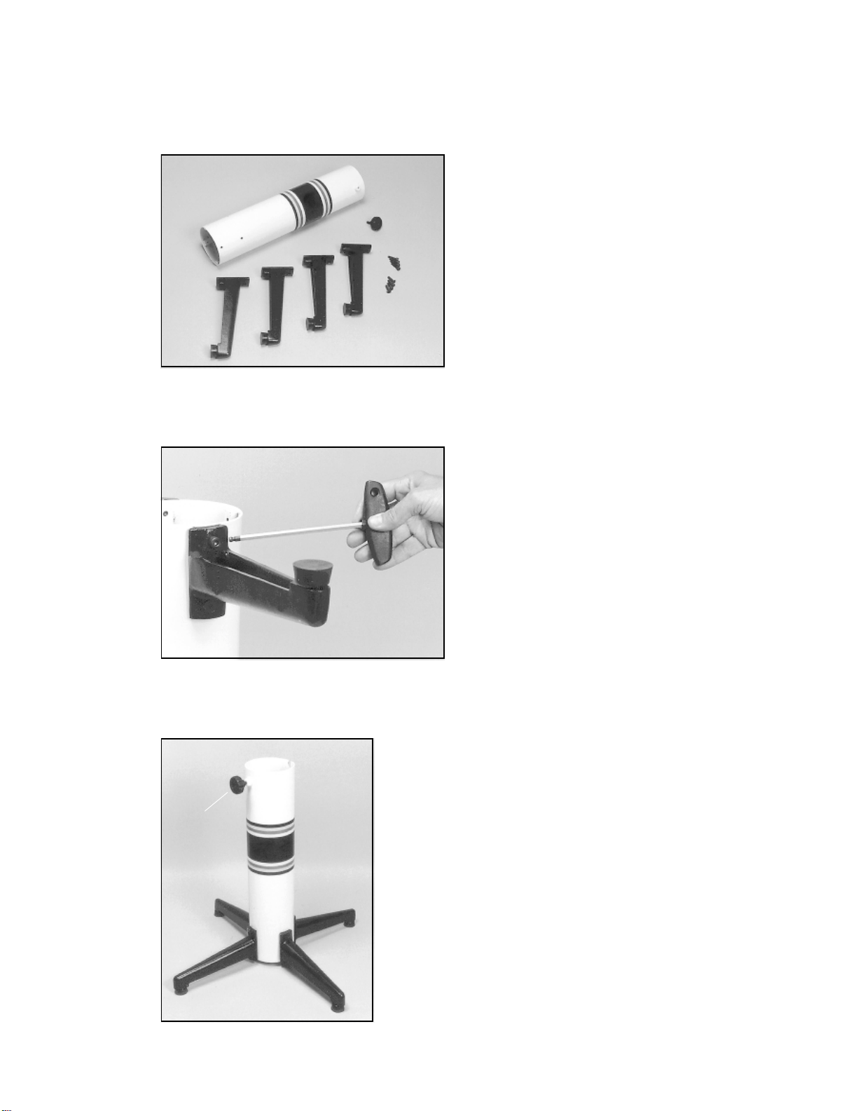
Base Leg Assembly
The stringing machine uses a four leg base design. The
legs must be assembled to the support post before use.
Remove the lower column support, the upper column
support, four (4) legs, four (4) socket head cap screws
andfour(4)flatheadcapscrews fromthesmallshipping
carton.
Base Leg Assembly (Cont.)
Align the holes in the leg flange with the matching holes
inthelowercolumnsupportpost.Securethelegwithone
FLAT HEAD cap screw through the upper hole, and one
SOCKET HEAD cap screw through the bottom hole.
Assembly Instructions
Base Leg Assembly (Cont.)
Tocomplete the basestand,screw the heightadjustmentlocking knob
(“A”) into the side of the support column. The locking knob should not
protrude beyond the inside of the support column at this time.
“A”

4
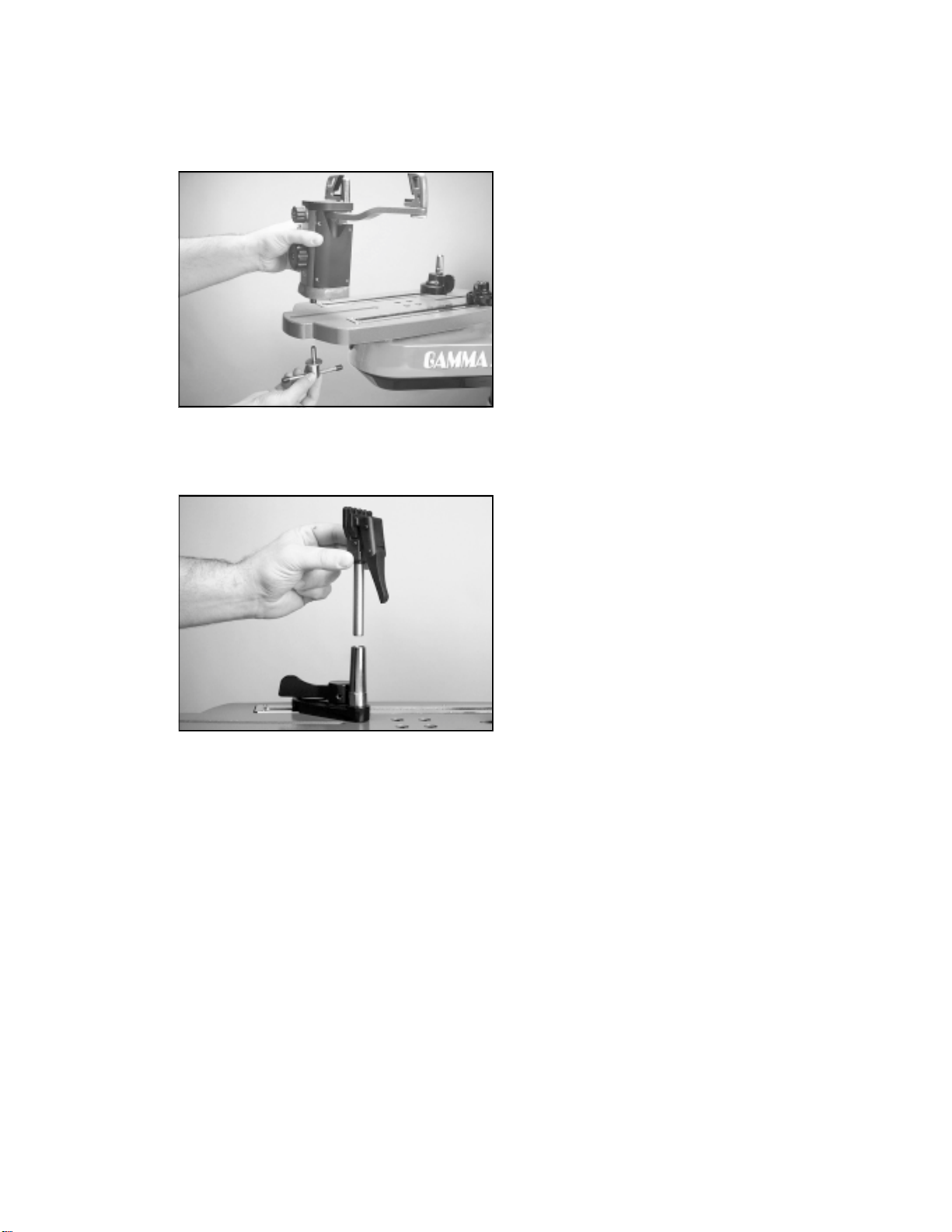
Foot Installation
CAUTION ! To maintain the alignment between the
fiberglass covers and the frame, it is very important
that the feet be installed before removing the four
center screws that attach the tensioner assembly to
the upper post flange.
To install the feet, tilt the tensioner back on its side and
screw the four feet into the holes at the corners of the
base.
Stand Upper Post Installation
After installing the four corner feet, remove the four (4)
button head cap screws from the base of the assembly.
Assembly Instructions
Unpacking the Tensioner Assembly
The tensioner assembly is packed inside the inner
cartonand is bolted to asheetof wood with four (4)bolts
to prevent damage during shipment. Another sheet of
wood is bolted to the underside of the inner carton
through the first piece of wood. First locate the nuts
attachedtotheboltsthatsecuretheouter pieceofwood
to the inner piece of wood. Remove the nuts and with
assistance carefully lift the tensioner assembly from the
innercarton and layit floor. Toremovethe innerpieceof
wood from the base of the machine, raise each end and
remove the four (4) shipping bolts from the underside of
thewoodensheet.Note:Pleaseretain thebolts,wood
and cartons for future shipment.

Assembly Instructions
Stand Upper Post Installation (cont.)
Withtheheight adjustment cap screw on theupperpost
facing the right side of the tensioner, align the four (4)
holes in the upper post flange with the holes in the
tensioner base. Secure the flange to the base with the
four cap screws.
Height Adjustment
The height of the machine is adjustable from 39” to 46”.
To change the height, remove the socket head cap
screw from its current position and place it in the
appropriate hole to set the desired height of the ma-
chine.
5
6
Clamp Head Installation
The post of the string clamp head and the tube of the
string clamp base are treated with grease to provide
protection against corrosion during shipping. Remove
anyexcessivegrease withaclean clothpriortouse.The
post and tube may also be cleaned with isopropyl
alcohol. After this type of thorough cleaning, the post
and tube should be treated with a light coating of
machineoiltoprotectthesurfacesagainstcorrosionand
to ensure smooth operation.
Installing the Racquet Mounting System
Align the threaded hole in the bottom of the frame
supportpostwiththeslotintheturntable.Screwthelever
lock bolt with washer into the center hole located in the
bottom of the support post and loosely tighten. Position
the washer with the rounded edge toward the turntable.
Repeat procedure for the support post on the opposite
side of the turntable.
There are two guide pins located in the bottom of the
support post. The outer guide pin may be removed if
needed to provide additional separation space between
themountingarmsformountingsuperoversizeracquets.
Assembly Instructions

String Reel Holder Installation
The string reel holder pin is an 8 mm rod with threads on
both ends, and flat surfaces machined on one end.
Threadtheendofthepinwithouttheflatsurfacesintothe
threaded boss on the right side of the lower column
support. Using the M6 open end wrench positioned on
the flat surfaces, securely tighten the pin to the lower
column support.
The string reel holder can hold up to 5 reels of string
(dependingonthe size of the string reel). Beforeplacing
thefirstreelonthepin,slidetwoM8washersoverthepin
and slide them to the boss on the lower column support.
After the first reel is placed onto the pin, place two
spacers between each reel to provide enough space
between reels and allow them to turn freely without
rubbing against one another. (To provide a smooth feed
to the String Length Meter, place the reels on the pin so
the string spools off the reel from the underside of the
reel.)
After the last reel is installed, place the remaining
spacer(s)onthepinandattach the threaded knob to the
end of the pin.
7

SLM Face Plate Installation
Remove the tape covering the opening on the front side
of the bottom cover to expose the string length meter.
Position the face plate assembly over the opening in the
bottomcover,andalignthetwocountersunk endholesof
the face plate with the threaded attachment holes in the
front of the string length meter. With the two flat head
machine screws, secure the face plate assembly to the
string length meter.
To check for proper alignment, lift the top clamp of the
face plate assembly and insert a section of racquet
stringatleast12incheslongintotheentranceholeofthe
face plate. Continue feeding the string section into the
stringlength meter,until itappearsthrough theexit hole.
Iftheentranceorexitholesappeartobeblocked,loosen
the attachment screws and adjust the position of the
face plate assembly until the section of string exits the
face plate. After the face plate is properly aligned,
tighten the flat head screws.
8
Table of contents
Other Gamma+ Stringing Machine manuals

Gamma+
Gamma+ PROGRESSION ST User manual

Gamma+
Gamma+ X-6 User manual

Gamma+
Gamma+ 6900 Els User manual

Gamma+
Gamma+ 6002 User manual

Gamma+
Gamma+ X-6FC User manual

Gamma+
Gamma+ 5800 Els User manual

Gamma+
Gamma+ Progression ES II+ User manual

Gamma+
Gamma+ Progression 602 FC User manual

Gamma+
Gamma+ X-Stringer User manual

Gamma+
Gamma+ 6500 Els User manual

Gamma+
Gamma+ 6004 User manual

Gamma+
Gamma+ 5003 User manual

Gamma+
Gamma+ X-ES User manual

Gamma+
Gamma+ X-6FC User manual

Gamma+
Gamma+ Progression Els User manual

Gamma+
Gamma+ PRO 100 User manual

Gamma+
Gamma+ 8800 Els User manual

Gamma+
Gamma+ 7900 Els User manual

Gamma+
Gamma+ 5002 User manual

Gamma+
Gamma+ 6004 User manual


