Gammill PLUS User manual

PLUS MACHINE MANUAL

Gammill Quilting Machine Company
1452 W. Gibson
West Plains MO 65775
(417) 256-5919 or (800) 659-8224
Fax: (417) 256-5757
Website: http://www.gammill.net
Copyright © 2004 by Gammill Quilting Machine Company
Reprinting or copying this manual either whole or in part is strictly prohibited without
written permission from Gammill Quilting Machine Company of West Plains, Missouri.

Plus™ Stitch Regulation
The Gammill Plus Control Center is
a custom designed, state of the art
stitch regulator system for quilting
machines. The system provides two
basic operational modes, Manual
(constant motor speed) and
Automatic (regulated stitch).
Some features of Plus Stitch
Regulation are:
•Sensors and alerts for top thread
break and/or low bobbin thread.
•Switch selectable ½ stitch and full
stitch operations are available in
either manual or automatic mode.
•Dual Liquid Crystal Display (LCD)
units to operate the sewing head
from either front or back.
•Dual channel locks (horizontal
and vertical) that can be enabled
or disabled while sewing.
•Needle position function to set
the needle to stop in the up or
down position.
•Safety feature in automatic mode
whereby the motor shuts off
automatically if the machine is
not moved within five seconds.
Controls
A Plus Control Center display unit is
located on both the front and back of
the machine. Each consists of a 4-
line LCD display, several push
button switches, and one toggle
switch on the left side. In addition to
the display unit, there are two
buttons on the ends of the machine
handles. The left handle has the
black Needle Position (NP) switch
and the right handle has the red
Run/Stop (RS) switch.
The buttons on the front of the
display unit include:
H Enables or disables the
Left/Right (horizontal) channel
lock
V Enables or disables the
Front/Back (vertical) channel
lock
A Selects automatic (stitch
regulation) mode
M Selects manual (constant
speed) mode
+ Increases stitches per inch or
motor speed
- Decreases stitches per inch or
motor speed
1

A toggle switch on the left side of the
display unit is for the needle
positioner. Use this switch to select
either the needle position (1/2 stitch)
function or the single stitch (full
stitch) function.
The right side handle switch is the
Run/Stop button. It enables or
disables automatic stitching mode or
turns the motor on or off in manual
mode.
The left side handle switch is the
Needle Position switch. The
function is determined by the setting
of the toggle switch on the side of
the display unit.
Indicators
Indicators are lights, sounds or
messages that indicate the system
status and include:
Alert
This is a red LED on the
upper middle portion of the
display unit. It is illuminated
when low bobbin or thread
breakage as been
detected.
Enabled
This is a green LED on the
middle upper portion of the
display unit. It is illuminated
when the stitch regulation
function is activated.
Beeper
An audible beeper is
sounded when first
entering stitch regulation
mode or when low bobbin
or thread breakage has
been detected.
Display
A four line, 20 character
LCD is provided to
communicate settings and
other information to the
operator.
Channel
Lock
LED
Below the (H) and (V)
buttons are red LED's
which are illuminated when
the channel lock magnets
are activated.
2

Stitch Regulation
(Automatic Mode)
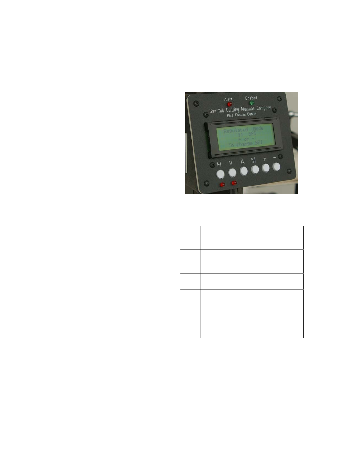
In this mode you will set the desired
stitches per inch. The stitching does
not start until you move the machine
head. While stitching in this mode
you may change the number of
stitches per inch. You cannot switch
from automatic mode to manual
mode while stitching in either mode.
1. Press Ato enter Automatic
mode. The word "Regulated" is
displayed on the control center.
2. Press the +(plus) or – (minus)
button to increase or decrease
the stitches per inch. You can
press these keys while stitching
as well to increase or decrease
the stitches per inch as you sew.
3. To begin sewing, press and
release the right handle switch.
Immediately after releasing the
switch, an audible beep sounds
and the green LED is illuminated
on the display unit. If the needle
is positioned down, the needle
will rise up out of the fabric. The
display unit will warn you that
automatic mode is enabled and
sewing head movement will
cause the sewing motor to run.
4. Move the sewing head to begin
sewing. While in automatic mode
you are free to speed up or slow
down movement of the sewing
head while still maintaining even
stitch length, however, rapid
speed changes should be
avoided. Moving the machine
rapidly or suddenly slowing the
machine after rapid movement
may result in a variation in stitch
length. Smooth machine
movement will result in better
quality stitching.
5. If you wish to increase or
decrease the stitch length as you
sew, simply press the +(plus) or
–(minus) button while continuing
to move the sewing head.
6. After sewing is complete, press
and release the run/stop switch.
If the needle positioner was
set in the down position
before you started stitching,
the needle will take a ½ stitch
and remain down in the fabric.
If the needle positioner was
set in the up position, it will
stop in the up position.
Constant Speed (Manual Mode)
In this mode you set the motor speed
then press the Run/Stop switch.
This starts the motor running at a
constant speed. You must
coordinate the movement of the
machine with the motor speed.To
enter Manual Mode, press the M
button. Set the motor speed by
pressing the +(plus) or –(minus) to
set the desired motor speed from 1
to 99% with +(plus) increasing the
speed and –(minus) decreasing the
speed. This speed can be adjusted
as you sew as well.
To begin sewing, press and release
the run/stop switch. The motor starts
running immediately after it is turned
on so you must be ready to
coordinate the movement of the
machine with start of the motor. Try
to maintain a smooth, even
movement of the sewing head which
3

gives you even stitch length. Slowing
down produces smaller stitches and
speeding up produces bigger
stitches.
To stop sewing press and release
the run/stop switch. Immediately
after releasing the switch the motor
stops. When the motor stops the
needle returns to the position in
which it was started.
Thread Break Detection
The Plus line of sewing heads
includes a thread break sensor
wheel. The top thread should be
wrapped around this sensor wheel
when threading the machine. In
either automatic or constant speed
mode, if the top thread breaks as
you are sewing, the sensor no longer
turns and a beeper sounds
continuously until the run/stop switch
is pressed. The words “Main Thread
Breakage Detected” are displayed
on the screen notifying you of a
thread break.
To stop the beeps, press and
release the run/stop switch. The
thread break sensor will continue
sensing a thread break during the
next sewing cycle. To disable the
thread break sensor, press the M
button on the display unit. Sensing is
then disabled until the machine is
turned off.
Low Bobbin Sensing
The bobbin thread is used up at the
same rate as the top thread. A
bobbin usage gauge is included in
the Plus line of quilting machines.
This estimation is based on the
bobbin being full and consistently
wound. To obtain the most accurate
bobbin usage you should clip the top
and bottom threads at the same
time. If the top thread is cut and the
bobbin thread is allowed to spool off
when the machine is moved, the
bobbin thread will run out before the
system alerts you it is low.
When the bobbin gauge determines
that the bobbin thread is low the low
bobbin alert beeps continuously until
the run/stop switch is pressed and
released.
To turn off the bobbin sensor press
the M button on the display. Bobbin
sensing will then be disabled until
the machine is turned off.
To Check Amount of
Bobbin Thread Remaining
Press and hold the Mbutton then
press and hold the A button.
Release the Mbutton and then
release the Abutton. The remaining
value of the bobbin thread is
displayed. If the value is low, you
may wish to insert a full bobbin
before continuing. You may wish to
have a full bobbin before stitching
the next row of an allover design to
avoid running out of bobbin in the
middle of the row.
If you change the bobbin you will
need to reset the bobbin counter by
pressing the +(plus) button. If you
do not change the bobbin press the
–(minus) button to exit the bobbin
counter without resetting it. The
bobbin counter should be reset each
time the bobbin is changed.
4

Needle Positioning
The needle position switch provides
needle position control. A toggle
switch on the side of the display unit
selects needle position or single
stitch mode. You may choose to take
½ stitches (needle position setting)
or full stitches (single stitch setting).
To Position the Needle Up or
Down
Flip the switch down to the Needle
Position setting. Press and release
the needle position switch. If the
needle was positioned up, it takes a
½ stitch down. If the needle was
positioned down, it takes a ½ stitch
up.
Each time you stop stitching, the
needle positions itself in this setting.
To change this position simply press
and release the left hand handle
switch. There are times when you
want the needle to remain in the
fabric when stitching is stopped to
prevent the needle from wobbling out
of the stitch path. These times might
include stitching in the ditch or using
templates or rulers.
To Take a Single Stitch
Flip the switch up to the Single
Stitch position.
Press and release the needle
position switch. The needle takes a
complete stitch returning to its
original position.
Slow Stitching
To take a series of slow stitches,
such as when securing threads,
press and hold the needle position
switch. If the toggle is set to Needle
Position a series of half stitches are
taken as the button is held down. If
the toggle is set to Single Stitch a
series of full stitches are taken as the
button is held down.
Troubleshooting Encoder
Problems
Checking Operation of Encoders
The proper operation of the
encoders and encoder cables can be
checked without operating the
machine:
1. To enter Diagnostic Mode do the
following:
a) Turn the power OFF.
b) Hold down the black, single
stitch button and turn the
power ON.
c) After a few seconds, release
the button.
2. The top line of the diagnostic
screen should read "encoder".
3. When either encoder wheel is
turned, the word "encoder"
should go from small letters to
capital letters. This indicates
proper operation of the encoder
circuit.
5

4. If the word "encoder" is missing
or does not change from small
letters to capital letters, then
further diagnostics is required.
5. If one encoder is working
properly and the other is not
working properly, then switch the
plugs at the back of the machine.
6. If the problem has switched to the
other encoder then the problem is
either the encoder cable or the
encoder. Most likely it would be
the encoder cable.
7. If the problem is still with the
"original" encoder then the
problem most likely resides in the
motherboard.
8. Exit diagnostic mode by turning
the power OFF then ON.
Regulated Stitch
Electrical Adjustments
After your Gammill Plus machine has
been used awhile there is a
possibility some of the electrical
values may need to be adjusted
slightly. Some indications that
adjustments are needed include:
•Needle over rotates.
•Stitch length is different than
setting indicates.
•Bobbin counter needs
adjustment.
•Needle Up/Down speed needs
adjustment.
To make these adjustments you
need to enter set-up mode. This is
done using the run/stop switch and
the control center from either side of
the machine. However, once you
enter set-up mode you need to make
all the adjustments from the same
side. While in set-up mode none of
the new adjustment values can be
tested. You will need to turn the
power OFF then ON to save and test
the new values.
To Enter Set-up Mode
1. If power is ON, turn it off. Press
and hold the run/stop switch
while turning on the power and
continue holding down the
run/stop switch for an additional
two seconds after the power is
turned on.
2. The display screen now shows
the first of 17 functions that can
be adjusted or selected.
Adjustments to the displayed
function are made by pressing +
(plus) or –(minus).
3. Press and quickly release
run/stop to advance to the next
function. You can only advance
to the next function and cannot
go back to a preceding function.
The last function, number 18,
exits set-up.
4. There is no need to cycle through
all 17 functions if you only want to
change a few of them. However,
in order to enter the new
adjustment values into the
system, you will need to advance
to the next function (press
run/stop). This can be compared
to hitting Enter on your computer.
6

Each function in set-up mode is
described below:
Needle Position Range
160 – 200
This number indicates the range of
speeds available when adjusting
Needle Up Speed (#2) and Needle
Down Speed (#3) below.
Needle Up Speed
6 - 10
Adjusts the speed at which the
needle rises up when the needle
positioner is used. Settings for this
function are very sensitive so
adjustments should be no more than
plus or minus 1. Additionally,
movement of the needle bar is
coordinated with that of the take-up
lever. If the setting is too high, the
needle and take-up lever will coast
past their proper stopping points.
The thread take-up lever should stop
at the corner of the casting in its
upward motion when machine is
automatically positioning the needle
upward. If the needle and/or take-up
lever are stopping past the proper
stopping point, press –(minus) once
to slow down the needle up speed.
Needle Down Speed
6 – 10
Adjusts the speed at which the
needle goes down when the needle
positioner is used.
Single Stitch Range
160 – 200
This number indicates the range of
speeds available when adjusting
Single Stitch Speed (#5) and Single
Stitch Time (#6) below.
Single Stitch Speed
6 - 10
Adjusts the speed the needle travels
while making a complete stitch when
in single stitch mode.
Single Stitch Time
Usually 110
Electrical value needed to allow
position sensor time to travel far
enough to lose the effect of the
position stop switch so machine can
complete a single stitch.
Time Out
Usually 02
When in Regulated Stitch Mode if
machine is no longer being moved
and if run switch is not turned off, the
machine will turn itself off
automatically after a few seconds.
Regulated Move Count
Always 01
Determines the sensitivity of
movement signal supplied to motor
with 1 being the most sensitive
setting.
Eight Stitches per Inch
Usually 27
Electrical value normally used to
achieve 8 stitches per inch. Note: 3
units = 1 stitch per inch. Example – if
you go from 27 to 33 you would get
10 stitches per inch.
Nine Stitches per Inch
Usually 30
Electrical value normally used to
achieve 9 stitches per inch.
Ten Stitches per Inch
Usually 33
Electrical value normally used to
achieve 10 stitches per inch.
7

Eleven Stitches per Inch
Usually 36
Electrical value normally used to
achieve 11 stitches per inch.
Twelve Stitches per Inch
Usually 39
Electrical value normally used to
achieve 12 stitches per inch.
Auto Break Delay
Usually 06
In automatic mode, when the thread
break sensor stops turning due to a
thread break, this function sets the
time delay before beeper and alert
light are activated.
Manual Break Delay
Usually 04
In manual mode, when the thread
break sensor stops turning due to a
thread break, this function sets the
time delay before beeper and alert
light are activated.
Bobbin Count Enabled
Yes or No
If No is chosen, the bobbin counter
is not active. If Yes is chosen, the
bobbin counter is active. The Bobbin
Multiplier (#16) below will need to be
set for the type of thread used.
Bobbin Multiplier
Usually 15
The top thread is wrapped around
the signal wheel. This causes the
signal wheel to rotate as the thread
is used. The number of revolutions of
the signal wheel determines when
the bobbin is running low. The
bobbin multiplier entered is multiplied
by 64 to determine when the low
bobbin alert is activated. We have
determined that 15 x 64 is the most
accurate setting when using average
thread. If coarse thread is used, you
should set the bobbin multiplier at 14
or 13. If fine thread is used you
should try 16 or 17.
Exit Screen --This screen tells you
that all new values are saved in
memory and to turn the power OFF
then ON to resume operations with
the new values.
Reset Bobbin Count
You can check the value of the
bobbin counter at any time. To
access the Bobbin Count Screen
Press Mthen A, release Mthen
release A. The number of counts left,
if any is displayed on the screen.
Each time the top thread rotates the
signal wheel; the computer lowers
the total count by one number
starting with the Bobbin Full Count
(BFC).
Example: 64-62-62-61…
When BFC reaches 0 the Bobbin
Full Multiplier (BFM) lowers by one
number.
Example: 15-14-13-12…
Each time the BFM drops a number
the BFC returns to 64 and starts
counting down again. When the BFM
count reaches 0 an audible alert is
sounded and the red light flashes to
alert you to check the bobbin thread
amount.
Example:
64-63-62…..3-2-1, 14,
64-63-62… 3-2-1, 13….
8

Each time a full bobbin is inserted in
the machine, the bobbin count
screen should be accessed and +
(plus) should be pressed to reset it
back to the full count. Failure to reset
bobbin count when full bobbin is
installed will result in false alarms.
Bobbin count screen can be
accessed at any time to check the
number of counts remaining even
though alerts have not been
activated. Run/Stop and Needle
Position switches will not operate
while bobbin count screen is open.
Touch –(minus) to exit screen and
return to normal operation.
Motor Run-Time Clock
To read the built-in Run-Time Clock,
press Mon the display panel while
turning on the power. Hold Mfor
approximately two seconds to allow
for run time clock to boot up. The
hours and minutes shown represent
the total time the motor on this
machine has run.
9
Table of contents
Other Gammill Sewing Machine manuals