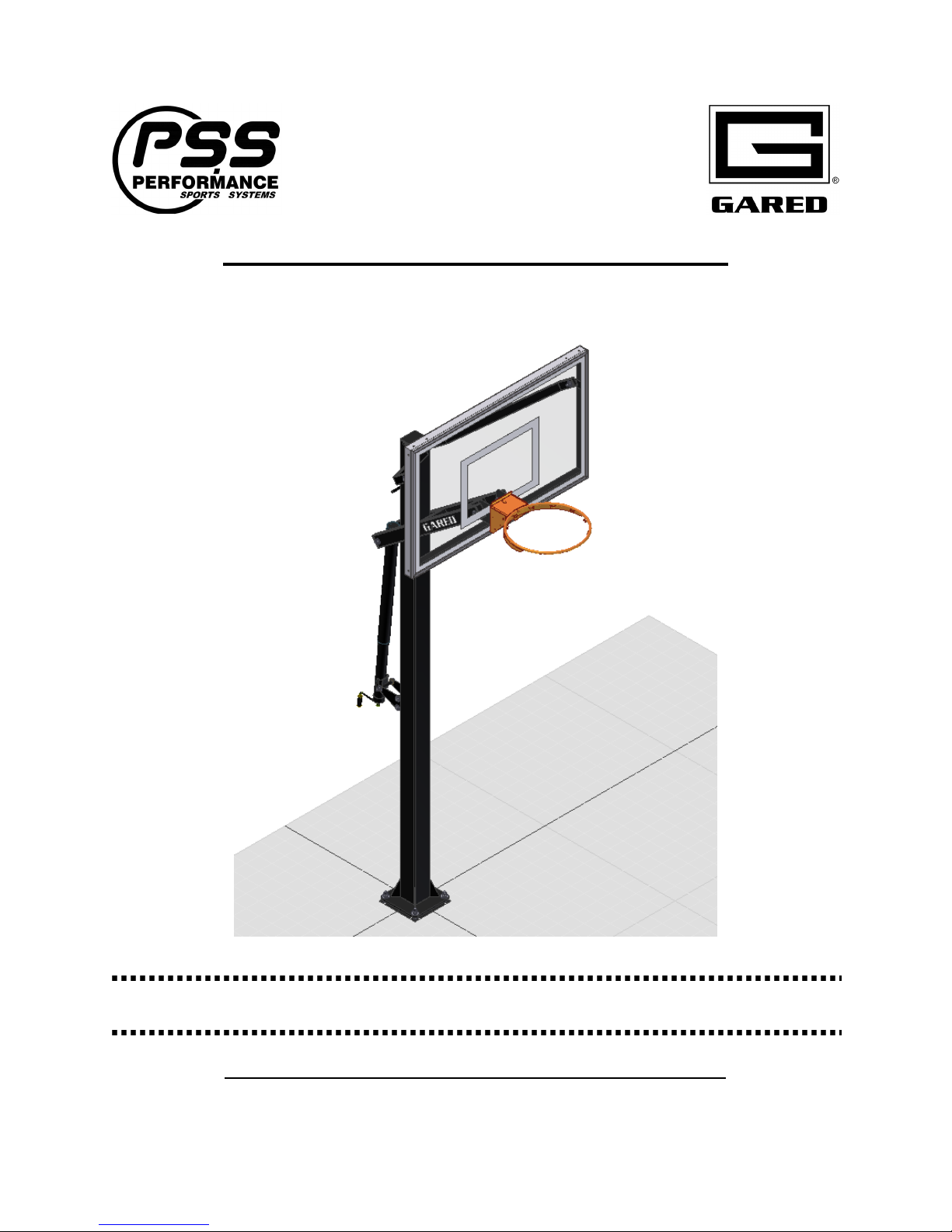
Varsity Jam Adjustable Basketball System
1
Table of Contents
Section Page No.
Introduction..........................................................................................................................1
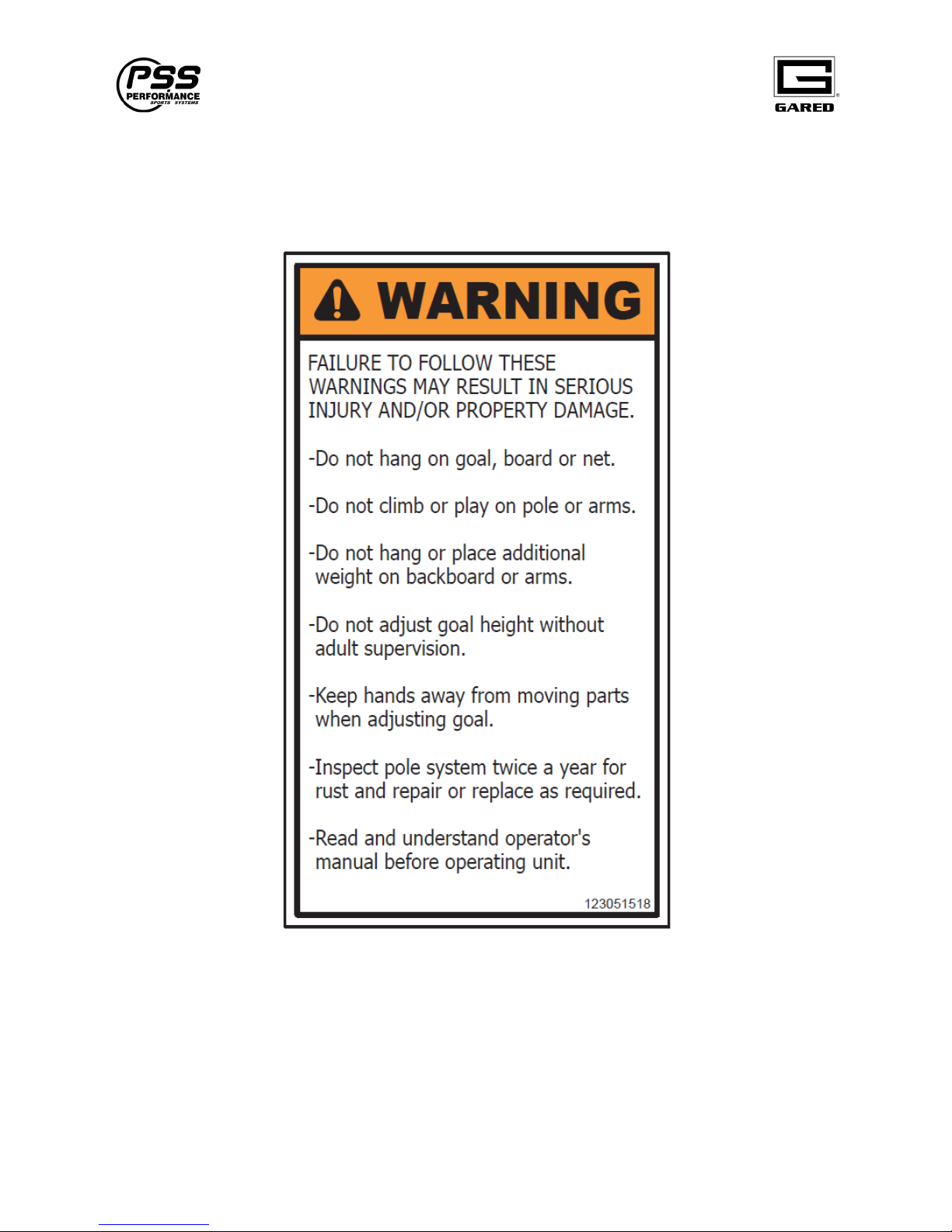
Safety ...................................................................................................................................2
Specifications.......................................................................................................................3
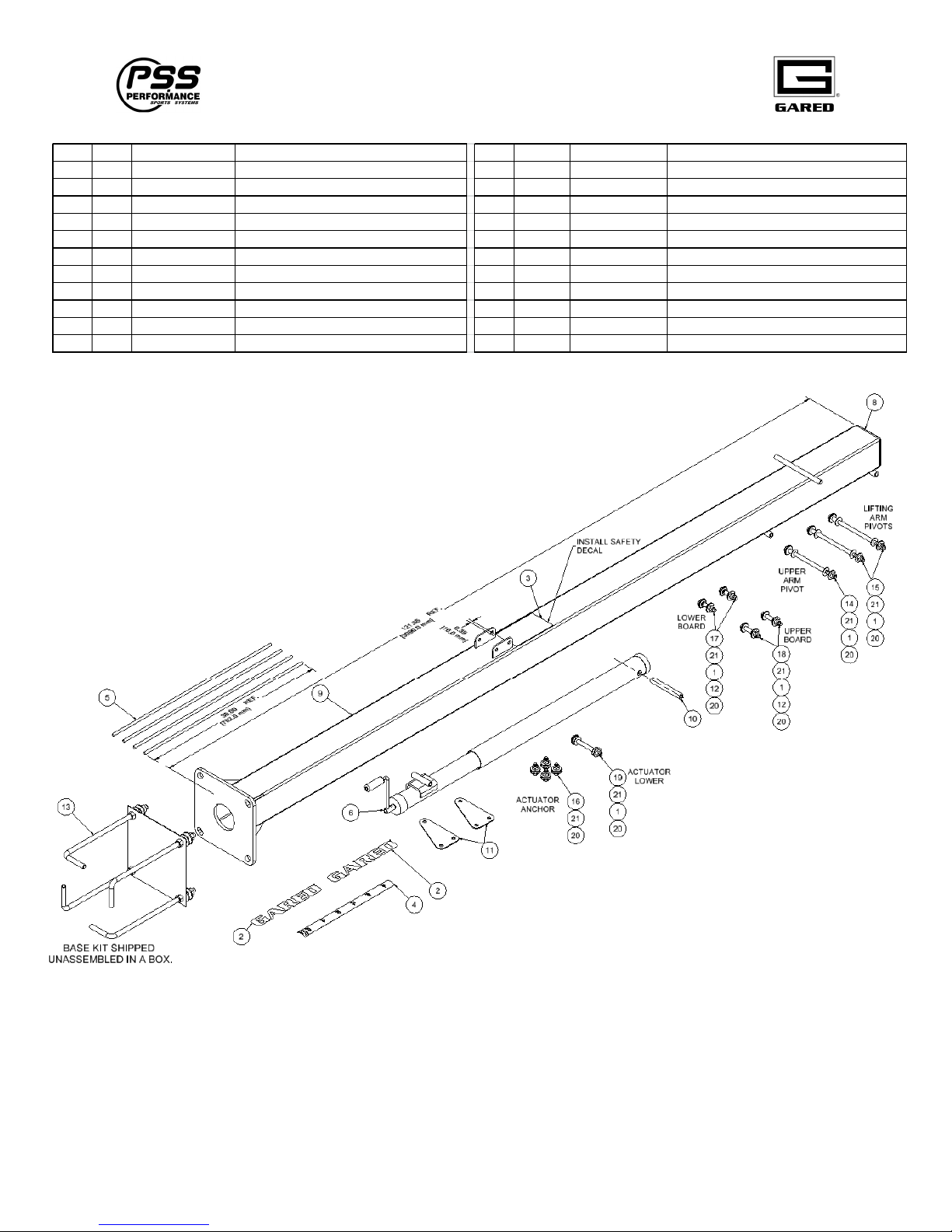
Parts Checklist ................................................................................................................. 4-5
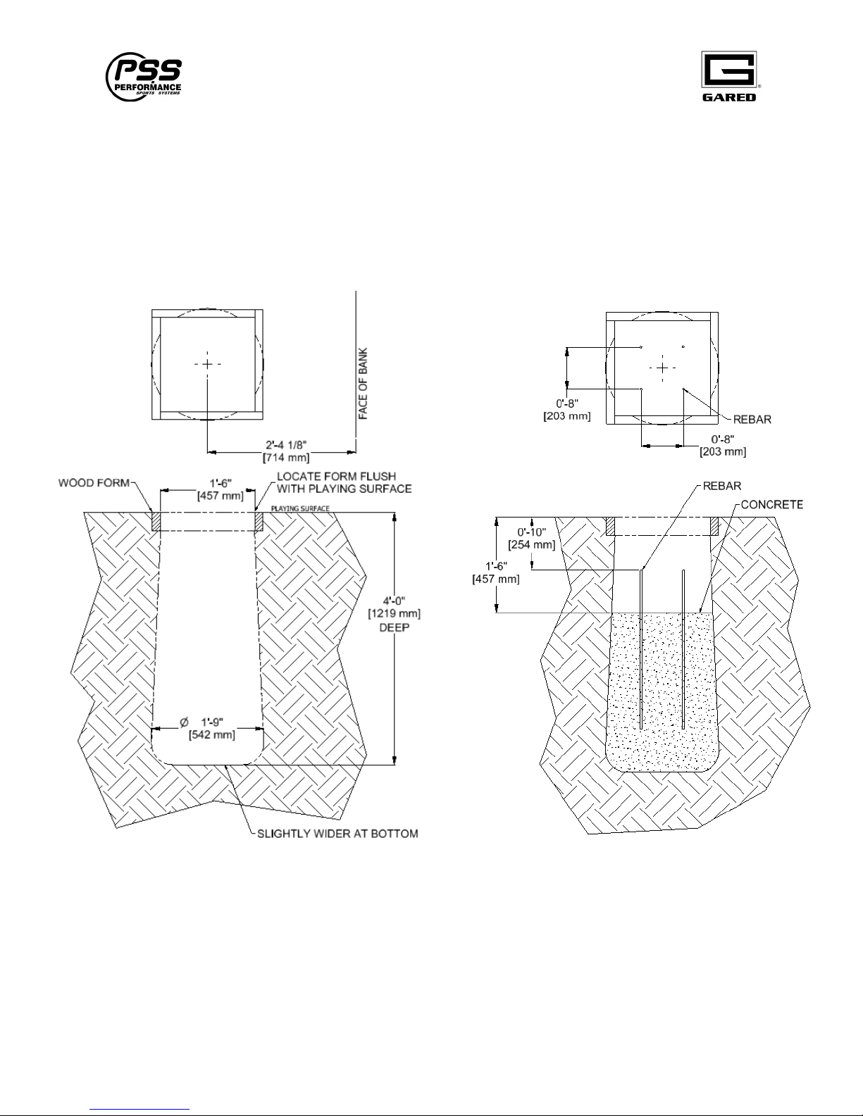
Installation...................................................................................................................... 6-17
Optional Post and Backboard Padding ........................................................................ 18-19
INTRODUCTION
Thank you for your purchase of a Gared Sports model Varsity Jam Adjustable Backstop. To
ensure that our equipment will provide years of use to you, we are including this installation,
operation, and maintenance guide. This guide will provide information on the proper assembly
and installation methods, operating procedures, and preventative maintenance of your portable
backstop.
Please note that a Bill of Materials is being included with this guide. Please check that all of the
parts called out on the Bill of Materials are present prior to beginning assembly and setup.
Please do not substitute for factory parts. Please contact your dealer or Gared or Performance
Sports Systems customer service department and allow them to determine if substitute parts are
acceptable.
It is recommended that an individual who has been properly trained perform assembly and set up
of the backstop. No one under the age of 18 should attempt assembly or set up of the unit, unless
properly supervised.
To prevent normal wear and tear from shortening the life of the unit, preventative maintenance
inspections and repairs should be performed at least once per year. If the units are subject to
high or unusual usage, inspections should be scheduled to occur more frequently. If items are
found to be nonconforming, replacements can be ordered from Gared, Performance Sports
Systems, or one of our authorized dealers. When contacting Gared or PSS, please have
information regarding the dealer/installer who sold the unit, the name of the project, and any
applicable warranty information.