Gared Pro-S Portable Backstop
4
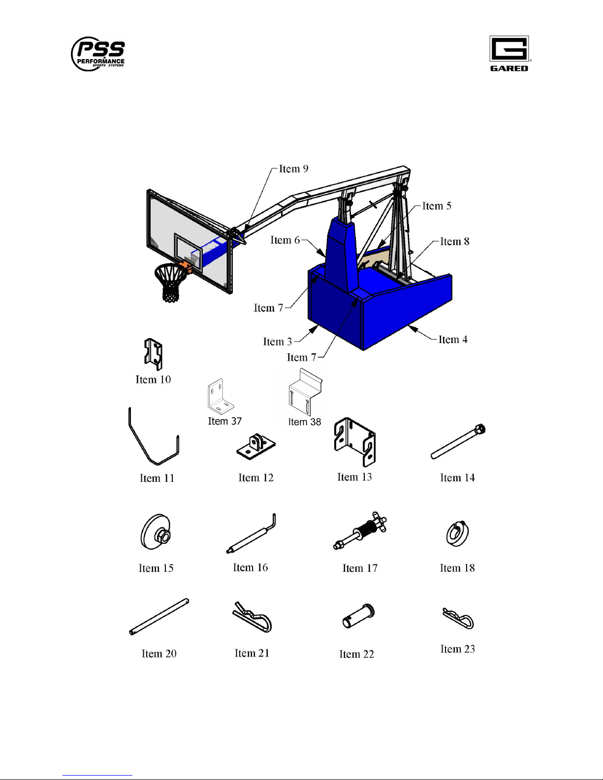
Parts Checklist
Verify all parts listed on packing list are present prior to installation. The following parts have
been packed separately. Because these units can use a variety of backboards and goals, the
specific part number is not referenced in the table. Please refer to your packing slip to verify the
correct board and goal has been received.
Item
Part Number Description Qty
1 Refer to Packing List Backboard 1
2 Refer to Packing List Goal 1
3 886555358 Front Base Pad 1
4 886555356 LH Base Pad 1
5 886555357 RH Base Pad 1
6 886555359 Upright Pad 1
7 886555360 Wheel Lift Pad 2
8 886555361 Center Unit Cover 1
9 886554049 Boom Pad 1
10 556453270 Backboard Brace Clamp 1
11 556453272 Backboard Brace 1
12 556453273 Backboard Brace Attachment Bracket 2
13 556453576 Quick Change Backboard Bracket 1
14 556554007 Stabilizer Screw 2
15 106553548 Leveling pad 2
16 556455329 Locator Pin 2
17 3005-15-05 Rear Anchor Tie Down Bolt 1
18 3509-15-00 1” Shaft Collar w/Set Screw 2
19 5025-08-00 ¾ OD x 5/8 ID Brass Flange Bushing 2
20 101653939 Quick Change Locking Rod 1
21 6380-11-00 Hitch Pin Clip 1/8” Diameter 2
22 111084108 Clevis Pin 3/8” x 1-1/8” 2
23 111094109 Hitch Pin Clip 3/32” Diameter 2
24 559054111 Ratchet Wrench ½” Square Drive 1
25 559054112 Socket 1-1/2” Six Point ½’ Square Drive 1
26 501-6-16-16 3/8-16 x 1” Carriage Bolt 4
27 501-6-16-36 3/8-16 x 2-1/4” Carriage Bolt 2
28 501-6-16-56 3/8-16 x 3-1/2” Carriage Bolt 2
29 502-6-16-16 3/8-16 x 1” Hex Head Bolt 4
30 548-6-16 3/8-16 Hex Whiz-Lock Nut 8
31 561-6 3/8” Flat Washer 4
32 562-6 3/8” Lock Washer 2
33 See Packing List Rear anchor Floor Insert 1
37 556554736 Bracket, Wheel Lift Pad Mount 4
38 556554095 Clip, Pad Attachment 2.0” 8
39 234-20-12Z Screw, Mach Pan HD Phil, ¼-20 x 3/4” 36
40 556554953 Striker Bolt, .67” Dia. 1
41 541-7-14 Hex Nut, 7/16-14 1
Contact Gared Customer Service at 800-325-2682 for assistance with replacement of any parts
missing or damaged.