Garland M1G1ACE User manual

Garland Technology
Modular Chassis
Available in 1U (4 Slots) and 2U (12 Slots)
AC or DC Power with Filtering Backplane
The M1GXXCE Filtering Backplane Chassis can receive up to 4 or 12 1Gbps Modules
depending on whether the chassis is a 1U chassis or a 2U chassis. Both chassis are equipped
with dual internal power supplies for either AC or DC power sources.
The backplane feature can be used with all the Garland Technology 1Gbps Modular TAPs. If
you have Garland Technology Modules purchased before this Aggregating Backplane Chassis
was released (April, 2015) and you want to be able to take advantage of the aggregating
backplane you will need to update the firmware of the modules. Otherwise, the modules will
operate as they normally would in the new chassis. There is a RJ-45 Management port that
allows access to the Command Line Interface (CLI) and a Ethernet RJ-45 Management port so
the Chassis can be connected to the network.
M1G2ACE/M1G2DCE
M1G1ACE/M1G1DCE
M1G2ACE/M1G2DCE
M1G1ACE/M1G1DCE
Row 1
Figure 1: M1GXXCE Row & Slot Layout
Page 1Page 1 VVeerr 11.6
Rear View
AC DC
Rear View
AC DC
Slot 4
Slot 3 Slot 4Slot 4
Slot 3
Slot 2Slot 2
Slot 2Slot 2
Slot 1Slot 1
Slot 1Slot 1
Slot 4Slot 4Slot 2Slot 2Slot 1Slot 1 Slot 3Slot 3 Slot 4Slot 2Slot 1 Slot 3
Row 1
Row 2
Row 3

Carefully unpack the chassis and install it into a 19" equipment rack. The model M1G1XCE will require 1U
of rack space and the model M1G2XCE will require 2U of rack space. You will need 2 AC or DC connections
to apply power to the two internal power supplies. Now insert your Garland Technology Modular TAPs by
carefully sliding into the available slots in the chassis.
If you are installing F series Modules, you will need to connect to the Chassis Management port to set up
the type of Filtering you require for your application.
If you are installing legacy modules you will be able to manage them through the management port as
you would in the standard Managed Chassis (for A series modules or BP series modules) or by setting up the
DIP switches located on the Module s logic board.
Connect a power cable to each of the M1GXXCE power supplies and plug them into an available power
source. Recommend plugging the cables into different power sources in case one should fail the other may
not.
Notes: 1. Fiber links are always 1000Mbps speed and Full Duplex.
2. Do not leave unused slots uncovered. Install a blanking plate on unused slots so that proper
internal air circulation is maintained.
To deploy the M1GXXCE Modular Chassis with Filtering Backplane into your network, the
following steps apply:
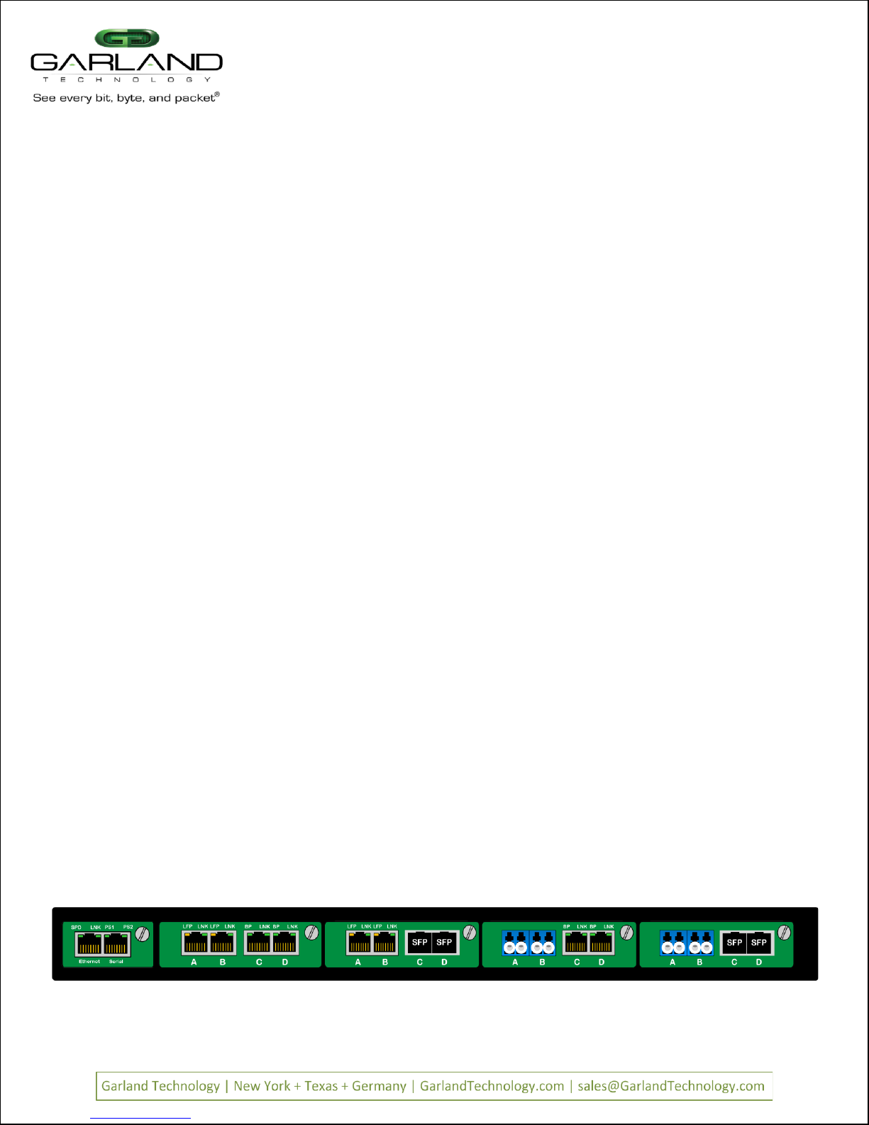
Figure 2: M1G1ACE with four TAP modules & a Management module
Page 2Page 2 VVeerr 11.6
Understanding the Filtering Backplane Chassis capabilities:
The M1GXXCE Filtering modular Chassis provides the user the capability of filtering network traffic at
Layers 2, 3 and 4 of a packet. Providing the monitoring tools with only the traffic that they are
interested in. This makes them more efficient to do the processing they are designed for.
Layer 2 filtering is filtering on source MAC address, destination MAC address or the VLAN ID. These
may be used in any combination with each other or any other filter field.
Layer3 filtering can target all IP messages or all non-IP messages. When IP is selected, the other layer
3 filter fields apear on the menu, these are source IP address, destination IP address, and DSCP.
These may be used in any combination with each other or any other filter as long as IP messaging has
been selected.
Layer 4 filtering can target TCP, UDP or any other layer 4 protocol. When TCP, or UDP is selected,
additional layer 4 menu items appear. These are source port and destination port. These fields are
only meaningful in TCP or UDP protocols.
M1G2ACE/M1G2DCE
M1G1ACE/M1G1DCE
M1G2ACE/M1G2DCE
M1G1ACE/M1G1DCE

Accessing the Garland Technology Modular Chassis with Filtering Backplane:
Connect to the RJ-45 Management port using the supplied cable. You will need a serial
terminal emulator like PuTTY using the settings listed below:
User Name: admin
User Password: gtadmin1
Bits per second: 115200
Data Bits: 8
Parity: None
Stop Bits: 1
Flow Control: None
Page 3Page 3 VVeerr 11..56
Main Menu
M1G2ACE/M1G2DCE
M1G1ACE/M1G1DCE
M1G2ACE/M1G2DCE
M1G1ACE/M1G1DCE
The Main Menu provides access to the five main areas that can be controlled on the M1GXXCE chassis.
Option 1 gives you access to configuring the individual modules.
Option 2 provides access to set up Filtering of each module to the backplane
Option 3 provides the capability to manage the Username and Password for the chassis.
Option 4 provides the capability to manage the Network configuration
Option 5 provides the capability to upgrade the soft
Option 0 allows you to Log Out
Figure 3: Main Menu
Garland Technology M1G1ACE (Code Version: 1.0.21)
Main Menu
Select:
1. Change/View Module Configuration
2. Filtering
3. Change Username/Password
4. Settings
5. Upgrade
0. Logout
Once you login the above screen will be presented. This is where you will set up the chassis
so that you can manage it through the Ethernet Network Management port.
Press on the Main Menu to open the Settings menu.
Garland Technology M1G1ACE (Code Version: 1.0.21)
Settings Menu
1. NetworkConfig
2. Key Press Timeout
0. Exit
Select:
Figure 4: Settings Menu
Press to get to the Network Configuration Menu

Page 4Page 4 VVeerr 11..6
M1G2ACE/M1G2DCE
M1G1ACE/M1G1DCE
M1G2ACE/M1G2DCE
M1G1ACE/M1G1DCE
Figure 5: Here is where the static ip address can be changed so you can log into the network via the Ethernet port
Garland Technology M1G1ACE (Code Version 1.0.21)
Network Configuration
Warning: This session depends on the current network config.
Applying network config may drop this session.
link: up
current ip add:10.10.10.200
current config:static add: 10.10.10.200 mask:255.255.255.0 gwy:10.10.10.1
new config:static add: 10.10.10.200 mask:255.255.255.0 gwy:10.10.10.1
1.re-init interface
3.ip address
4.netmask
5.gateway
0.exit with new config
ctrl-c.exit with NO new config
select:
Setting up Network Configuration
Unless your network IP address is 10.10.10.200 you will need to change the default IP address. In order to do this you
will need to connect to the serial management port so you can set up the Network parameters. Using the furnished
RS232 to DB9 cable;
1. Connect the RJ45 end to the RJ45 Serial Port on the M1GXXCE chassis.
2. Connect the other side of the RS232 cable to your PCs RS232 port.
3. Use any terminal emulation software (PuTTY, HyperTerminal, Etc.) to connect to the CLI interface in order to
manage the M1GXXCE chassis.
4. Set the following terminal communication parameters:
Speed: 115200-default
Data Bits: 8
Parity: none
Stop Bits: 1
Flow Control: No flow control
5. Power on the M1GXXCE chassis
6. The Login prompt will appear in the terminal window
7. Enter the default Login name (admin)
8. Enter the default password (gtadmin1)
9. After login you should change user name and password. If you plan to use management Ethernet port, set IP address, net mask
and gateway parameters. The default IP address is 10.10.10.200 and the Network mask is 255.255.0.0 and the Gateway 0.0.0.0.
Remember to save your changes.
Garland Technology M1G1ACE (Code Version: 1.0.21)
Key press timeout Menu
Current timeout: 60 minutes.
Enter a value between 1-60 (minutes):
Pressing on the settings Menu will present the following menu. This menu lets you determine how long
the session will stay active following the last keystroke.
Note: Only one login is allowed at a time.
Figure 6: Key press timeout Menu

Page 5Page 5 VVeerr 11..6
M1G2ACE/M1G2DCE
M1G1ACE/M1G1DCE
M1G2ACE/M1G2DCE
M1G1ACE/M1G1DCE
Garland Technology M1G1ACE (code Version: 1.0.21)
Upgrade Menu
1. Upgrade using download file version 1.0.21
0. Exit
Select:
The ability to download upgrades to the M1GXXCE Chassis through the network is a great feature. There is
no need to have to send the chassis back to the factory to be upgraded. You simply request the upgrade file
from Tech Support place it on you desktop and set up the chassis Uploader to do the rest of the job. Press
to Exit back to the Main Menu. Once back to the Main Menu, press again to log out of the
Management System. We do not want to do that yet, what we will do next is set up the Filters.
Pressing will bring you back to the Main MenuNext, we will go to the Upgrade Menu
by pressing
Garland Technology M1G1ACE (Code Version: 1.0.21)
Main Menu
Select:
1. Change/View Module Configuration
2. Filtering
3. Change Username/Password
4. Settings
5. Upgrade
0. Logout
Before being able to upgrade the Chassis with the latest software, the user needs to place the file onto the
desktop. The Uploader address for this product is IP address of the Chassis. So go to your preferred Browser
and enter the IP address and a simple screen will appear. Press the Choose File button and find the upgrade
file that you placed on your desktop then press the Upload Button. The Uploader will upload the upgrade
file to the chassis. After the web interface has transferred the file to the chassis, the user must go to the
upgrade menu on the CLI (Press 5 on the Main Menu). There, he will see option 1 appear IF the uploaded
file uploaded intact and is recognized as an upgrade file for this product. Verify that the uploaded version is
the version that you expected. Once you press option 1 the program will then install the upgrade and reboot
the system. Task accomplished.
Figure 7: Main Menu
Figure 8: Upgrade Menu

This screen provides the chassis Serial Number and the condition of the power supplies as to whether they
are UPor DOWN
It also displays the Model Number of the Modules inserted in the chassis if a module is present.
Pressing number 1 through 4 will select the slot of the module you want to manage.
Figure 9: Change/View Module Configuration
Page 6Page 6 VVeerr 11..6
Selecting on the Main Menu will bring up the Select Slot Number Screen.
Select slot number to view/modify
Chassis Serial Number: 21870000107 Controller Serial Number: 21910000112
Power Supply 1: Down
Power Supply 2: Up
#: Module Type
Operating Mode (Current State)
----------------------------------------------------------------------------
1: M1GCCBP 2: M1GCCF 3: M1GCCF 4: M1GCCF
Bypass (Bypass)
Press
1: Select Slot 1 2: Select Slot 2 3: Select Slot 3 4: Select Slot 4
0. Exit
Figure 10: Show Status of the Module of the selected Slot 1
Selecting Slot brings up the Slot 1 Status Screen
=========================
Slot 1 Status:
=========================
Current Bypass State: Bypass
Port A Port B Port C Port D
Link State: Down Down Down Down
Duplex: Auto Auto Auto Auto
Media Type: RJ45 RJ45 RJ45 RJ45
Serial Number: 2076-0020461
=========================
Slot 1 Select Option:
=========================
Press
1: Set Operating Mode (Bypass)
2:Set Speed(1G)
3:Set LFP Mode (ON)
4: Set Duplex Mode
5: Set Reverse Bypass Mode (OFF)
6: Set Forced Bypass Mode (OFF)
b: Restore Defaults
Press Enter to refresh this status screen
0. Exit
M1G2ACE/M1G2DCE
M1G1ACE/M1G1DCE
M1G2ACE/M1G2DCE
M1G1ACE/M1G1DCE

Page 7Page 7 VVeerr 11..6
Figure 11: Show Status of the Module of the selected Slot 2
Selecting Slot brings up the Slot 2 Status Screen
=========================
Slot 2 Status:
=========================
Port A Port B Port C Port D
Link State: Down Down Down Down
Speed:
Duplex:
Media Type: RJ45 RJ45 RJ45 RJ45
Serial Number: 00000
Software Version: Boot:1.2.2 App:1.2.45
=========================
Slot 2 Select Option:
=========================
Press
2:Set Speed(Synchronize)
b: Restore Defaults
Press Enter to refresh this status screen
0. Exit
The TAP Module in slot 2 is different than the module in slot 1. This screen is to show that the slot number
screens may be slightly different depending on the functionality of the TAP modules inserted in the slot.
Pressing when on the Slot 1 Status Screen, will bring up this screen.
Figure 12: Select the TAP mode of the TAP in this slot
=========================
Slot 1 TAP Mode Configuration
=========================
Current Mode: Bypass
New Duplex: Bypass
1. Breakout
2. Aggregate
3. Span
4. Bypass
0. Return and Apply
M1G2ACE/M1G2DCE
M1G1ACE/M1G1DCE
M1G2ACE/M1G2DCE
M1G1ACE/M1G1DCE

Figure 13: Show Speed setting of the selected module
Page 8Page 8 VVeerr 11..6
Pressing when on the Slot 1 Status Screen of a Copper TAP Module,
will bring up this screen.
=========================
Slot 1 Speed Mode Configuration
=========================
Current Speed: 1G
New Speed: 1G
1. 1G
2. 100M
0. Return and Apply
Figure 14: This screen lets you control LFP ON or OFF
Pressing when on the Slot 1 Status Screen of a Copper TAP Module, will bring
up this screen.
====================
Slot 1 LFP Configuration
====================
Current LFP state: ON
New LFP state: ON
1. ON
2. OFF
0. Return and Apply
LFP is used mostly for HA designed networks. When turned on, it can sense a network failure
and reflect the failure to the adjacent port of the live network allowing the networks failover
mechanism to switch over to the secondary network path.
M1G2ACE/M1G2DCE
M1G1ACE/M1G1DCE
M1G2ACE/M1G2DCE
M1G1ACE/M1G1DCE

Page 9Page 9 VVeerr 11..6
Pressing when on the Slot 1 Status Screen of a Copper TAP Module, will bring
up the Duplex Configuration Screen.
=========================
Slot 1 Duplex Configuration
=========================
Current Mode:
Link: Port A Port B Port C Port D
New Duplex: Auto Auto Auto Auto
Current Duplex: Full Full Auto Auto
1. Auto
2. Full Duplex
0. Return and Apply
Figure 15: Setting up Duplex Mode
This screen will let you set the Duplex mode if the Speed setting is less that 1Gbps.
If the Speed is 1Gbps, the Duplex mode is forced to Autonegotiate.
Pressing when on the Slot Status Screen of a Copper Bypass TAP Module, will
bring up the Reverse Bypass Mode Configuration. Reverse Bypass disables link on
both live network ports if any inline appliances lose link or cannot pass traffic. This
feature is disabled by default.
Figure 16: Setting up Reverse Bypass Mode ON or OFF
==========================
Slot 1 Reverse Bypass Mode Configuration
==========================
Current Reverse Bypass: OFF
New Reverse Bypass: OFF
1. ON
2. OFF
0. Return and Apply
M1G2ACE/M1G2DCE
M1G1ACE/M1G1DCE
M1G2ACE/M1G2DCE
M1G1ACE/M1G1DCE

Pressing b when on the Slot Status Screen of a Copper TAP Module, will bring
up this Restore Defaults screen.
Pressing #2 on the Main Menu Screen, will begin the Filtering setup process.
We will set up filters for Layer 2, Layer 3 and Layer 4;
Filtering
Figure 19: Restore Defaults
Garland Technology M1G1ACE (code Version: 1.0.21)
Select Row
1: M1GCCBP M1GCCF M1GCCF M1GCCF
0: Back
The Select RowScreen
Below is the screen you get when pressing '2' on the main menu. This is a 2U chassis, so this
menu allows you to select one of three rows to set up filters. Pressing on a 1U chassis
would take you directly to the Filter Row menu.
Page 10Page 10 VVeerr 11..6
We will show the setting up of some Layer 2, 3 and 4 filters in the following screen shots.
Pressing when on the Slot Status Screen of a Bypass Copper TAP Module, will
bring up this Restore Defaults screen.
==========================
Slot 1 Forced Bypass Configuration
==========================
Current Forced Bypass: OFF
New Forced Bypass: OFF
1. ON
2. OFF
0. Return and Apply
Figure 18: Restore Defaults
==========================
Slot 4 Restore Defaults
==========================
1: Restore defaults
0: Exit without restore
Figure 18: Restore Defaults
==========================
Slot 4 Restore Defaults
==========================
1: Restore defaults
0: Exit without restore
Figure 17: Restore Defaults
M1G2ACE/M1G2DCE
M1G1ACE/M1G1DCE
M1G2ACE/M1G2DCE
M1G1ACE/M1G1DCE

Page 11Page 11 VVeerr 11..6
Layer 2 Filtering
Layer 2 filtering allows filtering on source MAC address, destination MAC address or the VLAN ID.
These may be used in any combination with each other or any other filter field.
Garland Technology M1G1ACE (Code Version:1.0.21)
Row 1 Filters
No Filters Defined for row 1.
u:cursor up d:cursor down t:filter up g:filter down
a:add e:edit i:insert x:delete
v:view c:clear count r:reset h:help
0:exit
Select:
Garland Technology M1G1ACE (Code Version: 1.0.21)
Select Ingress Port(s)
map: [unav| i | |i ]
Slot 2 M1GCCF:
3: A2 [ ]
4: B2 [*]
Slot 3 M1GCCF:
5: A3 [ ]
6: B3 [ ]
Slot 4 M1GCCF:
7: A4 [*]
8: B4 [ ]
e: Egress Ports Menu
0: Exit
We now have an iin the B2 and A4 positions of the ports
map line and an oin the D4 position of the ports map line.
Press to return to the Row 1 FiltersScreen
Figure 26: Case 432A w/Ingress & Egress
Press Returnand the filter name case 432Agets
placed on the Name Line of the Edit Filter Menu.
Press so we can select the ingress port (s) for this
filter.
Pressing takes you directly to the Select Ingress
Port (s)menu. Press and This places an asterisk
in the Brackets of port B2 and port A4 as well as placing
is in their respective positions on the ports map. You
can go directly to the Select Egress Port (s) menu to
setup the egress port (s) by pressing e
Press eto bring up the Select Egress Port (s) screen then
press 8 to place an asterisk in D4 brackets and an oin the
appropriate place on the ports map. Then press to
return to the Edit Filter Menu.
Figure 23: Edit Filter Menu Figure 24: Ingress Ports Menu
Figure 25: Select Egress Port (s) Menu
Press ato begin the process of adding and defining a filter.
Figure 20: Row Filters Menu
Row Filters Menu
The Filter has a name The Select Ingress PortsMenu
Egress PortsMenu Ingress/Egress ports for filter Case 432A
Edit Filter:
1. Name : case 432A
2. Ports : [ | | | ]
3. Counter Used : YES
4. Source MAC Address :
5. Destination MAC Address:
6. VLAN ID :
7. Layer 3 :
0: Exit
Enter menu selection:
Garland Technology M1G1ACE (Code Version: 1.0.21)
Select Egress Port(s)
map: [unav| i | |i o]
Slot 2 M1GCCF:
3: C2 [ ]
4: D2 [ ]
Slot 3 M1GCCF:
5: C3 [ ]
6: D3 [ ]
Slot 4 M1GCCF:
7: C4 [ ]
8: D4 [*]
i: Ingress Ports Menu
0: Exit
Edit Filter:
1. Name : case 432A
2. Ports : [unav| i | |i o]
3. Counter Used : YES
4. Source MAC Address :
5. Destination MAC Address:
6. VLAN ID :
7. Layer 3 :
0: Exit
Enter menu selection:
The Filter Nameline appears below the menu. First
delete the word FILTER then enter the new filter name
'case 432A'
Figure 22: Filter Name Edit
Naming the Filter
Edit Filter:
All Values in Decimal.
1. Name : Filter
2. Ports : [ | | | ]
3. Counter Used : YES
4. Source MAC Address :
5. Destination MAC Address:
6. VLAN ID :
7. Layer 3 :
0: Exit
Enter menu selection:
Filter Name: Case 432A
Edit Filter:
1. Name : Filter
2. Ports : [ | | | ]
3. Counter Used : YES
4. Source MAC Address :
5. Destination MAC Address:
6. VLAN ID :
7. Layer 3 :
0: Exit
Enter menu selection:
This is the Edit Filter Menu. The program provided
the default name 'Filter'. Press '1' to change the
filter name.
Figure 21: Edit Filter Menu
Edit FilterMenu
M1G2ACE/M1G2DCE
M1G1ACE/M1G1DCE
M1G2ACE/M1G2DCE
M1G1ACE/M1G1DCE

Page 12Page 12 VVeerr 11..6
We now have a filter case 432Awhich can send traffic from ports
B2 and A4 to port D4 (slot 2 port B and slot 4port A to slot 4 port
D). At this point ALL traffic will be sent as no filters havebeen
defined. Note the presence of the Sin the menu. This indicates
that the filter has not been saved in flash memory or downloaded to
the modules yet.
Press Snow
Figure 27: Row 1 FiltersScreen showing the case 432A filter
Return to the Row 1 FiltersScreen
Garland Technology M1G1ACE (Code Version:1.0.21)
Row 1 Filters ***FILTER CONFIGURATION NOT SAVED OR APPLIED***
#: Name Ports Count
-> 1: Case 432A [unav| i | |i o] 0
u:cursor up d:cursor down t:filter up g:filter down
a:add e:edit i:insert x:delete
v:view c:clear count r:reset h:help
0:exit *** s:SAVE AND APPLY FILTERS ***
Select:
Edit Filter:
1. Name : case 432A dmac
2. Ports : [unav| i | |i o]
3. Counter Used : YES
4. Source MAC Address :
5. Destination MAC Address:
6. VLAN ID :
7. Layer 3 :
0: Exit
Enter menu selection:
Back to the Edit Filter Screen
Figure 31: Edit Filter Menu to set Destination MAC
Press so we can provide a name for the new filter. In this case we
will add to the existing name case 432Awe will enter dmac at the
end of the current name. Press 5 to setup Destination MAC.
Note: The name of the filter is for Users convenience only and does no affect the operation.
So multiple filters with the same name are allowed.
Edit Filter:
1. Name : case 432A dmac
2. Ports : [unav| i | |i o]
3. Counter Used : YES
4. Source MAC Address :
5. Destination MAC Address:
6. VLAN ID :
7. Layer 3 :
0: Exit
Enter menu selection:
filter on DESTINATION MAC address? [N]:
The program will add filter on DESTINATION MAC address? [N]:line
at the bottom of the menu. Press yto add the address.
Figure 32: Begin setting up the destination MAC address
Pressing adds a line to the menu
Figure 30: Edit Filter Menu to set Source IP
Row 1 Filters Screen after pressing F1
Garland Technology M1G1ACE (Code Version:1.0.21)
Row 1 Filters ***FILTER CONFIGURATION NOT SAVED OR APPLIED***
#: Name Ports Count
-> 1: Case 432A [unav| i | |i o] 0
1: Case 432A [unav| i | |i o] 0
u:cursor up d:cursor down t:filter up g:filter down
a:add e:edit i:insert x:delete
v:view c:clear count r:reset h:help
0:exit *** s:SAVE AND APPLY FILTERS ***
Select:
Now we can edit the new filter we just added by pressing E
The program is saving the filter to Flash and downloading to the
modules.
Figure 28: Row 1 Filters screen while saving the filter
The Filter is now being saved
Garland Technology M1G1ACE (Code Version:1.0.21)
Row 1 Filters ***FILTER CONFIGURATION NOT SAVED OR APPLIED***
#: Name Ports Count
-> 1: Case 432A [unav| i | |i o] 0
u:cursor up d:cursor down t:filter up g:filter down
a:add e:edit i:insert x:delete
v:view c:clear count r:reset h:help
0:exit *** s:SAVE AND APPLY FILTERS ***
Select:
Updating filters in modules in row 1, slot 1, 2, 3, 4 ...
Garland Technology M1G1ACE (Code Version:1.0.21)
Row 1 Filters
#: Name Ports Count
-> 1: Case 432A [unav| i | |i o] 0
u:cursor up d:cursor down t:filter up g:filter down
a:add e:edit i:insert x:delete
v:view c:clear count r:reset h:help
0:exit
Select:
Row Filters Sceen after saving filter 432A
Figure 29: Edit Filter Menu to set Destination MAC
Notice the SSave and Download selection is gone. Now we want to
copy the filter then edit it to filter on the destination MAC address.
Pressing function key F1to copy the currently selected filter.
M1G2ACE/M1G2DCE
M1G1ACE/M1G1DCE
M1G2ACE/M1G2DCE
M1G1ACE/M1G1DCE

Page 13Page 13 VVeerr 11..6
Edit Filter:
1. Name : case 432A dmac
2. Ports : [unav| i | |i o]
3. Counter Used : YES
4. Source MAC Address :
5. Destination MAC Address:
6. VLAN ID :
7. Layer 3 :
0: Exit
Enter menu selection:
filter on DESTINATION MAC address? [N]:y
Enter DESTINATION MAC address? (hex): c8:20:f
We will enter 'c', '8','2','0','f'. If any other digit besides 0-9 and a-f is entered
such as a ga warning message will appear. For example pressing gwill warn
of an INVALID CHARACTER.
Begin Adding DESTINATION MAC address
Figure 34: Entering the destination MAC address
Pressing gcaused - !INVALID CHARACTER! Message to Pop up. Thegis
not entered on the line.
Edit Filter:
1. Name : case 432A dmac
2. Ports : [unav| i | |i o]
3. Counter Used : YES
4. Source MAC Address :
5. Destination MAC Address:
6. VLAN ID :
7. Layer 3 :
0: Exit
Enter menu selection:5
filter on DESTINATION MAC address? [N]:y
Enter DESTINATION MAC address? (hex): c8:20:f
If an invalid character is entered
Figure 35: Enter the next octet of the Source IP Figure 36: Enter remainder of address
Enter the remainder of the DESTINATION MAC address - a
and if you entered the numbers correctly, the program will
announce that you have entered a valid MAC addressPress enterto
accept the MAC address.
Enter the remainder of the address
Edit Filter:
1. Name : case 432A dmac
2. Ports : [unav| i | |i o]
3. Counter Used : YES
4. Source MAC Address :
5. Destination MAC Address:
6. VLAN ID :
7. Layer 3 :
0: Exit
Enter menu selection:5
filter on DESTINATION MAC address? [N]:y
valid MAC address Enter DESTINATION MAC address? (hex): c8:20:f1:57:3a:42
Figure 37: The Destination MAC address is added to line 5
Please note that entering the SOURCE MAC address is operationally the same as
entering the DESTINATION MAC address. If a SOURCE MAC address is entered at
this point, the filter would require a packet to match both criteria before passing
that packet. Press to return to the Row 1 Filter screen.
We now have a valid Destination MAC address
Edit Filter:
1. Name : case 432A dmac
2. Ports : [unav| i | |i o]
3. Counter Used : YES
4. Source MAC Address :
5. Destination MAC Address: c8:20:f1:57:3a:42
6. VLAN ID :
7. Layer 3 :
0: Exit
Enter menu selection:5
Figure 38: the Case 432A dmac has been created
Press Sto savethe filters to flash and download to the modules
Back to the Row 1 Filters Screen
Garland Technology M1G1ACE (Code Version:1.0.21)
Row 1 Filters ***FILTER CONFIGURATION NOT SAVED OR APPLIED***
#: Name Ports Count
-> 1: Case 432A dmac [unav| i | |i o] 0
1: Case 432A [unav| i | |I o] 0
u:cursor up d:cursor down t:filter up g:filter down
a:add e:edit i:insert x:delete
v:view c:clear count r:reset h:help
0:exit *** s:SAVE AND APPLY FILTERS ***
Select:
Edit Filter:
1. Name : case 432A dmac
2. Ports : [unav| i | |i o]
3. Counter Used : YES
4. Source MAC Address :
5. Destination MAC Address:
6. VLAN ID :
7. Layer 3 :
0: Exit
Enter menu selection:
filter on DESTINATION MAC address? [N]:
Enter DESTINATION MAC address? (hex):
The program will add Enter DESTINATION MAC address? (hex):
line at the bottom of the menu. Press yto add the address. at
this point, the controller expects the user to enter 6 hex numbers.
The':' delimiting colons are added automatically for
convenience. Hex numbers expected are two digits each with
digitsbeing 0-9 or a-f.
Press yto add MAC address
Figure 33: ready to enter destination MAC address
M1G2ACE/M1G2DCE
M1G1ACE/M1G1DCE
M1G2ACE/M1G2DCE
M1G1ACE/M1G1DCE

Page 14Page 14 VVeerr 11..6
Garland Technology M1G1ACE (Code Version:1.0.21)
Row 1 Filters ***FILTER CONFIGURATION NOT SAVED OR APPLIED***
#: Name Ports Count
1: Case 432A dmac [unav| i | |i o] 0
2: Case 432A [unav| i | |i o] 0
-> 3: abc [unav|i | o | ] 0
u:cursor up d:cursor down t:filter up g:filter down
a:add e:edit i:insert x:delete
v:view c:clear count r:reset h:help
0:exit *** s:SAVE AND APPLY FILTERS ***
Select:
Back to the Row 1 Filters Screen
Move the selection cursor up by pressing the <up arrow>. Since filters 1 and 2
both use the same ingresses, packets coming in will try to meet the criteria for
filter case 432 dmac and will only go to other filters if there is no match. To
change the order (priority) of a filter, use Tto move the filter up one row or G
to move it down one row.
Figure 44: provide VLAN ID
Edit Filter:
1. Name : abc
2. Ports : [unav|i | o | ]
3. Counter Used : YES
4. Source MAC Address :
5. Destination MAC Address:
6. VLAN ID :
7. Layer 3 :
0: Exit
Enter menu selection:
filter on VLAN ID? [N]:y
Enter VLAN ID(decimal):768
Enter 768 for the VLAN ID
Enter for the VLAN ID then press <enter>
Figure 42: provide VLAN ID
Edit Filter:
1. Name : abc
2. Ports : [unav|i | o | ]
3. Counter Used : YES
4. Source MAC Address :
5. Destination MAC Address:
6. VLAN ID : 768
7. Layer 3 :
0: Exit
Enter menu selection:
VLAN ID defined
Press to return to the Row 1 Filters Screen
Figure 43: vlan 768 assigned
Figure 40: Add a new filter
We will create the new filters name
Adding a new filter named abc
Edit Filter:
1. Name : FILTER
2. Ports : [ | | | ]
3. Counter Used : YES
4. Source MAC Address :
5. Destination MAC Address:
6. VLAN ID :
7. Layer 3 :
0: Exit
Enter menu selection:
Figure 40: Add a new filter
We will create the new filters name
Adding a new filter named abc
Edit Filter:
1. Name : FILTER
2. Ports : [ | | | ]
3. Counter Used : YES
4. Source MAC Address :
5. Destination MAC Address:
6. VLAN ID :
7. Layer 3 :
0: Exit
Enter menu selection:
Edit Filter:
1. Name : abc
2. Ports : [unav|i | o | ]
3. Counter Used : YES
4. Source MAC Address :
5. Destination MAC Address:
6. VLAN ID :
7. Layer 3 :
0: Exit
Enter menu selection:6
Set up filter name and port mapping
Figure 41: Enter Name and port mapping
Change the filter name to abcand set up port mapping as was previously
described - Port A on slot 2 and port C on slot 3.
Press to enter the VLAN ID. Then pressy
Figure 39: We now have two Filters on the Row 1 Filters Screen
The S:Save and downloadselection has been removed.
We now want to create a new filter called abcThis filter will look for packets
with a VLAN ID 768 from port A on slot 2 and send themto port C on slot 3. So
we will press ato add the filter
The Filter is saved
Garland Technology M1G1ACE (Code Version:1.0.21)
Row 1 Filters
#: Name Ports Count
-> 1: Case 432A dmac [unav| i | |i o] 0
1: Case 432A [unav| i | |i o] 0
u:cursor up d:cursor down t:filter up g:filter down
a:add e:edit i:insert x:delete
v:view c:clear count r:reset h:help
0:exit
Select:
M1G2ACE/M1G2DCE
M1G1ACE/M1G1DCE
M1G2ACE/M1G2DCE
M1G1ACE/M1G1DCE

Layer 3 filtering can target all IP messages or all
non-IP messages. When IP is selected, the other
layer 3 filter fields appear on the menu, these are
source IP address, destination IP address, and
DSCP. These may be used in any combination with
each other or any other filter as long as IP
messaging has been selected.
Layer 3 filtering
Page 15Page 15 VVeerr 11..6
Garland Technology M1G1ACE (Code Version:1.0.21)
Row 1 Filters ***FILTER CONFIGURATION NOT SAVED OR APPLIED***
#: Name Ports Count
-> 1: Case 432A [unav| i | |i o] 0
2: Case 432A dmac [unav| i | |i o] 0
3: abc [unav|i | o | ] 0
u:cursor up d:cursor down t:filter up g:filter down
a:add e:edit i:insert x:delete
v:view c:clear count r:reset h:help
0:exit *** s:SAVE AND APPLY FILTERS ***
Select:
Case 432A filter is now in first position
The case 432A filter is now in the first position.
Figure 46: vlan 768 assigned
Edit Filter:
1. Name : src IP fltA
2. Ports : [Unav|i o| | ]
3. Counter Used : YES
4. Source MAC Address :
5. Destination MAC Address:
6. VLAN ID :
7. Layer 3 : IP
8. Source IP address :
9. Destination IP address :
a. DSCP :
b. Layer 4 :
0: Exit
Enter menu selection:
Layer 3 Select IP
The Edit Filter screen changes, so now we can enter the source IP address we are
interested in Press 8
Figure 50: vlan 768 assigned
Edit Filter:
1. Name : src IP fltA
2. Ports : [Unav|i o| | ]
3. Counter Used : YES
4. Source MAC Address :
5. Destination MAC Address:
6. VLAN ID :
7. Layer 3 :
0: Exit
Enter menu selection:7
i.IP:
n.non-IP
e.no-filter
any other key.no change
Select layer 3 type[no filter]:
Select Layer 3 to setup filter
Figure 49: vlan 768 assigned
We will select IP packets by pressing then i
Figure 51: vlan 768 assigned
Edit Filter:
1. Name : src IP fltA
2. Ports : [Unav|i o| | ]
3. Counter Used : YES
4. Source MAC Address :
5. Destination MAC Address:
6. VLAN ID :
7. Layer 3 : IP
8. Source IP address :
9. Destination IP address :
a. DSCP :
b. Layer 4 :
0: Exit
Enter menu selection:8
Filter on SOURCE IP address? [N]:
Press yto set up entering the SOURCE IP address.
Setting up Source IP address
Garland Technology M1G1ACE (Code Version:1.0.21)
Row 1 Filters
#: Name Ports Count
-> 1: Case 432A [unav| i | |i o] 0
2: Case 432A dmac [unav| i | |i o] 0
3: abc [unav|i | o | ] 0
u:cursor up d:cursor down t:filter up g:filter down
a:add e:edit i:insert x:delete
v:view c:clear count r:reset h:help
0:exit *** s:SAVE AND APPLY FILTERS ***
Select:
Save Row 1 Filters
Press Sto save the row 1 filters screen.
Figure 47: vlan 768 assigned
Garland Technology M1G1ACE (Code Version:1.0.21)
Row 1 Filters ***FILTER CONFIGURATION NOT SAVED OR APPLIED***
#: Name Ports Count
1: Case 432A dmac [unav| i | |i o] 0
-> 2: Case 432A [unav| i | |i o] 0
3: abc [unav|i | o | ] 0
u:cursor up d:cursor down t:filter up g:filter down
a:add e:edit i:insert x:delete
v:view c:clear count r:reset h:help
0:exit *** s:SAVE AND APPLY FILTERS ***
Select:
Move the Selection Cursor
The cursor has been moved up. Press Tto move the filter up one row.
Figure 45: VLAN ID 768 assigned
Edit Filter:
1. Name : src IP fltA
2. Ports : [Unav|i o| | ]
3. Counter Used : YES
4. Source MAC Address :
5. Destination MAC Address:
6. VLAN ID :
7. Layer 3 :
0: Exit
Enter menu selection:
Setting up Source IP Filter
Using the menu system as previously described, we will create a filter named src
IP fltAThe filter on packets with a source IP address 192.168.1.102
Figure 48: start setting up Source IP
IP filtering
M1G2ACE/M1G2DCE
M1G1ACE/M1G1DCE
M1G2ACE/M1G2DCE
M1G1ACE/M1G1DCE

Figure 52: adding the first octet
Setting up Source IP addresscont
Edit Filter:
1. Name : src IP fltA
2. Ports : [Unav|i o| | ]
3. Counter Used : YES
4. Source IP Address :
5. Destination IP Address:
6. VLAN ID :
7. Layer 3 : IP
8. Source IP address :
9. Destination IP address :
a. DSCP :
b. Layer 4 :
0: Exit
Enter menu selection:8
filter on SOURCE IP address? [N]:y
Enter SOURCE IP address (decimal):192
Enter 192
Figure 53: entering an error
Setting up Source IP addresscont
Edit Filter:
1. Name : src IP fltA
2. Ports : [Unav|i o| | ]
3. Counter Used : YES
4. Source MAC Address :
5. Destination MAC Address:
6. VLAN ID :
7. Layer 3 : IP
8. Source IP address :
9. Destination IP address :
a. DSCP :
b. Layer 4 :
0: Exit
Enter menu selection:8
filter on SOURCE IP address? [N]:y
Enter SOURCE IP address (decimal):192.
The program enters the delimiter for you so all you need enter are the numbers.
Now enter 268
Figure 54: correcting the error
Setting up Source IP addresscont
Edit Filter:
1. Name : src IP fltA
2. Ports : [Unav|i o| | ]
3. Counter Used : YES
4. Source MAC Address :
5. Destination MAC Address:
6. VLAN ID :
7. Layer 3 : IP
8. Source IP address :
9. Destination IP address :
a. DSCP :
b. Layer 4 :
0: Exit
Enter menu selection:8
filter on SOURCE IP address? [N]:y
Enter SOURCE IP address (decimal): 192.268<<<INVALID
Since 268 is out of range, the program puts up a messageand will not allow the
user to continue. This invalid entry must first be corrected in order to continue.
Backspace to remove the bad entry and enter 168
Edit Filter:
1. Name : src IP fltA
2. Ports : [Unav|i o| | ]
3. Counter Used : YES
4. Source MAC Address :
5. Destination MAC Address:
6. VLAN ID :
7. Layer 3 : IP
8. Source IP address :
9. Destination IP address :
a. DSCP :
b. Layer 4 :
0: Exit
Enter menu selection:8
filter on SOURCE IP address? [N]:y
Enter SOURCE IP address (decimal): 192.168.1.102
Enter SOURCE IP mask (decimal): 255.255.255.255
Setting up Source IP addresscont
Figure 55: correcting the error
Enter Since we want to place one digit in this octet wecan enter the delimiter
explicitly. Now enter 102 to finish the address. The program will automatically
enter the SOURCE IP mask 255.255.255.255 and provides the opportunity to edit it
if necessary. Press <enter>
Edit Filter:
1. Name : src IP fltA
2. Ports : [Unav|i o| | ]
3. Counter Used : YES
4. Source MAC Address :
5. Destination MAC Address:
6. VLAN ID :
7. Layer 3 : IP
8. Source IP address : 192.168.1.102 mask: 255.255.255.255
9. Destination IP address :
a. DSCP :
b. Layer 4 :
0: Exit
The Source IP address is created
Press to return to the Row 1 Filters Screen
Figure 56: finish the entry
Garland Technology M1G1ACE (Code Version:1.0.21)
Row 1 Filters ***FILTER CONFIGURATION NOT SAVED OR APPLIED***
#: Name Ports Count
-> 1: src IP fltA [Unav|i o| | ] 0
2: Case 432A [unav| i | |i o] 0
3: Case 432A dmac [unav| i | |i o] 0
4: abc [unav|i | o | ] 0
u:cursor up d:cursor down t:filter up g:filter down
a:add e:edit i:insert x:delete
v:view c:clear count r:reset h:help
0:exit *** s:SAVE AND APPLY FILTERS ***
Select:
Back to Row 1 Filters screen
Figure 57: Filter src IP fltAis finished
We have created a fourth filter.
Next we will create a DSCP filter
Page 16 Ver 1.6
M1G2ACE/M1G2DCE
M1G1ACE/M1G1DCE
M1G2ACE/M1G2DCE
M1G1ACE/M1G1DCE

Using the menu system as previously described, we created a filter named 'DSCP=21', 4A->4C.
Now, to add a filter for all packets with DSCP=21.
DSCP filter
Edit Filter:
1. Name : DSCP=21
2. Ports : [unav| | |i o ]
3. Counter Used : YES
4. Source MAC Address :
5. Destination MAC Address:
6. VLAN ID :
7. Layer 3 :
0: Exit
Enter menu selection:
Start setting up DSCP filter
Using the menu system as previously described, we will create a filter named
DSCP=21TO filter on all packets with DSCP=21. Press
Figure 58: start setting up Source IP
Edit Filter:
1. Name : DSCP=21
2. Ports : [unav| | |i o ]
3. Counter Used : YES
4. Source MAC Address :
5. Destination MAC Address:
6. VLAN ID :
7. Layer 3 :
0: Exit
Enter menu selection:7
i.IP:
n.non-IP
e.no filter
any other key.no change
Select layer 3 type[no filter]:
Setting up DSCP filtercont
The get Layer 3 options when we press more options appear at the bottom of
the menu. Press i
Figure 59: We want to select Layer 3
Edit Filter:
1. Name : DSCP=21
2. Ports : [unav| | |i o ]
3. Counter Used : YES
4. Source MAC Address :
5. Destination MAC Address:
6. VLAN ID :
7. Layer 3 :IP
8. Source IP address :
9. Destination IP Address :
a: DSCP :
b: Layer 4 :
0: Exit
Enter menu selection:a
filter on dscp?[N]:
Setting up DSCP Filtercont
Selecting IP brings up three new options, Source IP, Destination IP and DSCP. We
will select ato set up filter on DSCP
Figure 60: Select
Setting up DSCP Filtercont
Press y
Figure 61: DSCP of is set
Page 17Page 17 VVeerr 11..6
DSCP of 21 is set
Press <return> to enter 21 on line a of the edit filter screen
Figure 62: VLAN ID of is set
Edit Filter:
1. Name : DSCP=21
2. Ports : [unav| | |i o ]
3. Counter Used : YES
4. Source MAC Address :
5. Destination MAC Address:
6. VLAN ID :
7. Layer 3 :IP
8. Source IP address :
9. Destination IP Address :
a: DSCP :
b: Layer 4 :
0: Exit
Enter menu selection:a
filter on dscp?[N]:y
Edit Filter:
1. Name : DSCP=21
2. Ports : [unav| | |i o ]
3. Counter Used : YES
4. Source MAC Address :
5. Destination MAC Address:
6. VLAN ID :
7. Layer 3 :IP
8. Source IP address :
9. Destination IP Address :
a: DSCP :
b: Layer 4 :
0: Exit
Enter menu selection:a
filter on dscp?[N]:
Enter DSCP(decimal 0-63):21
Filter DSCP 21 is complete
Filter DSCP 21 is complete. Press to return to the Row 1 Filters screen
Figure 63: VLAN ID of is set
Edit Filter:
1. Name : DSCP=21
2. Ports : [unav| | |i o ]
3. Counter Used : YES
4. Source MAC Address :
5. Destination MAC Address:
6. VLAN ID :
7. Layer 3 :IP
8. Source IP address :
9. Destination IP Address :
a: DSCP :21
b: Layer 4 :
0: Exit
Enter menu selection:
M1G2ACE/M1G2DCE
M1G1ACE/M1G1DCE
M1G2ACE/M1G2DCE
M1G1ACE/M1G1DCE

Page 18 Ver 1.6
Layer 4 filtering captures protocols riding on layer3 IP. Specifically the IP port number, 0-255, which
identifies the Layer 4 protocol in the packet. Two of the protcols, TCP=6, and UDP=17, contain source and
destination ports which can also be used as keys for filters.
Layer 4 filtering
ICMP filter
ICMP is identified as IP protocol =1. Using previously explained commands, we create a new filter named
'ICMP', B2->C3...
Edit Filter:
1. Name : ICMP
2. Ports : [unav| i | o | ]
3. Counter Used : YES
4. Source MAC Address :
5. Destination MAC Address:
6. VLAN ID :
7. Layer 3 :
0: Exit
Enter menu selection:
Setting up IP protocol 1...
We have set up a filter named ICMPB2->C3 Press to return to the
Row 1 Filters screen
Figure 65: setting up IP protocols
Edit Filter:
1. Name : ICMP
2. Ports : [unav| i | o | ]
3. Counter Used : YES
4. Source MAC Address :
5. Destination MAC Address:
6. VLAN ID :
7. Layer 3 :
0: Exit
Enter menu selection:7
i.IP:
n.non-IP
e.no-filter
any other key.no change
Select layer 3 type[no filter]:
Selecting IP protocol
Figure 66: Setting up IP protocol
Press ito begin setting up the IP protocol
Edit Filter:
1. Name : ICMP
2. Ports : [unav| i | o | ]
3. Counter Used : YES
4. Source MAC Address :
5. Destination MAC Address:
6. VLAN ID :
7. Layer 3 : IP
8. Source IP address :
9. Destination IP address :
a. DSCP :
b. Layer 4 :
0: Exit
Enter menu selection:b
filter on layer 4(IP protocol)?[N]:y
t.tcp:
u.udp
h.other
any other key.no change
IP protocol[0]:
Figure 67: Select Layer 4
Enter and press ENTER to get back to the Edit milter menu
Edit Filter:
1. Name : ICMP
2. Ports : [unav| i | o | ]
3. Counter Used : YES
4. Source MAC Address :
5. Destination MAC Address:
6. VLAN ID :
7. Layer 3 : IP
8. Source IP address :
9. Destination IP address :
a. DSCP :
b. Layer 4 :
0: Exit
Enter menu selection:b
filter on layer 4(IP protocol)?[N]:y
t.tcp:
u.udp
h.other
any other key.no change
IP protocol[0]:
Enter IP Protocol (decimal 0-255):1
Choose to filter on layer 4 Program provides what you can choose from
Press bto set up a filter on layer 4. Program adds the line filter on layer 4
(IP protocol) ? [N] Press yand the program adds the choices available to
choose from. Press hThe program adds the line Enter IPprotocol
(decimal 0-255)
Figure 68: select from new menu items
Garland Technology M1G1ACE (Code Version:1.0.21)
Row 1 Filters ***FILTER CONFIGURATION NOT SAVED OR APPLIED***
#: Name Ports Count
1: src IP fltA [Unav|i o| | ] 0
2: Case 432A [unav| i | |i o] 0
3: Case 432A dmac [unav| i | |i o] 0
4: abc [unav|i | o | ] 0
-> 5: DSCP=21 [unav| | |i o ]
u:cursor up d:cursor down t:filter up g:filter down
a:add e:edit i:insert x:delete
v:view c:clear count r:reset h:help
0:exit *** s:SAVE AND APPLY FILTERS ***
Select:
Back at the Row 1 filters screen
We are finished with the Layer 3 level filters. Next we will work on the Layer 4 filters
Figure 64: begin entering the VLAN ID
M1G2ACE/M1G2DCE
M1G1ACE/M1G1DCE
M1G2ACE/M1G2DCE
M1G1ACE/M1G1DCE

Edit Filter:
1. Name : ICMP
2. Ports : [unav| i | o | ]
3. Counter Used : YES
4. Source MAC Address :
5. Destination MAC Address:
6. VLAN ID :
7. Layer 3 : IP
8. Source IP address :
9. Destination IP address :
a. DSCP :
b. Layer 4 :1
0: Exit
Enter menu selection:
The ICMP filter is complete
Press to return to the Row 1 Filters screen
Figure 69: ICMP filter is complete
Page 19 Ver 1.6
Garland Technology M1G1ACE (Code Version:1.0.21)
Row 1 Filters ***FILTER CONFIGURATION NOT SAVED OR APPLIED***
#: Name Ports Count
1: src IP fltA [Unav|i o| | ] 0
2: Case 432A [unav| i | |i o] 0
3: Case 432A dmac [unav| i | |i o] 0
4: abc [unav|i | o | ] 0
5: DSCP=21 [unav| | |i o ] 0
-> 6: ICMP [unav| i | o | ] 0
u:cursor up d:cursor down t:filter up g:filter down
a:add e:edit i:insert x:delete
v:view c:clear count r:reset h:help
0:exit *** s:SAVE AND APPLY FILTERS ***
Select:
The nextfilter we will develop is theEmail send capture filterEmails
are sent to tcp port 587. We will create a filter to captureemail send
and send them to a monitoring port.
Figure 70: Completed the 6th filter - ICMP filter
Edit Filter:
1. Name : email send
2. Ports : [unav|i o | | ]
3. Counter Used : YES
4. Source MAC Address :
5. Destination MAC Address:
6. VLAN ID :
7. Layer 3 :
0: Exit
Enter menu selection:7
Next Filter Email send capturefilter
Using the previously described commands, create a filter named email
sendwhich will go from A2 -> C2.
Press to select layer 3
Figure 71: create email sendfilter
Row 1 Filter now has six filters complete
Edit Filter:
1. Name : email send
2. Ports : [unav|i o | | ]
3. Counter Used : YES
4. Source MAC Address :
5. Destination MAC Address:
6. VLAN ID :
7. Layer 3 :
0: Exit
Enter menu selection:7
i.IP:
n.non-IP
e.no-filter
any other key.no change
Select layer 3 type[no filter]:
Select Layer 3
Selecting Layer 3 brings up moremenu selections. Press ito select
IP
Figure 72: Select IP
Edit Filter:
1. Name : email send
2. Ports : [unav|i o | | ]
3. Counter Used : YES
4. Source MAC Address :
5. Destination MAC Address:
6. VLAN ID :
7. Layer 3 : IP
8. Source IP address :
9. Destination IP address :
a. DSCP :
b. Layer 4 :
0: Exit
Enter menu selection:b
filter on layer 4(IP protocol)?[N]:
Pressing bwill change the menu again
Press bto select layer 4. A newline is added to the bottom of the
menu.
Figure 73: Select layer 4
Edit Filter:
1. Name : email send
2. Ports : [unav|i o | | ]
3. Counter Used : YES
4. Source MAC Address :
5. Destination MAC Address:
6. VLAN ID :
7. Layer 3 : IP
8. Source IP address :
9. Destination IP address :
a. DSCP :
b. Layer 4 :
0: Exit
Enter menu selection:b
filter on layer 4(IP protocol)?[N]:y
t.tcp:
u.udp
h.other
any other key.no change
IP protocol[0]:
Pressing ywill set up for selection of protocol
Press yto select protocol will add moremenu selections.
Figure 74: Set up selecting the protocol
email send capture filter
M1G2ACE/M1G2DCE
M1G1ACE/M1G1DCE
M1G2ACE/M1G2DCE
M1G1ACE/M1G1DCE

Edit Filter:
1. Name : email send
2. Ports : [unav|i o | | ]
3. Counter Used : YES
4. Source MAC Address :
5. Destination MAC Address:
6. VLAN ID :
7. Layer 3 : IP
8. Source IP address :
9. Destination IP address :
a. DSCP :
b. Layer 4 : 6(TCP)
c. Source Port :
d. Destination port :
0: Exit
Enter menu selection:
Select the protocol
Press tto select tcp protocol
Figure 75: Select tcp protocol
Now we setup the destination port
Press dto select Destination port. Programadds a new line to the bottom
of the menu filter on DESTINATION port?[N]
Figure 76: Setup destination port
Edit Filter:
1. Name : email send
2. Ports : [unav|i o | | ]
3. Counter Used : YES
4. Source MAC Address :
5. Destination MAC Address:
6. VLAN ID :
7. Layer 3 : IP
8. Source IP address :
9. Destination IP address :
a. DSCP :
b. Layer 4 : 6(TCP)
c. Source port :
d. Destination port :
0: Exit
Enter menu selection:d
filter on DESTINATION port?[N]:y
Enter DESTINATION (decimal):587
Enter the DESTINATION port
Press ythen the program adds another line to allow the entry of the
Destination port. Enter the DESTINATION port <enter>
Figure 77: Enter the destination port
The Destination port filter is complete
Enter the DESTINATION port We are finished setting up the email
sendfilter. Press to return to the Row 1 Filters screen
Figure 78: destination port is complete
Edit Filter:
1. Name : email send
2. Ports : [unav|i o | | ]
3. Counter Used : YES
4. Source MAC Address :
5. Destination MAC Address:
6. VLAN ID :
7. Layer 3 : IP
8. Source IP address :
9. Destination IP address :
a. DSCP :
b. Layer 4 : 6(TCP)
c. Source Port :
d. Destination port :
0: Exit
Enter menu selection:d
Edit Filter:
1. Name : email send
2. Ports : [unav|i o | | ]
3. Counter Used : YES
4. Source MAC Address :
5. Destination MAC Address:
6. VLAN ID :
7. Layer 3 : IP
8. Source IP address :
9. Destination IP address :
a. DSCP :
b. Layer 4 : 6(TCP)
c. Source port :
d. Destination port : 587
0: Exit
Enter menu selection:
Garland Technology M1G1ACE (Code Version:1.0.21)
Row 1 Filters
#: Name Ports Count
1: src IP fltA [Unav|i o| | ] 0
2: Case 432A [unav| i | |i o] 0
3: Case 432A dmac [unav| i | |i o] 0
4: abc [unav|i | o | ] 0
5: DSCP=21 [unav| | |i o ] 0
6: ICMP [unav| i | o | ] 0
-> 7: email send [unav|i o | | ] 0
u:cursor up d:cursor down t:filter up g:filter down
a:add e:edit i:insert x:delete
v:view c:clear count r:reset h:help
0:exit *** s:SAVE AND APPLY FILTERS ***
Select:
Back at the Row 1 filters screen
The TCP source port, and UDP source and destination entriesare similar.
Note: Always remember to press Swhen you finish entering your filters or they
wont be there when you try to use them
Figure 79: We have set up 7 filters
Page 20Page 20 VVeerr 11..6
M1G2ACE/M1G2DCE
M1G1ACE/M1G1DCE
M1G2ACE/M1G2DCE
M1G1ACE/M1G1DCE
This manual suits for next models
3
Table of contents
Other Garland Chassis manuals