INSTALL GUIDE
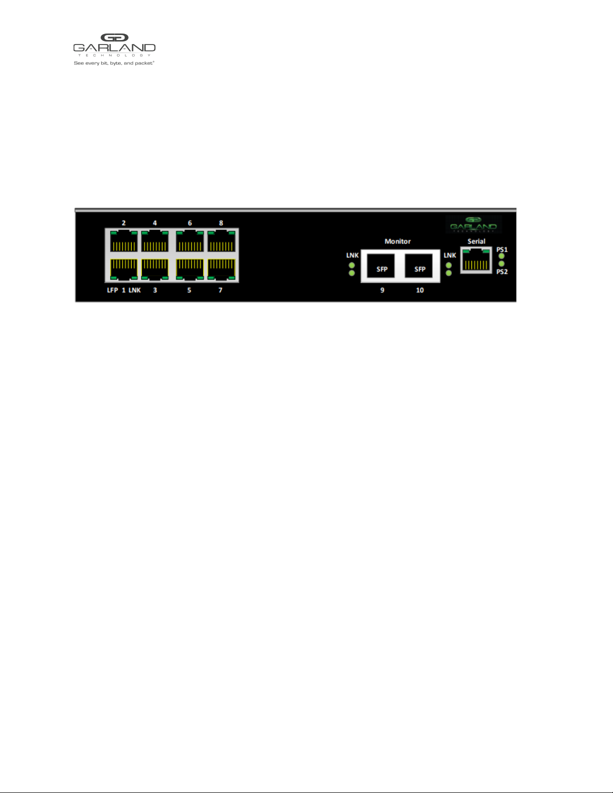
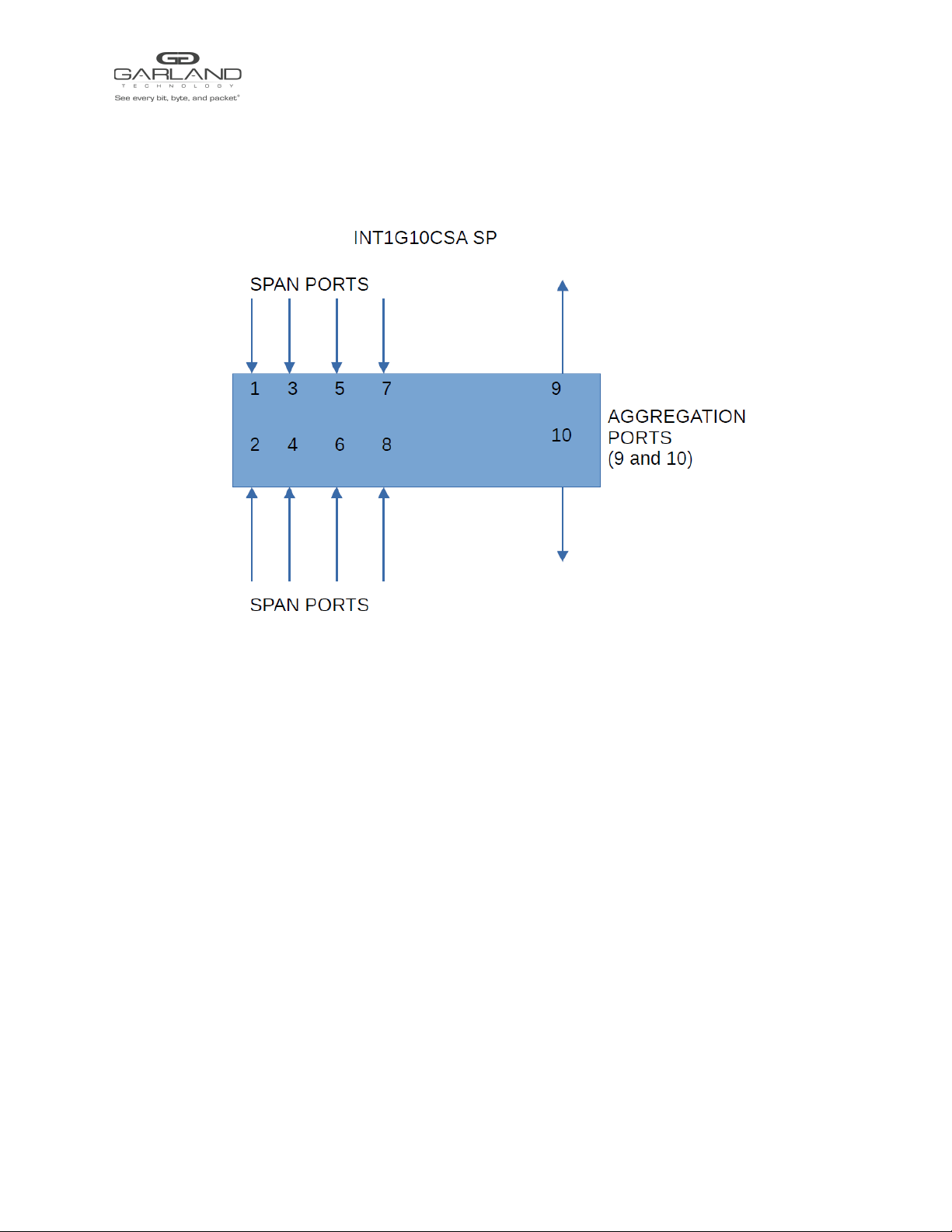
AggregatorTAP | INT1G10CSASP |1.1.37
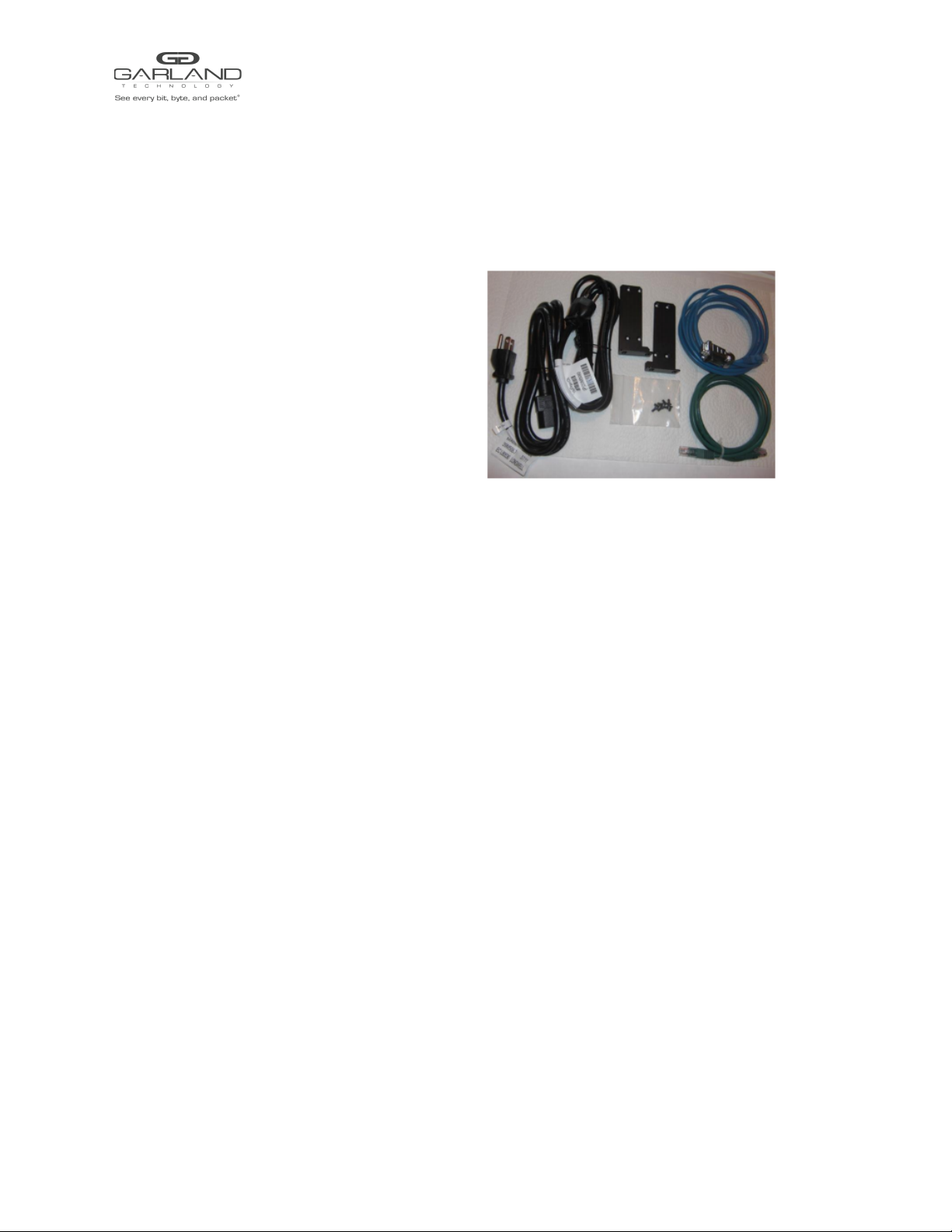
List of Components Supplied
The components supplied with each INT1G10CSASP tap are listed below. If any component is found to
be missing, damaged, not working, or otherwise faulty, please report it immediately to Garland
Technology Technical Support.
1 x INT1G10CSASP Span Tap
1 x Rack mounting kit (bracket and screws)
2 x AC Power Cords
1 x Ethernet Cable (RJ45)
1 x Console Cable (RJ45 x DB9)
Rack-mounting the Chassis
This section describes how to mount the INT1G10CSASP into a 19” rack. Follow the usual security
precautions.
To rack mount the INT1G10CSASP:
1. Unpack the INT1G10CSASP and place it on a suitable work surface.
2. Attach the two mounting brackets supplied to the side of the INT1G10CSASP chassis.
3. Slide the chassis into the rack and secure it with screws (not supplied).
4. Attached the AC Power cords to seperate power sources. The INT1G10CSASP is able to work
with a single power input but two power inputs from seperate power sources will help safeguard
the device against power failure.
If the INT1G10CSASP is DC powered, see connection instructions below.
To wire a DC power supply:
1. Verify the power is off to the DC input circuit.
2. Attach the appropriate ring fittings to the DC input wires.
3. From the bottom of the terminal block wire the DC input power supply to the terminal block as
follows:
Ground wire to Ground terminal (left)
-48 Vdc return to “+” terminal (center)
-48 Vdc wire to “-” terminal (right)
Caution: Before performing this procedure, ensure that all power is off to the DC circuit or the power
supply being added or removed. Locate the circuit breaker that services the DC circuit and switch it to the
off position. Tape the circuit breaker switch handle in the off position to prevent accidental closing of the
circuit.
Garland Technology | 716.242.8500 | garlandtechnology.com/support
Copyright © 2021 Garland Technology, LLC. All rights reserved. 2