Garland M100G1AC User manual

USER GUIDE
EdgeSafe Bypass | M100G1xx
Copyright © 2021 Garland Technology, LLC. All rights reserved.
No part of this document may be reproduced in any form or by any means without prior written permission of Garland
Technology, LLC.
The Garland Technology trademarks, service marks ("Marks") and other Garland Technology trademarks are the property of
Garland Technology, LLC. EdgeSafe Series products of marks are trademarks or registered trademarks of Garland
Technology, LLC. You are not permitted to use these Marks without the prior written consent of Garland Technology.
All other trademarks and trade names mentioned in this document are the property of their respective holders.
Notice
The purchased products, services and features are stipulated by the contract made between Garland Technology and the
customer. All or part of the products, services and features described in this document may not be within the purchase scope
or the usage scope. Unless otherwise specified in the contract, all statements, information, and recommendations in this
document are provided "AS IS" without warranties, guarantees or representations of any kind, either express or implied.
The information in this document is subject to change without notice. Every effort has been made in the preparation of this
document to ensure accuracy of the contents, but all statements, information, and recommendations in this document do not
constitute the warranty of any kind, express or implied.
Garland Technology | 716.242.8500 | garlandtechnology.com/support
Copyright © 2021 Garland Technology, LLC. All rights reserved. 1

USER GUIDE
EdgeSafe Bypass | M100G1xx
1. Introduction
The Garland Technology’s EdgeSafe Bypass TAP (hereafter referred to as the M100G1AC) is an active
external bypass switch that protects network integrity from network failures and enhances network
maintenance. It generates heartbeat packets, and by detecting the flow of heartbeat packets, it controls the
operation mode of the network.
A Garland M100G1AC 1U Unit is a 1U host system which supports up to two 100G modules. A 100G module
supports one segment.
The following figure shows a Garland M100G1AC 1U Unit with two 100G modules.
Figure 1. M100G1AC 1U Unit with two 100G modules
The M100G1AC supports 100 Gigabit Ethernet Multi-mode Fiber (100GBase-SR4 and 100GBase-SR10) and
100 Gigabit Single-mode Fiber (100GBase-LR4) network standards. Either 100G module includes two
MPO/LC ports for network connection and two CFP4/CXP ports for the attached inline network system.
Garland Technology | 716.242.8500 | garlandtechnology.com/support
Copyright © 2021 Garland Technology, LLC. All rights reserved. 2

USER GUIDE
EdgeSafe Bypass | M100G1xx
The following table explains the items in a Garland M100G1AC 1U Unit shipment package. Depending on
your order, your shipment package comes with a 1U host system and one or two 100G modules.
M100G1AC
Number of
Modules
Module type
Power supply
Power cord
Intelligent
100G Switch
1U Box
1: One module
2: Two modules
100G module with
bypass
will show
BCSR4
BCLR4
BCSR10
Blank: 90-240 V
AC, Redundant -
hot swap
- 48V DC
Blank: No power
cord
-EU
-US
-CN
The following table explains different models of the Garland M100G1AC 1U Unit.
Part number (P/N)
Description
M1001Gxx
Bypass Switch 1U Host System
M100GSR10BP
4 ports 100 Gigabit CFP4 (SR4) fiber Intelligent Bypass
Switch module
M100GSR4BP
M100G1AC with one bypass segment - SR4
M100GLR4BP
M100G1AC with one bypass segment - LR4
Garland Technology | 716.242.8500 | garlandtechnology.com/support
Copyright © 2021 Garland Technology, LLC. All rights reserved. 3

USER GUIDE
EdgeSafe Bypass | M100G1xx
2. Features and specifications
This chapter introduces the key features, bypass specifications, and default configurations of the
M100G1AC.
2.1 Key features
The following sections explain the key features of M100G1AC.
2.1.1 Supported operation modes
The M100G1AC supports four modes of operation: Inline, Bypass, TAP and Linkdrop.
- In Inline mode, the M100G1AC diverts the network traffic to the attached inline network system.
This is the normal operation mode.
- In Bypass mode, the M100G1AC diverts the network traffic to another network system instead of
the attached inline network system.
- In TAP mode, the M100G1AC mirrors incoming traffic in port Net0 to port Mon0 and incoming traffic
in port Net1 to port Mon1.
- In Linkdrop mode, the M100G1AC disables the links on both network ports (Net0, Net1). It
simulates switch/router cable disconnection.
3. For detailed description of operation modes, see Chapter 4. Theory of
operation System management overview
A user can use a username and password to access the M100G1AC management interface via COM, SSH or
Web. The initial user name is admin and the default password is Garland2015.
The M100G1AC supports multiple users’ login.
The M100G1AC defines three types of user privileges to restrict user access:
-Admin: Full read-write access to all configurations (Bypass Configuration/System/User/ SNMP);
privileges to add, delete, or modify local users on the M100G1AC. The initial user account admin is
the only administrator account and no other administrator accounts are allowed to be created. This
administrator account cannot be deleted, and the privileges cannot be modified.
- Normal: Full read-write access to Bypass Configurations and read-only access to other
configurations (System/User/SNMP).
-Readonly: Read-only access to all configurations.
The Admin user can change everyone’s password. The Normal users and Readonly users can change only
their own password.
Garland Technology | 716.242.8500 | garlandtechnology.com/support
Copyright © 2021 Garland Technology, LLC. All rights reserved. 4

USER GUIDE
EdgeSafe Bypass | M100G1xx
3.1.1 Garland Technology Double Bypass Safe architecture
The M100G1AC is designed with the Garland Technology Double Bypass Safe architecture, which is based
on two bypass routing circuitries: an active bypass routing circuitry and a passive bypass routing circuitry.
When the active one fails, the passive one will be activated.
3.1.2 Configuration methods
The M100G1AC can be configured through the following methods:
- Simple command line interface (CLI), via a serial communication console port and an Ethernet port
using SSH
- Simple Web management interface
- Simple Network Management Protocol (SNMP)
3.1.3 Centralized management
The M100G1AC performs centralized management to all bypass segments in the system.
3.1.4 Power supplies
The M100G1AC comes with two redundant 90-240 V AC power supplies or two redundant -48 V DC power
supplies.
3.1.5 Summary of key features
The following list summarizes the key features of the M100G1AC:
Self-generating heartbeat packets - No driver or management port is required to generate pulses.
- Sets to Bypass when inline system failure is detected
- Sets to Bypass when inline system link failure is detected
- Sets to Bypass when inline software application system hang is detected
- Sets to Bypass on power failure
- Sets to Inline when inline system recovery is detected
- Double Safe Bypass architecture with two routing circuitries
- Centralized management
- Two on board Watch Dog Timer (WDT) controllers
- Software programmable timeout interval
- Enable/Disable software programmable WDT
- Independent Inline/Bypass/Tap/Linkdrop operation in every module
- Supports up to two 100G Bypass segments in a 1U chassis
- Simple command line interface for configuration via serial port
- SSH management interface via network management port
- Web GUI management interface via network management port
- Supports SNMP versions 1, 2c, 3 (SHA, AES)
- Supports remote log
- Support RADIUS
- Supports TACACS+
- Supports NTP
- Supports time zone
- Supports multi configuration backup
- Supports two-port link feature
- Two redundant power supplies
Garland Technology | 716.242.8500 | garlandtechnology.com/support
Copyright © 2021 Garland Technology, LLC. All rights reserved. 5

USER GUIDE
EdgeSafe Bypass | M100G1xx
- Optional: - 48V dc power supplies
M1001Gxx
- Supports Short Range Fiber 100 Gigabit Ethernet (100GBase-SR4 50um).
M1001Gxx
- Supports Long Reach Fiber 100 Gigabit Ethernet (100GBase-LR4).
M1001Gxx
- Supports Short Range (100m) Fiber 100 Gigabit Ethernet with Optical module CXP (100GBase-SR10).
3.2 Bypass specifications
Item
Description
WDT interval (software
programmable
Routing
Transmit heartbeat packets every 3ms - 10sec (Default: 5ms)
Verify packets received every 10ms - 50sec (Default: 20ms)
Double Bypass
Transmit heartbeat packets every 300ms - 60sec (Default: 7sec)
Verify packets received every 1S - 253sec (Default: 20sec)
3.2 Bypass specifications
Item
Default configuration
Mode at power-up
Bypass
Heartbeat
Activated
Bypass switch is ready and inline device
responds to heartbeat
Change to Inline
Inline device responds to heartbeat
Normal
Inline device does not forward heartbeat
Bypass
Mode at power-off
Bypass
Heartbeat packet
Internetwork Packet Exchange
Garland Technology | 716.242.8500 | garlandtechnology.com/support
Copyright © 2021 Garland Technology, LLC. All rights reserved. 6

USER GUIDE
EdgeSafe Bypass | M100G1xx
4. System management overview
A user can use a username and password to access the M100G1AC management interface via COM, SSH or
Web. The initial user name is admin and the default password is Garland2015.
The M100G1AC supports multiple users’ login.
The M100G1AC defines three types of user privileges to restrict user access:
- Admin: Full read-write access to all configurations (Bypass Configuration/System/User/ SNMP);
privileges to add, delete, or modify local users on the M100G1AC. The initial user account admin is
the only administrator account and no other administrator accounts are allowed to be created. This
administrator account cannot be deleted, and the privileges cannot be modified.
- Normal: Full read-write access to Bypass Configurations and read-only access to other
configurations (System/User/SNMP).
- Readonly: Read-only access to all configurations.
The Admin user can change everyone’s password. The Normal users and Readonly users can change only
their own password.
The M100G1AC supports RADIUS/TACACS+ remote login. RADIUS and TACACS+ cannot be enabled at the
same
time. To enable either, the other needs to be disabled first.
RADIUS users share the same privilege level, which can be configured through Web or CLI.
TACACS+ user or user group privilege can be configured on server side by adding a service tag (default is
“silc-system”, which can be configured through Web or CLI) to tacacs+ server configuration as below:
service = silc-system {
# 1: readonly; 5: normal; 10: admin
user-privilege = 10
}
And TACACS+ user will be assigned Readonly privilege if the service tag is missing in server configuration.
Garland Technology | 716.242.8500 | garlandtechnology.com/support
Copyright © 2021 Garland Technology, LLC. All rights reserved. 7

USER GUIDE
EdgeSafe Bypass | M100G1xx
5. Theory of operation
5.1 Module and Segments
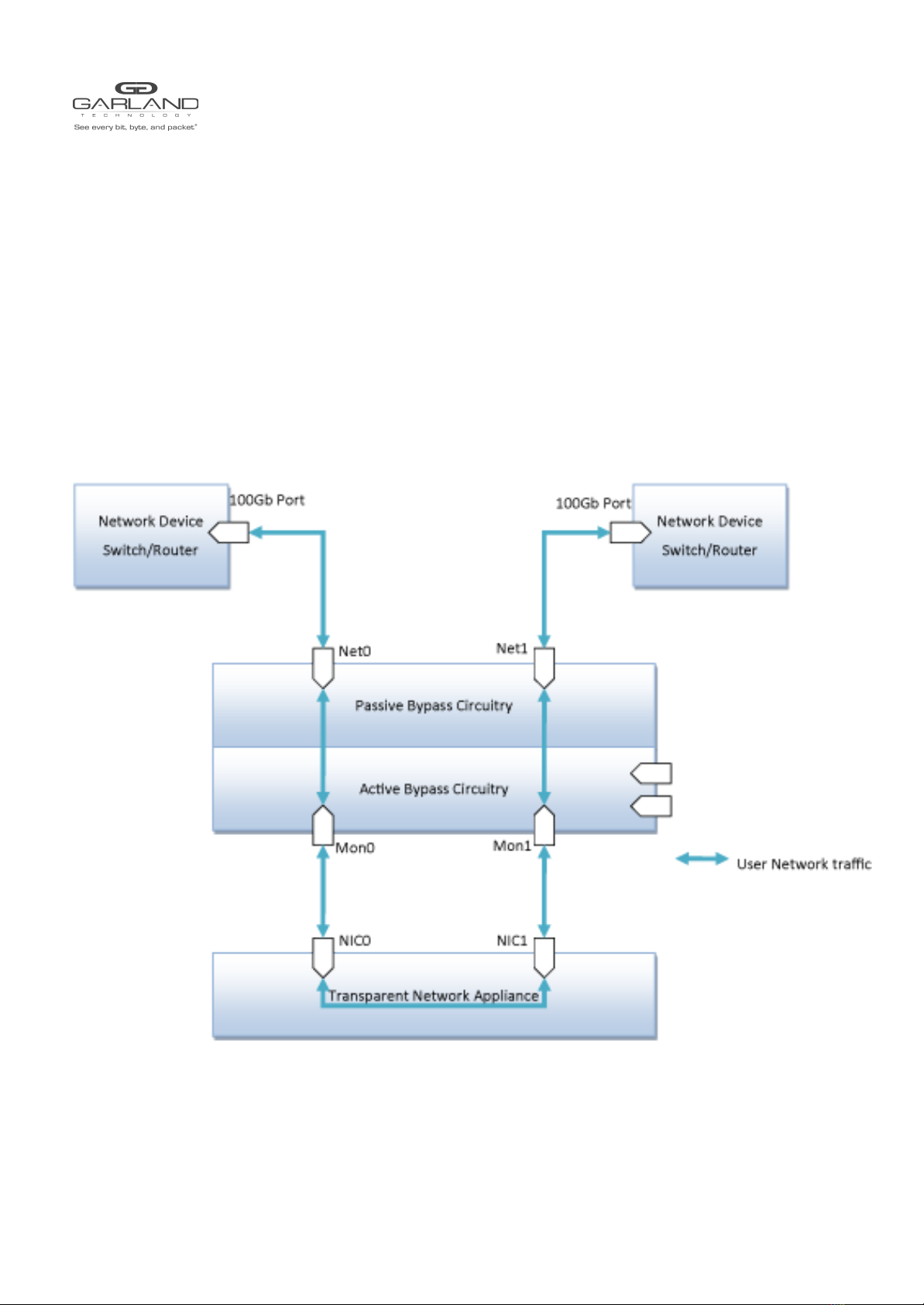
The M100G1AC bypass operation is provided at the segment level.
M100G1AC system can have a maximum of two modules, and each module may have a maximum of 1
100G
bypass segment.
In each M100G1AC bypass segment there are always 4 ports, two of them are named NET ports NET0 and
NET1, and the other two ports are named MON ports MON0 and MON1.
The two external ports connected to the NET ports are usually switch or router ports, and we refer to them
as Router Ports within the document.
The two external ports connected to the MON ports are usually from an Inline Network Appliance (A
Firewall for example), and we refer to them as Appliance Ports within the document.
5.2 Modes of operation
Each bypass segment supports the following predefined operation modes
- Inline - the M100G1AC diverts the network traffic to the attached inline network system. This is the
normal operation mode.
- Bypass - the M100G1AC diverts the network traffic to another network system instead of the
attached inline network system.
- In TAP mode, the M100G1AC mirrors incoming traffic in port Net0 to port Mon0 and incoming traffic
in port Net1 to port Mon1.
- In Linkdrop mode, the M100G1AC disables the links on both network ports (Net0, Net1). It simulates
switch/router cable disconnection.
By default, the M100G1AC operate in Inline mode. When traffic is received on the NET ports, it will be
forwarded to the Appliance Ports via the corresponding MON ports. The network appliance will need to
work like a network bridge for the two Router ports to communicate with each other.
Each bypass segment in inline mode will continuously transmit pre-defined heartbeat packets to the
Appliance Ports via the MON ports. When receiving a heartbeat packet from one of the MON ports, the
Inline Network appliance will need to forward it to the other MON ports, to bridges the heartbeat packet.
As long as the M100G1AC detects the flow of heartbeat packets, it stays in Inline mode.
When one of the following events occurs, the Inline Network Appliance fails to receive or forward the
heartbeat packets, and the M100G1AC will not be able to detect the flow of heartbeat packets, then the
M100G1AC
switches from Inline mode to Active Bypass, TAP, or Linkdrop mode according to the predefined settings
of the Heartbeat Active Expire OP Mode parameter:
- Application failure
- Monitor link is down
- Power failure (Will switch to Passive bypass or LinkDrop).
- User’s request to bypass the heartbeat packets manually
When the Inline Network Appliance recovers and resumes heartbeat packet transmission and the
M100G1AC will switch back to Inline mode.
Garland Technology | 716.242.8500 | garlandtechnology.com/support
Copyright © 2021 Garland Technology, LLC. All rights reserved. 8

USER GUIDE
EdgeSafe Bypass | M100G1xx
5.2.1 Inline mode
The following diagram illustrates the working mechanism of Inline mode.
The network appliance can then choose to reject packets received or inject packets into the network.
Since that network appliance may have down time, so it will affect the connection between the two
external Switch/router ports. This is where heartbeat and bypass mode will help.
EdgeSafe Bypass TAP
Inline mode
Figure 2. M100G1AC Inline mode
Garland Technology | 716.242.8500 | garlandtechnology.com/support
Copyright © 2021 Garland Technology, LLC. All rights reserved. 9

USER GUIDE
EdgeSafe Bypass | M100G1xx
5.2.2 Inline mode with heartbeat checking
In event of an application failure (including power failure of the monitor/network device), the
monitor/network device stops transmitting the heartbeat packets, and the M100G1AC will not be able to
detect the flow of heartbeat packets, then the M100G1AC switches from Inline mode to Active Bypass,
TAP, or Linkdrop mode according to the predefined settings of the Heartbeat Active Expire OP Mode
parameter.
In Active Bypass or TAP mode, the network traffic continues to flow through the network ports and is not
diverted to the monitor ports. As soon as the monitor/network device recovers and resumes transmitting
the heartbeat packets, the M100G1AC resumes Inline mode after detecting the heartbeat packets for a
period of time set by the hb_holdtime parameter.
EdgeSafe Bypass TAP
Inline mode
Figure 3. M100G1xx Heartbeat detection with Inline mode
Garland Technology | 716.242.8500 | garlandtechnology.com/support
Copyright © 2021 Garland Technology, LLC. All rights reserved. 10

USER GUIDE
EdgeSafe Bypass | M100G1xx
5.2.3 Bypass Mode (Active Bypass Mode)
The following diagram illustrates the working mechanism of Bypass mode or Active Bypass mode.
In this mode, traffic will bypass the M100G1AC device, which means packets received from Net0 port will be
forwarded to the device connected to NET1 port,Packets received from Net1 port will be forwarded to the
device connected to NET0 port. The mode is also called Active Bypass mode, as packets are actually going
through the switch circuitry.
EdgeSafe Bypass TAP
Bypass mode
Figure 4. M100G1xx Heartbeat detection with Bypass mode
Garland Technology | 716.242.8500 | garlandtechnology.com/support
Copyright © 2021 Garland Technology, LLC. All rights reserved. 11

USER GUIDE
EdgeSafe Bypass | M100G1xx
5.2.4 Passive Bypass and Power failure
In event of a power failure, the M100G1AC bypasses the Ethernet ports by switching to Passive Bypass
mode.
The network traffic continues to flow through the network ports but is not diverted to the monitor ports.
When power is restored, the M100G1AC resumes Inline mode after detecting the heartbeat packets for a
period of time set by the Heartbeat Expire Timer parameter.
Note: The Heartbeat Expire Timer parameter can be change via management port from their initial default value.
The following diagram illustrates the working mechanism of Passive Bypass mode.
EdgeSafe Bypass TAP
Passive Bypass mode
Figure 5. M100G1xx Passive Bypass mode
Garland Technology | 716.242.8500 | garlandtechnology.com/support
Copyright © 2021 Garland Technology, LLC. All rights reserved. 12

USER GUIDE
EdgeSafe Bypass | M100G1xx
5.2.5 TAP mode
In TAP mode, incoming traffic in port Net0 is mirrored to port Mon0 and incoming traffic in port Net1 is
mirrored to port Mon1.
The following diagram illustrates the working mechanism of TAP mode.
EdgeSafe Bypass TAP
TAP mode
Figure 6. M100G1xx TAP mode
Garland Technology | 716.242.8500 | garlandtechnology.com/support
Copyright © 2021 Garland Technology, LLC. All rights reserved. 13

USER GUIDE
EdgeSafe Bypass | M100G1xx
5.2.6 TAPI12 mode
When TAPI12 mode is enabled, incoming traffic in port Net0 is mirrored to port Mon0 and incoming traffic
in port Net1 is mirrored to port Mon1. Packets can be injected from port Mon0 to port Net0 and from port
Mon1 to port Net1.
The following diagram illustrates the working mechanism of TAPI12 mode.
EdgeSafe Bypass TAP
TAPI12 mode
Figure 7. M100G1xx TAPI12 mode
Garland Technology | 716.242.8500 | garlandtechnology.com/support
Copyright © 2021 Garland Technology, LLC. All rights reserved. 14

USER GUIDE
EdgeSafe Bypass | M100G1xx
5.2.7 TAPA mode
When TAPA mode is enabled, incoming traffic in port Net0 is mirrored to both monitor ports (Mon0, Mon1)
and incoming traffic in port Net1 also is mirrored to both monitor ports (Mon0, Mon1).
The following diagram illustrates the working mechanism of TAPA mode.
EdgeSafe Bypass TAP
TAPA mode
Figure 8. M100G1AC TAPA mode
Garland Technology | 716.242.8500 | garlandtechnology.com/support
Copyright © 2021 Garland Technology, LLC. All rights reserved. 15

USER GUIDE
EdgeSafe Bypass | M100G1xx
5.2.8 TAPAI1 mode
When TAPAI1 mode is enabled, incoming traffic in port Net0 is mirrored to both monitor ports (Mon0,
Mon1) and incoming traffic in port Net1 also is mirrored to both monitor ports (Mon0, Mon1). Packets can
be injected from port Mon0. Injected packets from Mon0 will be sent to both network ports (Net0, Net1).
The following diagram illustrates the working mechanism of TAPAI1 mode.
EdgeSafe Bypass TAP
TAPAI1 mode
Figure 9. M100G1AC TAPAI1 mode
Garland Technology | 716.242.8500 | garlandtechnology.com/support
Copyright © 2021 Garland Technology, LLC. All rights reserved. 16

USER GUIDE
EdgeSafe Bypass | M100G1xx
5.2.9 TAPAI2 mode
When TAPAI2 mode is enabled, incoming traffic in port Net0 is mirrored to both monitor ports (Mon0,
Mon1) and incoming traffic in port Net1 also is mirrored to both monitor ports (Mon0, Mon1). Packets can
be injected from port Mon1 to both network ports (Net0, Net1).
The following diagram illustrates the working mechanism of TAPAI2 mode.
EdgeSafe Bypass TAP
TAPAI2 mode
Figure 10. M100G1AC TAPAI2 mode
Garland Technology | 716.242.8500 | garlandtechnology.com/support
Copyright © 2021 Garland Technology, LLC. All rights reserved. 17

USER GUIDE
EdgeSafe Bypass | M100G1xx
5.2.10 TAPAI12 mode
When TAPAI12 mode is enabled, incoming traffic in port Net0 is mirrored to both monitor ports (Mon0,
Mon1) and incoming traffic in port Net1 also is mirrored to both monitor ports (Mon0, Mon1). Packets can
be injected from each monitor port to both network ports (Net0, Net1).
The following diagram illustrates the working mechanism of TAPAI12 mode.
EdgeSafe Bypass TAP
TAPAI12 mode
Figure 11. M100G1AC TAPAI12 mode
Garland Technology | 716.242.8500 | garlandtechnology.com/support
Copyright © 2021 Garland Technology, LLC. All rights reserved. 18

USER GUIDE
EdgeSafe Bypass | M100G1xx
5.2.11 Linkdrop mode
In Linkdrop mode, the M100G1AC disables the link on both network ports (Net0, Net1). The M100G1AC
simulates switch/router cable disconnection.
The following diagram illustrates the working mechanism of Linkdrop mode.
Linkdrop mode
Figure 12. M100G1xx Linkdrop mode
Garland Technology | 716.242.8500 | garlandtechnology.com/support
Copyright © 2021 Garland Technology, LLC. All rights reserved. 19
This manual suits for next models
1
Table of contents
Other Garland Measuring Instrument manuals