Garland M10G BP Series User manual

To deploy the M10GxxBP modular tap system into your network, simply:
Carefully unpack and inspect the tap modules and system chassis.
Insert and fully seat the M10GxxBP modules into the M10Gxxxx chassis and secure modules using both screws.
Install the tap and chassis assembly into any available 1U slot of a network rack and secure it with rack mount screws.
Connect the power supply to the M10GxxBP and plug it into an available power source and turn on the power switch. Note:
A VLAN message on the LCD screen is normal.
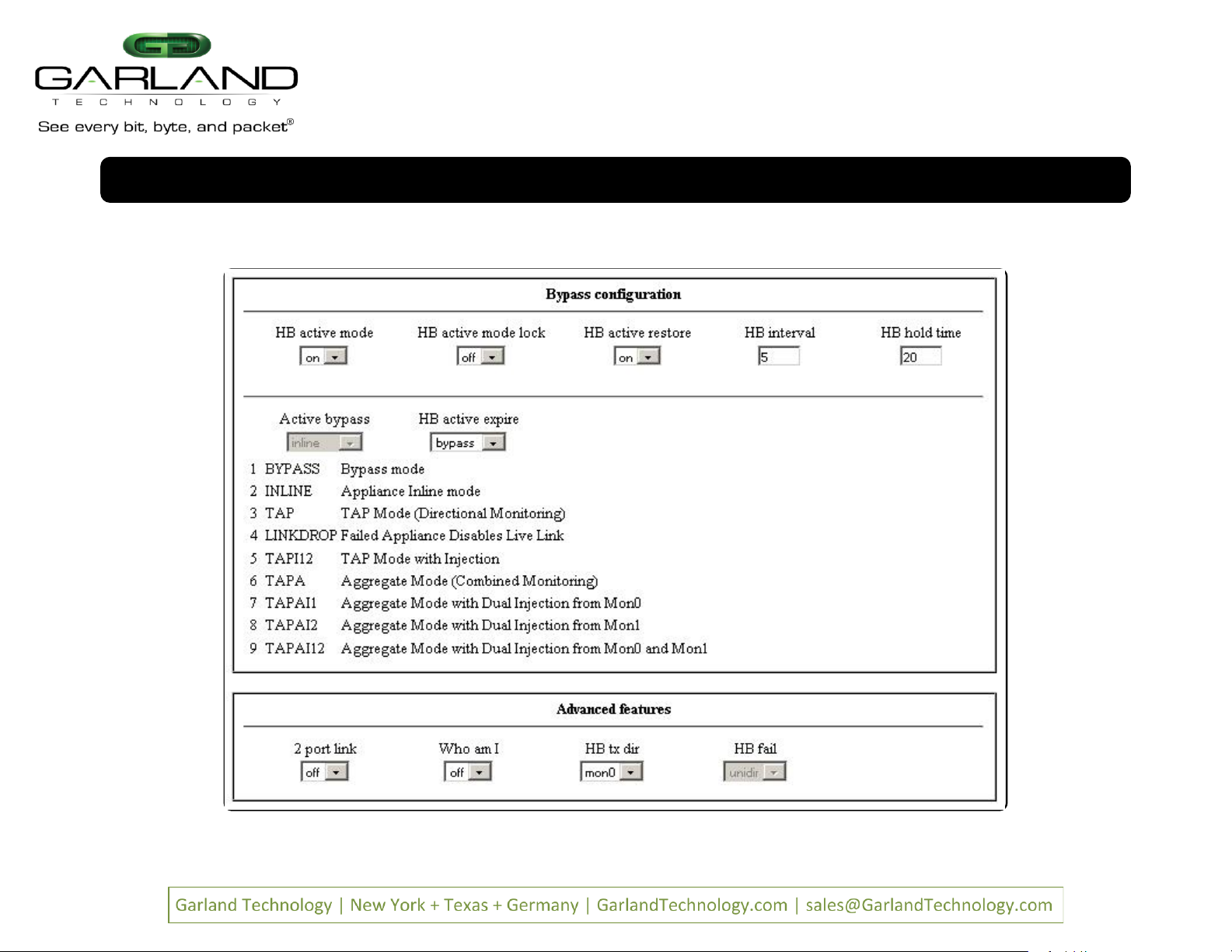
Utilizing the CLI or GUI, configure the M10GxxBP for the operating mode of your choice (default is bypass mode).
Remove the power supply to the M10Gxxxx chassis temporarily.
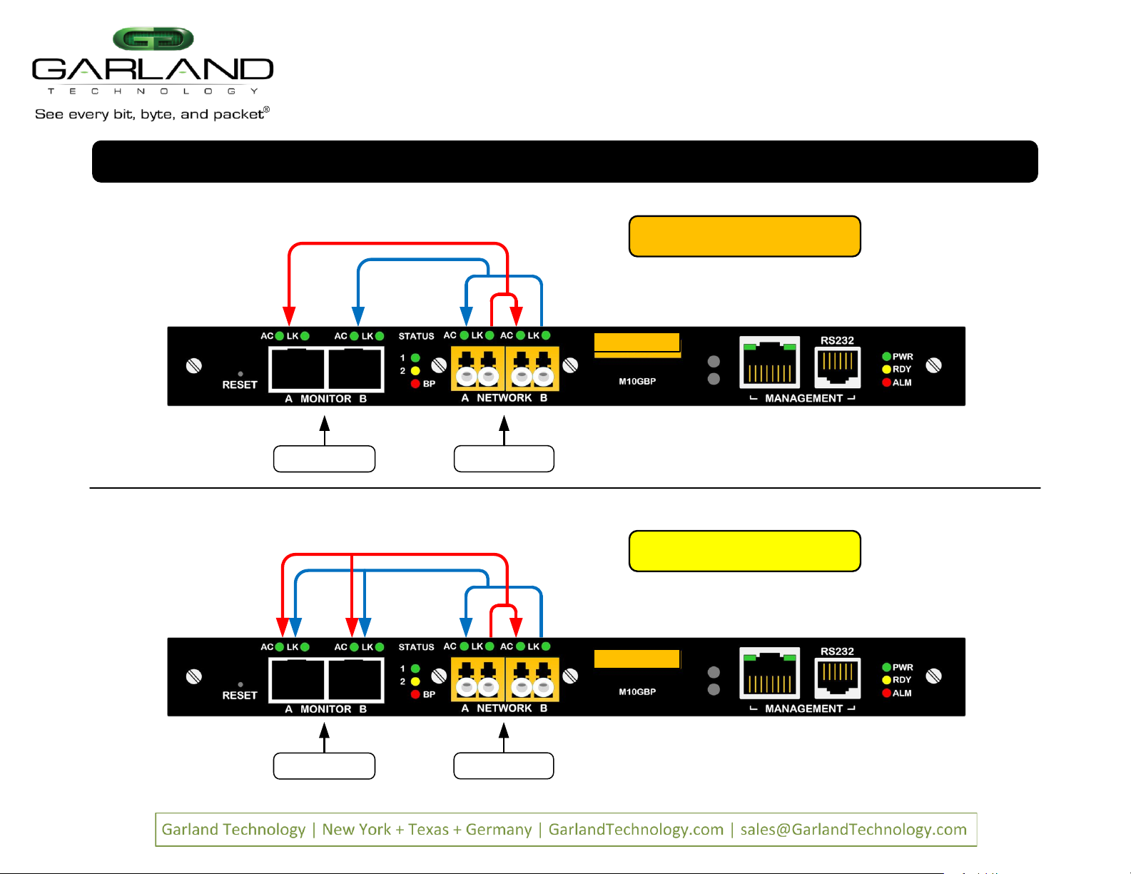
Using standard Ethernet cables, connect NETWORK ports [A] and [B] of the M10GxxBP between the two live network devices where you would otherwise deploy an inline
appliance or sensor (for example: IPS or DLP). Verify network traffic is flowing, confirming that network cabling is correct.
Connect MONITOR ports [A] and [B] to the inline IPS/DLP appliance or other tools for traditional breakout or aggregated traffic monitoring.
Connect the power leads to the M10Gxxxx chassis power supplies and plug it into an available power source. Turn on the chassi s power switch. Note:
A VLAN message on the
LCD screen is normal.
Notes: * Fiber is always 10Gbps speed. Other operating modes may be desired for monitoring and may be configured using the CLI or GUI.
* If you wish to replace one of the modules in a chassis without shutting the power to the entire chassis, you need to remov e power to the module that you wish to replace
through the CLI using the power_offcommand. See Sub-paragraphs 6.56.8 and 6.56.9 on page 69 of the User Guide.
M10GxxBP Series Modular Tap
Installation Guide
AC Power Input DC Power Input
Fiber Active Bypass Modules IP & Serial Management
GN D N EGPOS
Pg 1 Ver 2.2.1

M10GxxBP Series Modular Tap
Installation Guide
LFP or Link Failure Propagation: Allows link state to be mirrored to adjacent live network interfaces. When one side of a network loses link on a
connecting tap, the link state is propagated to the other interface of the tap and ultimately to the other side of the network. Enabled by default.
LK or Link/Activity: Solid when link is achieved and flashes when data is detected on an interface.
BP or Bypass: A mode that allows active temporary bypass of an inline appliance or sensor type IPS/DLP device. Bypass is based on the ope rating
characteristics of the connected network appliance. When a bypass tap device is not able to detect link or heartbeats from (or through) inline appliance
or sensor connecting to the C and D sensor port pair, the appliance is bypassed automatically, keeping link up and networks online and passing data.
Aggregation: Combines data flows for full-duplex monitoring on a single interface. Ideal when monitoring both sides of network traffic simultaneously.
Breakout: Separates data flows for half-duplex directional monitoring. Ideal when utilization is very high and packet loss is not an option.
SPAN or Regenerate: Allows users to multiply one or more inputs into many outputs. BP LEDs are not used while this mode is configured.
FailSafe: On power loss, live network tap ports re-establish link with each other, resuming traffic flow between critical network devices. Always on.
Reverse Bypass: Disables link on both live network ports if all inline appliances lose link or cannot pass traffic. Disabled by default.
Packet Injection: Allows monitor ports to inject Ethernet frames back into the live network flows.
1. Reset
2. Monitor Port A
3. Monitor Port B
4. Watchdog Timer LED
5. Bypass Mode
LED
6. Network Port A
7. Network Port B
8. Push Button 1
9 Management Network Port
10 Management RS-232 Port
11. System
OK LED
12 Alarm LED
13. Monitor Port A LED
24. Power ON LED
23. Push Button 0
22. LCD
21. Network Port B
Link LED
20. Network Port B
Activity LED
19. Network
A Link LED
18. Network Port A
Activity LED
14. Monitor
Port A Link
LED
15. Monitor Port B Activity LED
16. Monitor
Port B Link LED
17. Normal Mode
LED
Pg 2 Ver 2.2.1

M10GxxBP Tap Module Operating Modes
Bypass (auto)
Live NetworkSensor Online
M10GxxBP Series Modular Tap
Installation Guide
Bypass (active)
Live NetworkSensor Offline
Pg 3 Ver 2.2.1

A B
A B
1 2
Garland Bypass Tap
IPS Appliance
Figure 1: Normal Operation (IPS Online)
All Data Passes Through Sensor Inline
A B
A B
1 2
Garland Bypass Tap
IPS Appliance
Figure 2: Active Bypass (IPS Offline)
Data and Heartbeats Copied to Sensor
A B
A B
1 2
Garland Bypass Tap
IPS Appliance
Figure 3: Passive Bypass (Power Failure)
Network Interfaces Renegotiate Resuming Flow
Router Switch Router Switch Router Switch
M10GxxBP Series Modular Tap
Installation Guide
Bypass Mode Detail
Pg 4 Ver 2.2.1

Live Network
M10GxxBP Tap Module Operating Modes
Aggregate (TAPA)
M10GxxBP Series Modular Tap
Installation Guide
Monitor Ports
Live Network
Monitor Ports
Breakout (TAP)
TAP
TAPA
Pg 5 Ver 2.2.1

TAPI12
Live Network
M10GxxBP Tap Module Operating Modes
Aggregate (TAPAI12)
M10GxxBP Series Modular Tap
Installation Guide
Monitor Ports
Live Network
Monitor Ports
Breakout (TAPI12)
Dual Packet Injection
TAPAI12
Pg 6 Ver 2.2.1

Live Network
M10GxxBP Tap Module Operating Modes
Aggregate (TAPAI2)
M10GxxBP Series Modular Tap
Installation Guide
Monitor Ports
Packet Injection MON B
Live Network
Aggregate (TAPAI1)
Monitor Ports
Packet Injection MON A
TAPAI1
TAPAI2
Pg 7 Ver 2.2.1

M10GxxBP Series Modular Tap
Installation Guide
Web Interface Orientation
Default Login Credentials
admin | gtadmin1
Pg 8 Ver 2.2.1

M10GxxBP Series Modular Tap
Installation Guide
Web Interface Orientation
Pg 9 Ver 2.2.1

M10GxxBP Series Modular Tap
Installation Guide
Web Interface Orientation
Pg 10 Ver 2.2.1

M10GxxBP Series Modular Tap
Installation Guide
Web Interface Orientation
Pg 11 Ver 2.2.1

M10GxxBP Series Modular Tap
Installation Guide
Web Interface Orientation
Pg 12 Ver 2.2.1

M10GxxBP Series Modular Tap
Installation Guide
Web Interface Orientation
Pg 13 Ver 2.2.1

M10GxxBP Series Modular Tap
Installation Guide
Web Interface Orientation
Pg 14 Ver 2.2.1

M10GxxBP Series Modular Tap
Installation Guide
Web Interface Orientation
Pg 15 Ver 2.2.1

M10GxxBP Series Modular Tap
Installation Guide
Serial Console Cable Pinout
Pg 16 Ver 2.2.1

I. Serial Console Settings
M10GxxBP administrators may gain access to the command line
interface environment using a serial terminal emulator console using
the settings below:
Bits per second: 115200
Data bits: 8
Parity: None
Stop: 1
Flow Control: None
II. Login Credentials
The adminaccount grants full access and permission to a device.
The default password for admin is gtadmin1Administrators may
change the default login credentials by issuing the following commands:
Set_usr Changes the user account login name
Set_psw Changes the user account password
III. Command Help
M10GxxBP allows commands for configuring each module
independently. Command help may be issued by executing the
following commands:
Help Provides a list of all show and set type
commands
Help full Provides a list of all show and set commands
including a detailed description of each
command and its usage
Exit Logs out and exits the command line interface
IV. IP Management Interface
M10GxxBP system administrators may choose to manage the device via
the provided Ethernet port. The default IP address parameters are:
Address: 10.10.10.200
Netmask: 255.255.0.0
Gateway: 0.0.0.0
M10GxxBP system administrators may set the Ethernet management
ports IP address parameters with the following commands:
Set_ip Configures an IPv4 address
Set_netmask Configures an IPv4 subnet mask
Set_gateway Configures an IPv4 default network gateway
V. Web Interface Login
M10GxxBP system administrators may choose to configure and manage
devices via web or graphical user interface. After changing the
management ports IP address, you have the option to access the
graphical user interface using a web browser application, such as
Google Chrome or Mozilla Firefox. Simply browse to your devices
assigned IP address and login using the login credentials:
Address: http://10.10.10.200
Username: admin
Password: gtadmin1
*For product support and inquiries visit: www.garlandtechnology.com
M10GxxBP Series Modular Tap
Installation Guide
This document is for informational purposes only. The information in this document, believed by Garland Technology to be accurate as of the date of publication, is subject to change without notice. Garland Technology assumes no responsibility
for any errors or omissions in this document and shall have no obligation to you as a result of having made this document available to you or based upon the information it contains. Copyright 2016 Garland Technology LLC. All rights reserved.
Pg 17 Ver 2.2.1
Table of contents
Other Garland Measuring Instrument manuals