Garmin GIA 63 User manual

190-00303-05 November, 2010 Revision T
GIA 63
Installation Manual
DRAFT Rev T 11/12/2010

Page A GIA 63 Installation Manual
Revision T 190-00303-05
© Copyright 2010
Garmin Ltd. or its subsidiaries
All Rights Reserved
Except as expressly provided herein, no part of this manual may be reproduced, copied, transmitted, disseminated, downloaded
or stored in any storage medium, for any purpose without the express prior written consent of Garmin. Garmin hereby grants
permission to download a single copy of this manual and of any revision to this manual onto a hard drive or other electronic
storage medium to be viewed and to print one copy of this manual or of any revision hereto, provided that such electronic or
printed copy of this manual or revision must contain the complete text of this copyright notice and provided further that any
unauthorized commercial distribution of this manual or any revision hereto is strictly prohibited.
Garmin International, Inc.
1200 E. 151st Street
Olathe, KS 66062 USA
Telephone: 913-397-8200
Aviation Dealer Technical Support Line (Toll Free): (888) 606-5482
www.garmin.com
Garmin (Europe) Ltd
Liberty House
Bulls Copse Road
Hounsdown Business Park
Southampton, SO40 9RB, UK
Telephone: 44/ (0) 870.8501241
RECORD OF REVISIONS
Revision Revision
Date Description
A 11/15/04 Production Release
B 3/16/05
Updated pinout list, removed EQF and ETSO 2C37e deviation
C 6/23/05 Added additional interconnects, TSO-C9c, and TSO-C52b
D 10/26/05 Added TSO-C151b and boot block instructions
E 6/8/06 Edited document to include the GIA 63W
F 7/21/06 Corrected WAAS TSO
G 9/19/06 Added RTCA/DO-229C deviation
H 10/18/06 Added Comant antennas
J 4/10/07 Added Comant antenna and revised ICAW
K 6/6/07 Added the 011-01105-01 unit
L 8/23/07 Changed operational limitations and added antennas
M 2/29/08 Added ETSO information
N 5/27/09 Added TSO-C92c and other TSO info
P 09/09/09 Added Level A CLD information
Q 12/29/09 Added antenna note
R 03/23/10 Added standalone rack info
S 7/29/10 Added updated NAV/COM unit
T 11/10/10 Added GIA 63H model info
DRAFT Rev T 11/12/2010

GIA 63 Installation Manual Page i
190-00303-05 Revision T
CURRENT REVISION DESCRIPTION
Revision Page
Number(s)
Section
Number Description of Change
ii TOC Added reference to GIA 63H and note regarding GIA 63(X)
v, vi TOC Updated mod level tables
1-1–1-32 1
Updated to GIA 63(X) where applicable, added GIA 63 H
info and references throughout
1-3 1.4.2 Corrected weight info, added GIA 63H info
1-5 1.4.6 Updated Modulation Capability info
1-9 1.5 Updated Rated Power and Emission Type info
1-10 1.6 Added quantitative safety objective statement
1-22, 1-23 1.66 Added GIA 63H compliance table
2-1–2-16 2
Updated to GIA 63(X) where applicable, added GIA 63 H
info and references throughout
3-1–3-6 3
Updated to GIA 63(X) where applicable, added GIA 63 H
info and references throughout
4-1–4-30 4
Updated to GIA 63(X) where applicable, added GIA 63 H
info and references throughout
A-1 Appdx A Added GIA 63H to note
B-3, B-7 Appdx B Changed references to exclude 011-01105-3X units
B-9, B-11 Appdx B Added GIA 63H outline and installation drawings
T
C-1–C-13 Appdx C Updated references to GIA 63(X)
DOCUMENT PAGINATION
Section Page Range
Table of Contents i – vi
Section 1 1-1 – 1-32
Section 2 2-1 – 2-16
Section 3 3-1 – 3-6
Section 4 4-1 – 4-30
Appendix A A-1 – A-4
Appendix B B-1 – B-12
Appendix C C-1 – C-14
DRAFT Rev T 11/12/2010

Page ii GIA 63 Installation Manual
Revision T 190-00303-05
This manual reflects the operation of main software version 5.31 for the GIA 63 and main software
version 6.00 for the GIA 63W and GIA 63H. Some differences in operation may be observed when
comparing the information in this manual to earlier or later software versions.
INFORMATION SUBJECT TO EXPORT CONTROL LAWS
This document may contain information which is subject to the Export Administration Regulations
(“EAR”) issued by the United States Department of Commerce (15 CFR, Chapter VII Subchapter C) and
which may not be exported, released or disclosed to foreign nationals inside or outside the United States
without first obtaining an export license. The preceding statement is required to be included on any and
all reproductions in whole or in part of this manual.
WARNING
This product, its packaging, and its components contain chemicals known to the State of
California to cause cancer, birth defects, or reproductive harm. This Notice is being
provided in accordance with California's Proposition 65. If you have any questions or
would like additional information, please refer to our web site at
www.garmin.com/prop65.
WARNING
Perchlorate Material –special handling may apply, see
www.dtsc.ca.gov./hazardouswaste/perchlorate.
NOTE
References made to the GIA 63(X) throughout this document apply equally to the
GIA 63, the GIA 63H, and the GIA 63W except where specifically noted.
DRAFT Rev T 11/12/2010

GIA 63 Installation Manual Page iii
190-00303-05 Revision T
TABLE OF CONTENTS
PARAGRAPH PAGE
1 GENERAL DESCRIPTION..............................................................................................................1-1
1.1 Introduction........................................................................................................................................1-1
1.2 Equipment Description......................................................................................................................1-1
1.3 Interface Summary.............................................................................................................................1-2
1.4 Technical Specifications....................................................................................................................1-3
1.5 License Requirements........................................................................................................................1-9
1.6 Certification.....................................................................................................................................1-10
1.7 Referenced Documents....................................................................................................................1-30
1.8 Limited Warranty.............................................................................................................................1-31
2 INSTALLATION OVERVIEW........................................................................................................2-1
2.1 Introduction........................................................................................................................................2-1
2.2 Installation Considerations ................................................................................................................2-5
2.3 Rack Considerations..........................................................................................................................2-9
2.4 Cabling and Wiring..........................................................................................................................2-10
2.5 Cooling Air......................................................................................................................................2-10
2.6 GIA 63 Minimum Installation Requirements..................................................................................2-11
2.7 GIA 63W and GIA 63H Minimum Installation Requirements........................................................2-12
2.8 Mounting Requirements ..................................................................................................................2-13
3 INSTALLATION PROCEDURE......................................................................................................3-1
3.1 Unpacking Unit..................................................................................................................................3-1
3.2 Wiring Harness Installation...............................................................................................................3-1
3.3 Antenna Installation...........................................................................................................................3-2
3.4 Cable Installation ..............................................................................................................................3-2
3.5 Backshell Assembly...........................................................................................................................3-3
3.6 Unit Installation .................................................................................................................................3-3
3.7 Post Installation Configuration & Checkout......................................................................................3-4
3.8 Continued Airworthiness...................................................................................................................3-5
4SYSTEM INTERCONNECTS..........................................................................................................4-1
4.1 Pin Function List................................................................................................................................4-1
4.2 Power and Antennas ........................................................................................................................4-13
4.3 GIA System ID Program..................................................................................................................4-14
4.4 Serial Data .......................................................................................................................................4-14
4.5 Discrete I/O......................................................................................................................................4-17
4.6 COM/VOR/ILS/Digital Audio ........................................................................................................4-18
4.7 VOR/ILS Indicator ..........................................................................................................................4-20
4.8 RMI/OBI..........................................................................................................................................4-23
4.9 DME Tuning and ADF....................................................................................................................4-24
4.10 Auto Pilot.........................................................................................................................................4-26
DRAFT Rev T 11/12/2010

Page iv GIA 63 Installation Manual
Revision T 190-00303-05
PARAGRAPH PAGE
APPENDIX A GIA 63 MAIN BOOT BLOCK UPLOADING INSTRUCTIONS.................................A-1
A.1 Introduction.......................................................................................................................................A-1
A.2 Determining Current Boot Block......................................................................................................A-1
A.3 Loading Boot Block Version 4.01....................................................................................................A-2
A.4 Loading GIA Main Software (only if GIA main software was cancelled in Section A.2)...............A-3
APPENDIX B OUTINE & INSTALLATION DRAWINGS..................................................................B-1
APPENDIX C INTERCONNECT EXAMPLES.....................................................................................C-1
LIST OF FIGURES
FIGURE PAGE
2-1 GPS Antenna Considerations.............................................................................................................2-7
2-2 GIA 63(W) Modular Rack...............................................................................................................2-13
2-3 GIA 63(W) Standalone Rack...........................................................................................................2-14
2-4 GIA 63H Standalone Rack ..............................................................................................................2-15
2-5 GIA 63(W) Standalone Rack, Suggested Mounting Locations.......................................................2-16
3-1 Coaxial Cable Installation..................................................................................................................3-2
3-2 GIA STATUS Page ...........................................................................................................................3-6
B-1 GIA 63(W) Modular Installation Outline Drawing.......................................................................... B-1
B-2 GIA 63(W) Modular Installation Drawing.......................................................................................B-3
B-3 GIA 63(W) Standalone Installation Outline Drawing ......................................................................B-5
B-4 GIA 63(W) Standalone Installation Drawing...................................................................................B-7
B-5 GIA 63H Standalone Installation Outline Drawing..........................................................................B-9
B-6 GIA 63H Standalone Installation Drawing.....................................................................................B-11
C-1 GIA 63(X) Example Interconnect (Sheet 1 of 7)..............................................................................C-1
C-1 GIA 63(X) Example Interconnect (Sheet 2 of 7)..............................................................................C-3
C-1 GIA 63(X) Example Interconnect (Sheet 3 of 7)..............................................................................C-5
C-1 GIA 63(X) Example Interconnect (Sheet 4 of 7)..............................................................................C-7
C-1 GIA 63(X) Example Interconnect (Sheet 5 of 7)..............................................................................C-9
C-1 GIA 63(X) Example Interconnect (Sheet 6 of 7)............................................................................C-11
C-1 GIA 63(X) Example Interconnect (Sheet 7 of 7)............................................................................C-13
LIST OF TABLES
TABLE PAGE
3-1 Pin Contact Part Numbers..................................................................................................................3-1
3-2 Recommended Crimp Tools..............................................................................................................3-1
3-3 Long Term Power Interrupt Category A (200 mS) Mod Status ........................................................3-5
DRAFT Rev T 11/12/2010

GIA 63 Installation Manual Page v
190-00303-05 Revision T
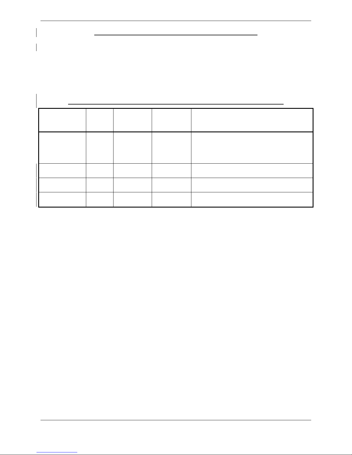
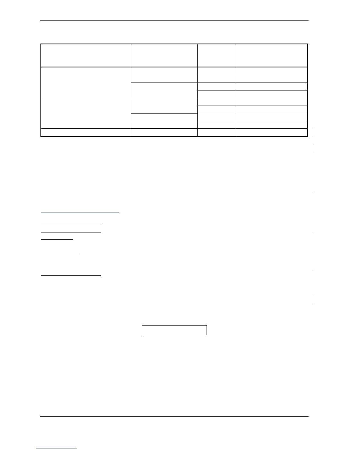
GIA 63 HARDWARE MOD LEVEL HISTORY
The following table identifies hardware modification (Mod) Levels for the GIA 63. Mod Levels are listed
with the associated service bulletin number, service bulletin date, and the purpose of the modification.
The table is current at the time of publication of this manual (see date on front cover) and is subject to
change without notice. Authorized Garmin Sales and Service Centers are encouraged to access the most
up-to-date bulletin and advisory information on the Garmin Dealer Resource web site at
www.garmin.com using their Garmin-provided user name and password.
GIA 63 P/N 011-00781-00, 011-00781-01 HARDWARE MOD LEVEL HISTORY
APPLICABLE
LRU PART
NUMBER
MOD
LEVEL
SERVICE
BULLETIN
NUMBER
SERVICE
BULLETIN
DATE
PURPOSE OF MODIFICATION
1 0416 9/13/2004
This modification consists of
modifying the voice alert audio output
circuit, enabling it to power down
when not in use.
2 0418 9/8/2004
This Service Bulletin consists of
visually inspecting the GIA 63 Main2
board for incorrectly installed
capacitors.
3 0505 1/19/2005
This modification addresses a
potential GIA 63 COM transceiver
interference condition.
011-00781-00
4 N/A N/A
More robust capacitors installed in the
power supply backup circuit.
011-00781-01 1 N/A N/A
More robust capacitors installed in the
power supply backup circuit.
DRAFT Rev T 11/12/2010
Page vi GIA 63 Installation Manual
Revision T 190-00303-05
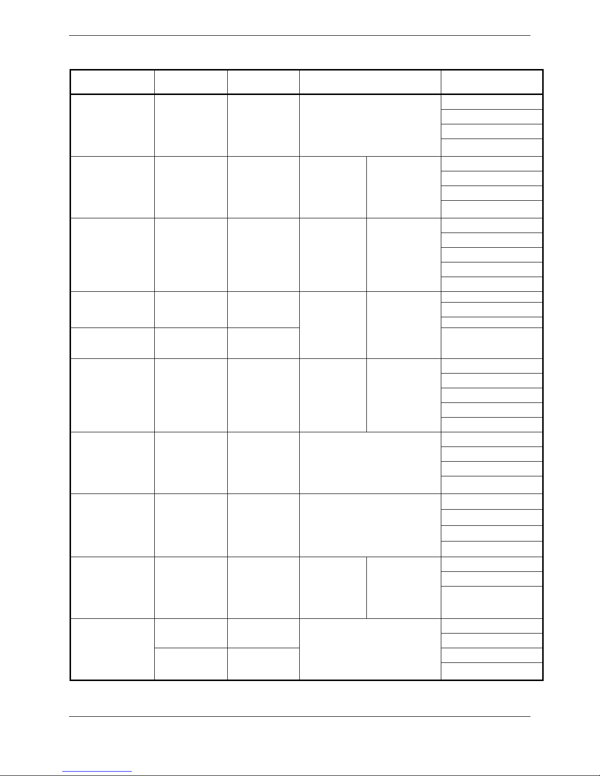
GIA 63W/GIA 63H HARDWARE MOD LEVEL HISTORY
The following table identifies hardware modification (Mod) Levels for the GIA 63W and GIA 63H. Mod
Levels are listed with the associated service bulletin number, service bulletin date, and the purpose of the
modification. The table is current at the time of publication of this manual (see date on front cover) and is
subject to change without notice. Authorized Garmin Sales and Service Centers are encouraged to access
the most up-to-date bulletin and advisory information on the Garmin Dealer Resource web site at
www.garmin.com using their Garmin-provided user name and password.
GIA 63W/GIA 63H P/N 011-01105-XX HARDWARE MOD LEVEL HISTORY
APPLICABLE
LRU PART
NUMBER
MOD
LEVEL
SERVICE
BULLETIN
NUMBER
SERVICE
BULLETIN
DATE
PURPOSE OF MODIFICATION
011-01105-00 1 N/A N/A More robust capacitors installed in the
power supply backup circuit.
011-01105-01 N/A N/A N/A N/A
011-01105-20 N/A N/A N/A N/A
011-01105-30 N/A N/A N/A N/A
DRAFT Rev T 11/12/2010

GIA 63 Installation Manual Page 1-1
190-00303-05 Revision T
1GENERAL DESCRIPTION
1.1 Introduction
This manual presents mechanical and electrical installation requirements for installing the GIA 63(X) as
part of a Garmin Integrated Flight Deck. The GIA 63(X) can be integrated into a variety of airframes
under an appropriate TC or STC. Each airframe installation may vary. Use only approved (type or
supplemental type) data for specific installation instructions in a particular aircraft.
1.2 Equipment Description
The GIA 63(X) is a microprocessor-based input/output Line Replaceable Unit (LRU) used in a Garmin
Integrated Flight Deck. The GIA 63(X) communicates with the GDU via Ethernet high-speed data bus
(HSDB), and with other LRUs using RS-232, RS-485/422, and ARINC 429. All configuration is done
through the GDU. The GIA 63(X) contains the following sub-assemblies:
•A main processor that interfaces with all LRUs in the G1000 sub-system and performs
calculations for the GFC 700 autopilot (if equipped).
•A twelve channel parallel GPS receiver that simultaneously tracks and uses up to 12 satellites.
The GIA 63W and GIA 63H include a 15 channel WAAS certified GPS receiver.
•A VHF COM transceiver that provides tuning from 118.00 to 136.992 MHz in 25 kHz or
8.33 kHz spacing for 760 or 2280 channel configuration respectively.
•A VOR/ILS localizer receiver that provides tuning from 108.00 to 117.95 MHz in 50 kHz
increments.
•An ILS glideslope receiver that provides tuning from 328.6 to 335.4 MHz as paired with the
frequency tuned on the VOR/ILS localizer receiver.
CAUTION
The operation of unapproved cellular telephones or other unapproved cellular devices
aboard aircraft while airborne is prohibited by FCC rules. Due to the potential for
interference with onboard systems, the operation of unapproved cellular communication
devices while onboard an aircraft that is on the ground is subject to FAA regulations
14 CFR 91.21.
FCC regulation 47 CFR 22.925 prohibits airborne operation of unapproved cellular
telephones installed in or carried aboard aircraft. Unapproved cellular telephones must
not be operated aboard any aircraft while the aircraft is off the ground. When any aircraft
leaves the ground, all unapproved cellular telephones on board that aircraft must be
turned off.
Unapproved cellular telephones that are on, even in a monitoring state, can disrupt GPS
performance.
DRAFT Rev T 11/12/2010

Page 1-2 GIA 63 Installation Manual
Revision T 190-00303-05
1.3 Interface Summary
1.3.1 Primary Interfaces
The GIA 63(X) is designed as an open architecture system that provides the following interfaces:
•1 dedicated Ethernet High-Speed Data Bus (HSDB) input/output channel
•2 Controller Area Network (CAN) I/O channels
•8 Main ARINC 429 inputs
•3 Main ARINC 429 outputs
•1 VOR/ILS ARINC 429 input
•1 VOR/ILS ARINC 429 output
•5 RS-485 input/output channels (any two RS-485 channels can be configured to form a single
RS-422 channel)
•8 RS-232 input/output channels
•41 Discrete inputs
•14 Discrete outputs
•24 Annunciator outputs
1.3.2 Additional Interfaces
The GIA 63(X) can provide interfaces for the following additional equipment:
•Autopilot
•Altitude encoder/serializer
•Fuel management systems
•Lightning detection systems
•Traffic awareness systems
•Data link systems
•External annunciators
•DME (including King Serial)
•ADF
DRAFT Rev T 11/12/2010

GIA 63 Installation Manual Page 1-3
190-00303-05 Revision T
1.4 Technical Specifications
1.4.1 Environmental Qualification Form
It is the responsibility of the installing agency to obtain the latest revision of the GIA 63(X)
Environmental Qualification Form. These forms are available directly from Garmin under the following
part numbers:
GIA 63 Environmental Qualification Form, Garmin part number 005-00148-02
GIA 63W Environmental Qualification Form, Garmin part number 005-00235-00
The GIA 63H and the GIA 63W are included in the 005-00235-00. To obtain a copy of the above forms,
see the dealer/OEM portion of the Garmin web site (www.garmin.com).
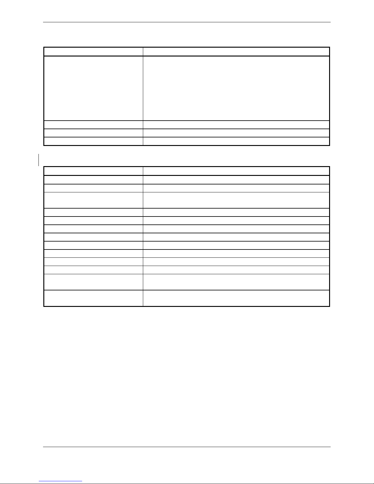
1.4.2 Physical Characteristics
Characteristics Specifications
Modular Rack Width 3.83 inches (9.73 cm)
Modular Rack Height 7.26 inches (18.44 cm)
Standalone Rack Width 3.88 inches (9.86 cm)
Standalone Rack Height 6.91 inches (17.55 cm)
Depth w/connectors (Modular and Standalone) 10.20 inches (25.91 cm)
Unit Weight 5.3 lbs. (2.40 kg)
Modular Rack & Connector Weight* 2.1 lbs. (0.95 kg)
Standalone Rack & Connector Weight* 2.4 lbs. (1.09 kg)
Helicopter Rack Width 3.76 inches (9.55 cm)
Helicopter Rack Height 7.00 inches (17.78 cm)
Depth w/connectors (Helicopter) 10.18 inches (25.86 cm)
Unit Weight (Helicopter) 5.4 lbs (2.45 kg)
Helicopter Rack and Connector Weight* 2.7 lbs (1.22 kg)
*Using 011-01000-01 connector kit. If -00 connector kit is used, add 0.17 lbs (.08 kg).
1.4.3 General Specifications
For detailed specifications, see the Environmental Qualification Form.
Characteristics Specifications
Operating Temperature Range -40°C to +65°C. For more details see Environmental
Qualification Form.
Humidity 95% non-condensing
Altitude Range -1,500 ft to 50,000 ft
DRAFT Rev T 11/12/2010
Page 1-4 GIA 63 Installation Manual
Revision T 190-00303-05
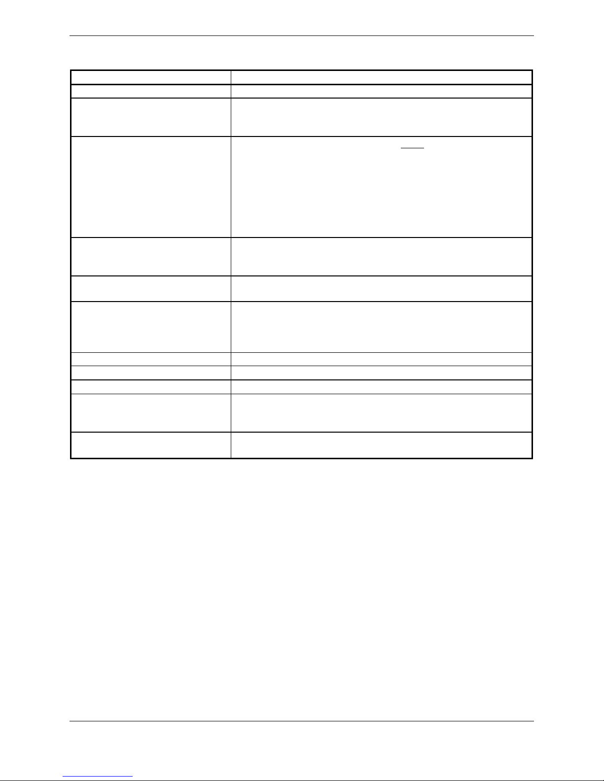
1.4.4 GPS Specifications (GIA 63 only)
Characteristics Specifications
Acquisition Time a) Search-the-Sky (without almanac, without initial position
or time): 5 minutes
b) AutoLocate™(with almanac, without initial position or
time): 5 minutes
c) Cold Start (position known to 300 nm, time known to 10
minutes, with valid almanac): 45 seconds
d) Warm Start (position known to 10 nm, time known to 10
minutes, with valid almanac and ephemeris): 15 seconds
Max Velocity 1000 knots
Dynamics 6 g
Antenna power supply 20 mA typical, 40 mA max at 4.6 VDC
1.4.5 WAAS Specific GPS Specifications (GIA 63W& GIA 63H)
Characteristics Specifications
Number of channels 15 (12 GPS and 3 GPS/WAAS/SBAS)
Frequency 1575.42 MHz L1, C/A code
Sensitivity (acquisition) -116 dBm to -134.5 dBm GPS
-116 dBm to -134.5 dBm WAAS
Sensitivity (drop lock) -144 dBm
Lat/Long position accuracy <1.25 meter RMS horizontal, <2 meter vertical, with WAAS
Velocity 1000 knots maximum (above 60,000 ft)
TTFF (time to first fix) 1:45 min. typical with current almanac, position, and time
Reacquisition 10 seconds typical for signal outages of 30 seconds or less
Position update interval 0.2 sec (5 Hz)
1 pps (pulse per second) ±275 nsec of UTC second during steady-state navigation
Datum WGS-84
SATCOM compatibility Compatible on aircraft equipped with SATCOM (see Section
2.1.3.2 for SATCOM compatible antennas)
Antenna power supply at GPS
port 4.3 VDC to 4.8 VDC @ 60 mA
DRAFT Rev T 11/12/2010

GIA 63 Installation Manual Page 1-5
190-00303-05 Revision T
1.4.6 COM Transceiver Specifications
Characteristics Specifications
Audio Output 100 mW minimum into a 500 Ωload.
Audio Response Less than 6 dB of variation between 350 and 2500 Hz.
Audio Distortion The distortion in the receiver audio output shall not exceed
25% at all levels up to 100 mW.
AGC Characteristics The audio output shall not vary by more than 6 dB when the
level of the RF input signal, modulated 30% at 1000 Hz, is
varied from 5 μV to 100,000 μV (hard).
Sensitivity (S+N)/N on all channels shall be greater than 6 dB when the
RF level is 2 μV (hard) modulated 30% at 1000 Hz at rated
audio.
Squelch 2 μv (hard) ±6 dB for 25 kHz channels.
3 μv (hard) ±6 dB for 8.33 kHz channels.
Selectivity 6 dB BW is greater than ±8 kHz for 25 kHz channeling.
60 dB BW is less than ±25 kHz for 25 kHz channeling.
6 dB BW is greater than ±2.778 kHz for 8.33 kHz
channeling.
60 dB BW is less than ±7.37 kHz for 8.33 kHz channeling.
Spurious Response Greater than 80 dB.
Transmitter Power At Least 16 watts when Vin = 28 VDC
At least 10 watts when Vin = 14 VDC (011-01105-2X and
011-01105-3X only)
Transmitter Duty Cycle Recommended 10% maximum.
Modulation Capability* The modulation shall not be less than 70% and not greater
than 99.9% with a standard modulator signal applied to the
transmitter.
Carrier Noise Level Shall be at least 45 dB (S+N)/N.
Frequency Stability 0.0005%
Demodulated Audio Distortion Less than 10% distortion when the transmitter is modulated
at least 70%.
Sidetone 1.4 VRMS into a 500 Ωload when the transmitter is modulated
at least 70%.
Demodulated Audio Response Shall be less than 6 dB when the audio input frequency is
varied from 350 to 2500 Hz.
*When utilizing the configurable microphone gain adjustments, the modulation capability specification
can be met with a 70 mVrms to 3.0 Vrms analog microphone input signal applied to the transmitter.
When a digital audio microphone signal is provided by a compatible Garmin audio panel, the modulation
capability specification can be met with a minimum 70 mVrms microphone input signal applied to the
audio panel.
DRAFT Rev T 11/12/2010

Page 1-6 GIA 63 Installation Manual
Revision T 190-00303-05
1.4.7 VOR Specifications
Characteristics Specifications
Receiver Audio Sensitivity At -103.5 dBm (S+N)/N shall not be less than 6 dB.
Course Deviation Sensitivity At –103.5 dBm deviation output shall not be less than 60%
of standard deflection (90 mV) when a VOR deviation test
signal is applied (10 degrees course difference).
Flag The VLOC Course Deviation Flag must be flagged:
a) in the absence of an RF signal.
b) in the absence of the 9960 Hz modulation.
c) in the absence of either one of the two 30 Hz
modulations.
d) When the level of a standard VOR deviation test signal
produces less than a 50% of standard deflection.
AGC Characteristics From -99 dBm to -13 dBm input of a Standard VOR Audio
Test Signal, audio output levels shall not vary more than
3 dB.
Spurious Response Greater than 60 dB.
VOR OBS Bearing Accuracy The bearing information as presented to the pilot shall not
have an error in excess of 2.7° as specified by
RTCA DO-196 and EuroCAE ED-22B.
Audio Output A minimum 100 mW into a 500 Ωload.
Audio Response Less than 6 dB of variation between 350 and 2500 Hz. In
voice mode, an ident tone of 1020 Hz shall be attenuated at
least 20 dB.
Audio Distortion The distortion in the receiver audio output shall not exceed
10% at all levels up to 100 mW.
Selectivity 6 dB BW is greater than 16.5 kHz.
DRAFT Rev T 11/12/2010
GIA 63 Installation Manual Page 1-7
190-00303-05 Revision T
1.4.8 LOC Specifications
Characteristics Specifications
Receiver Audio Sensitivity At -103.5 dBm (S+N)/N shall not be less than 6 dB.
Course Deviation Sensitivity At –103.5 dBm, deviation output shall not be less than 60%
of standard deflection when a LOC deviation test signal is
applied.
Flag The VLOC Course Deviation Flag must be flagged:
a) When the level of a standard deviation test signal
produces 50% or less of standard deflection of the deviation
indicator.
b) In the absence of 150 Hz modulation.
c) In the absence of 90 Hz modulation.
d) In the absence of both 90 Hz and 150 Hz modulation.
e) In the absence of RF.
AGC Characteristics From –99 dBm and –13 dBm input of a Standard VOR
Audio Test Signal, audio output levels shall not vary more
than 3 dB.
Selectivity 6 dB BW is greater than 9 kHz.
69 dB BW is less than 36 kHz.
Standard Deflection a) With a standard deflection ‘FLY LEFT’ condition (90 Hz
dominant), the output shall be +90 mV ± 9 mV.
b) With a standard deflection ‘FLY RIGHT’ condition (150 Hz
dominant), the output shall be -90 mV ± 9 mV.
Spurious Response Greater than 60 dB.
Centering Accuracy Typical 0 ±3 mV (Max error 9.9 mV per RTCA DO-195).
Audio Output A minimum 100 mW into a 500 Ωload.
Audio Response Less than 6 dB of Variation between 350 and 2500 Hz. In
voice mode, an ident tone of 1020 Hz shall be attenuated at
least 20 dB.
Audio Distortion The distortion in the receiver audio output shall not exceed
10% at all levels up to 100 mW.
DRAFT Rev T 11/12/2010
Page 1-8 GIA 63 Installation Manual
Revision T 190-00303-05
1.4.9 Glideslope Specifications
Characteristics Specifications
Sensitivity At –93 dBm, deviation output shall not be less than 60% of
standard deflection when glideslope deviation test signal is
applied.
Centering Accuracy 0 ±.0091 ddm or 0 ±7.8 mV.
Selectivity 6 dB BW is greater than 17 kHz.
69 dB BW is less than 132 kHz.
Standard deflection a) With a standard deflection ‘FLY DOWN’ condition (90 Hz
dominant), the output shall be -78 mV ± 7.8 mV.
b) With a standard deflection ‘FLY UP’ condition (150 Hz
dominant), the output shall be +78 mV ± 7.8 mV.
Flag The GS Course Deviation Flag must be flagged:
a) When the level of a standard deviation test signal
produces 50% or less of standard deflection of the
deviation indicator.
b) In the absence of 150 Hz modulation.
c) In the absence of 90 Hz modulation.
d) In the absence of both 90 Hz and 150 Hz modulation.
e) In the absence of RF.
1.4.10 Power Requirements
Characteristics Specifications
Input Voltage Range 28 Vdc for P601 (14/28 Vdc for 011-01105-20 and
011-01105-30 units)
14/28 Vdc for P605
See the Environmental Qualification Form for details on
surge ratings and minimum/maximum operating voltages.
Power Requirements for P601
(COM Connector)
0.3 A max @ 27.5 Vdc (not transmitting);
4.3 A max @ 27.5 Vdc (transmitting)
011-01105-20,
011-01105-30 units
Power Requirements for P601
(COM Connector)
0.6 A max @ 13.75 Vdc (not transmitting);
6.0 A max @ 13.75 Vdc (transmitting)
Superflag Power
Requirements for P605
(Main 2 Connector)
Power depends upon loads present on Superflag output pins
(see Sections 4.7.2.1 and 4.10.7)
Power Requirements for P605
(Main 2 Connector)
1.0 A max @ 27.5 Vdc (Without Superflags Active)
2.0 A max @ 13.75 Vdc (Without Superflags Active)
DRAFT Rev T 11/12/2010
GIA 63 Installation Manual Page 1-9
190-00303-05 Revision T
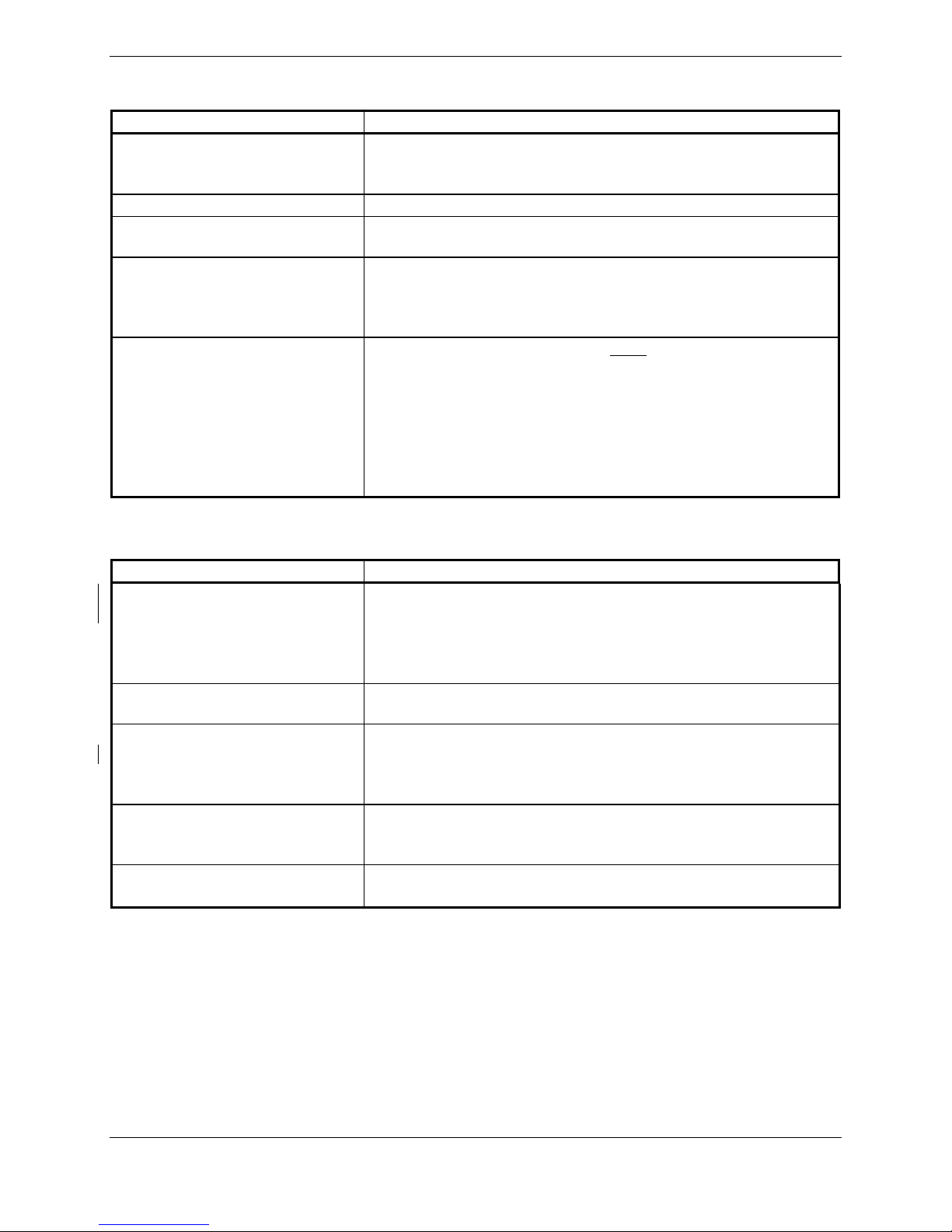
1.4.11 Power Interrupt
Unit Name Unit Part Number Mod
Status*
Long Term Power
Interrupt Category
Per RTCA DO-160D**
4 A (200mS)
011-00781-00 0, 1, 2, 3 B (50mS)
1 A (200mS)
GIA 63
011-00781-01 0 B (50mS)
1 A (200mS)
011-01105-00 0 B (50mS)
011-01105-01 0 A (200mS)
GIA 63W
011-01105-20 0 A (200mS)
GIA 63H 011-01105-30 0 A (200mS)
* Refer to Mod Status Table in front of manual for applicable mod levels.
** Refer to the Section 3.8 for Continued Airworthiness.
1.5 License Requirements
The Telecommunications Act of 1996, effective February 8, 1996, provides the FCC discretion to
eliminate radio station license requirements for aircraft and ships. The GIA 63(X) installation must
comply with current transmitter licensing requirements. To find out the specific details on whether a
particular installation is exempt from licensing, please visit the FCC web site
http://wireless.fcc.gov/aviation.
Transmitter Description: Aviation-band VHF transceiver with 25 and 8.33 kHz channel spacing.
Antenna Characteristics: Broad band, 50 ohm, vertically polarized.
Rated Power: 16 Watts (28 VDC Operation)
10 Watts (14 VDC Operation; 011-01105-2X and -3X only)
Emission Type: 6K00A3E (25 kHz Channel Spacing Mode)
5K6A3E (8.33 kHz Channel Spacing Mode; 011-01105-2X and
-3X only)
Frequency of Operation: 118.00 – 136.992 MHz
If an aircraft license is required, make application for a license on FCC form 404, application for Aircraft
Radio Station License. The FCC also has a fax-on-demand service to provide forms by fax. The
GIA 63(X) owner accepts all responsibility for obtaining the proper licensing before using the transmitter.
International transmitter license procedures vary by country. Contact the local spectrum agency for
license requirements.
CAUTION
The VHF transmitter in this equipment is guaranteed to meet federal communications
commission acceptance over the operating temperature range. Modifications not
expressly approved by Garmin could invalidate the license and make it unlawful to
operate the equipment.
DRAFT Rev T 11/12/2010

Page 1-10 GIA 63 Installation Manual
Revision T 190-00303-05
1.6 Certification
The GIA 63 GPS receiver is certified for IFR enroute, terminal, and non-precision approaches. The
GIA 63W and the GIA 63H GPS receivers are WAAS certified.
The GIA 63(X) has been qualified to RTCA/DO-160 Section 20 RF susceptibility and Section 22
lightning requirements. Special installation considerations are required, refer to the Environmental
Qualification Form.
The GIA 63(X) meets the requirements for GPS as a Primary Means of Navigation for Oceanic/Remote
Operations per FAA Notice N8110.60.
The GIA 63(X) is eligible for B-RNAV in accordance with AMC 20-4.
Eligible for PRNAV in accordance with PRNAV requirements: JAA Administrative & Guidance
Material Section One: General Part 3: Temporary Guidance Leaflets, Leaflet No 10: Airworthiness and
Operational Approval for Precession RNAV Operations in Designated European Airspace 7.1 Required
Functions.
The conditions and tests required for TSO approval of this article are minimum performance standards. It
is the responsibility of those installing this article either on or within a specific type or class of aircraft to
determine that the aircraft installation conditions are within the TSO standards. TSO articles must have
separate approval for installation in an aircraft. The article may be installed only if performed under 14
CFR part 43 or the applicable airworthiness requirements. At the time of publication, installations of this
TSO approved article are only approved when installed in an aircraft as part of a Garmin Integrated Flight
Deck.
The quantitative safety objective for the VHF Comm radio in the GIA 63W and the GIA 63H is 1 X 10⁻⁴
per flight hour for Class I Part 23 Airplanes, and 1 X 10⁻⁵ per flight hour for all other Part 23 airplanes
and Parts 25, 27, and 29 aircraft.
DRAFT Rev T 11/12/2010
GIA 63 Installation Manual Page 1-11
190-00303-05 Revision T
1.6.1 GIA 63 TSO/ETSO Compliance
Function TSO/ETSO Category
Applicable LRU SW Part
Numbers
Applicable CLD
Part Numbers
006-C0046-()
006-C0044-()
006-C0047-()
Automatic Pilots TSO-C9c
ETSO-C9c
All
006-B0190-()
except
006-B0190-00
through
006-B0190-19 006-C0039-01
006-C0046-()
006-C0044-()
006-C0047-()
Glideslope
Receiver
TSO-C34e
ETSO-2C34f
All
006-B0190-()
except
006-B0190-00
through
006-B0190-04
006-B0083-01
006-C0039-01
006-C0046-()
006-C0044-()
006-C0047-()
006-C0039-01
Localizer Receiver TSO-C36e
ETSO-2C36f Class A
All
006-B0190-()
except
006-B0190-00
through
006-B0190-04
006-B0082-02
006-C0053-00
006-C0046-()
006-C0044-()
VHF COM
Transmitter
TSO-C37d
ETSO-2C37e Class 3 and 5
006-C0047-()
VHF COM
Receiver
TSO-C38d
ETSO-2C38e Class C and E
All
006-B0190-()
except
006-B0190-00
through
006-B0190-04
All
006-B0081-0()
except
006-B0081-00
through
006-B0081-04 006-C0039-01
006-C0046-()
006-C0044-()
006-C0047-()
006-C0039-01
VOR Receiver TSO-C40c
ETSO-2C40c
All
006-B0190-()
except
006-B0190-00
through
006-B0190-04
006-B0082-02
006-C0053-00
006-C0046-()
006-C0044-()
006-C0047-()
Flight Director
Equipment
TSO-C52b
ETSO-C52b
All
006-B0190-()
except
006-B0190-00
through
006-B0190-19 006-C0039-01
006-C0046-()
006-C0044-()
006-C0047-()
Ground Proximity
Warning – Glide
Slope Deviation
Alerting
Equipment
TSO-C92c
All
006-B0190-()
except
006-B0190-00
through
006-B0190-29 006-C0039-01
006-C0046-()
006-C0044-()
GPS TSO-C129a
ETSO-C129a Class A1
All
006-B0190-()
except
006-B0190-00
through
006-B0190-04
006-B0093-00
006-B0093-01
006-C0047-()
006-C0046-()
TSO-C151b Class A and B 006-C0044-()
006-C0047-()
TAWS
ETSO-C151a Class B
All
006-B0190-()
except
006-B0190-00
through
006-B0190-29 006-C0039-01
DRAFT Rev T 11/12/2010

Page 1-12 GIA 63 Installation Manual
Revision T 190-00303-05
1.6.2 GIA 63 TSO/ETSO Deviations
TSO/ETSO Deviation
1. Garmin was granted a deviation from TSO-C9c to use SAE AS 402B instead of AS-
402A.
2. Garmin was granted a deviation from TSO-C9c to use DO-160D instead of specified
environmental tests.
3. Garmin was granted a deviation from TSO-C9c subpart A (c), which requires marking
the weight of the unit on the unit. Garmin will provide this information in the installation
manual in lieu of marking on the serial tag. Garmin does not currently list the weight on
other avionics units.
4. Garmin was granted a deviation from SAE AS 402B paragraph 4.4.1 to limit autopilot
engagement to attitudes considered safe for the certified aircraft.
TSO-C9c
5. Garmin was granted a deviation from SAE AS 402B paragraph 4.3.2 to not provide
servo effort indications when the automatic pilot is not engaged.
1. Garmin was granted a deviation from ETSO-C9c to use SAE AS-402B instead of AS-
402A.
2. Garmin was granted a deviation from ETSO-C9c to use DO-160D instead of the
specified environmental tests.
3. Garmin was granted a deviation from AS-402B paragraph 4.3.2 to not provide servo
effort indications when the automatic pilot is not engaged.
ETSO-C9c
4. Garmin was granted a deviation from AS-402B paragraph 4.4.1 to limit autopilot
engagement to attitudes considered safe for the certified aircraft.
TSO-C34e 1. Garmin was granted a deviation from TSO-C34e to use DO-160D Change 3 instead of
DO-160B, and DO-178B instead of DO-178A.
TSO-C36e 1. Garmin was granted a deviation from TSO-C36e to use DO-160D Change 3 instead of
DO-160B, and DO-178B instead of DO-178A.
1. Garmin was granted a deviation from TSO-C37d to use DO-160D Change 3 instead of
DO-160B, and DO-178B instead of DO-178A.
2. Garmin was granted a deviation from TSO-C37d paragraph (a)(1) to allow using RTCA
document DO-186a Change 2 instead of RTCA document DO-186 to specify minimum
performance standards.
3. Garmin was granted a deviation from TSO-C37d by allowing a 6dB reduction of
transmitter power during the Normal Operating Conditions - Emergency Operation Voltage
as described in RTCA document DO-186a paragraph 2.5.13.1 and RTCA document DO-
160C paragraph 16.5.2.1.
4. Garmin was granted a deviation from TSO-C37d paragraph (a)(5) to allow 8.33 kHz
spacing in addition to the 25 kHz spacing.
TSO-C37d
5. Garmin was granted a deviation from TSO-C37d paragraph (b)(1) to allow the marking
to call out 8.33 kHz spacing in addition to the 25 kHz spacing.
1. Garmin was granted a deviation from TSO-C38d to use DO-160D Change 3 instead of
DO-160B, and DO-178B instead of DO-178A.
2. Garmin was granted a deviation from TSO-C38d paragraph (a)(1) to allow using RTCA
document DO-186a Change 2 instead of RTCA document DO-186 to specify minimum
performance standards.
TSO-C38d
3. Garmin was granted a deviation from TSO-C38d paragraph (a)(5) to allow 8.33 kHz
spacing in addition to the 25 kHz spacing.
TSO-C40c 1. Garmin was granted a deviation from TSO-C40c to use DO-160D Change 3 instead of
DO-160B, and DO-178B instead of DO-178A.
1. Garmin was granted a deviation from SAE AS 8008 paragraph 3.6 to limit flight director
operation to attitudes considered safe for the certified aircraft.
TSO-C52b
2. Garmin was granted a deviation from TSO-C52b to use DO-160D instead of DO-160C.
ETSO-C52b 1. Garmin was granted a deviation from AS-8008 paragraph 3.6 to limit flight director
operation to attitudes considered safe for the certified aircraft.
DRAFT Rev T 11/12/2010
Other manuals for GIA 63
2
Table of contents
Other Garmin Control Unit manuals


Popular Control Unit manuals by other brands

Intermatic
Intermatic K4000 series Instructions for installing

Okina
Okina OK-PTZ-KB250X user manual

BARTEC FEAM
BARTEC FEAM SAnA Series Instructions for use

bihl+Wiedemann
bihl+Wiedemann BW3489 installation instructions

gefran
gefran GFW adv Series INSTRUCTION MANUAL FOR CONFIGURATION AND INSTALLATION

Source fire
Source fire DC750 quick start guide


