Garmin Fusion EL Series User manual

EL SERIES SPEAKERS
INSTALLATION INSTRUCTIONS
Important Safety Information
WARNING
See the Important Safety and Product Information guide in the product box for product warnings and other
important information.
This device must be installed according to these instructions.
Disconnect the vessel's power supply before beginning to install this device.
CAUTION
Continuous exposure to sound pressure levels over 100dBA may cause permanent hearing loss. The volume
is typically too loud if you cannot hear people speaking around you. Limit the amount of time you listen at high
volume. If you experience ringing in your ears or muffled speech, stop listening and have your hearing checked.
To avoid possible personal injury, always wear safety goggles, ear protection, and a dust mask when drilling,
cutting, or sanding.
NOTICE
When drilling or cutting, always check what is on the opposite side of the surface to avoid damaging the vessel.
It is strongly recommended that you have your audio system installed by a professional installer to ensure
optimum performance.
You must read all installation instructions before beginning the installation. If you experience difficulty during
the installation, go to support.garmin.com for product support.
After installing an audio system, you should run the connected speakers and subwoofers at low to medium
volumes for the first few hours of use. This helps to improve the overall sound by gradually loosening up the
moving components of new speakers and subwoofers, such as the cone, spider, and surround.
GUID-FF67D738-0427-418B-829A-44F0C22D890C v4September 2022

Tools Needed
• Electric drill
• Drill bit (size varies based on surface material)
• Appropriate saw or utility knife to cut surface material
• Phillips screwdriver
• Wire strippers
• 16 AWG (1.3 through 1.5mm2) marine-grade, fully-tinned copper speaker wire
You can purchase this wire from your Fusion® or Garmin® dealer:
◦010-12899-00: 7.62m (25ft.)
◦010-12899-10: 15.24m (50ft.)
◦010-12899-20: 100m (328 ft.)
• 6.3mm and 4.8mm female spade connectors (recommended)
• 20AWG (0.5 through 0.75mm2) marine-grade, fully-tinned copper wire for the RGB LED connections (LED
models only).
• 4 mm male and female bullet connectors for the LED wires (recommended, LED models only)
• Crimping tool
• Marine sealant (optional)
NOTE: For customized installations, additional tools and materials may be needed.
Mounting Considerations
NOTICE
When mounting the speaker in an area exposed to weather or water, you must mount the speaker on a vertical
surface. If you mount the speaker on a horizontal surface facing up, water can gather in and around the speaker,
causing damage over time.
If you intend to mount the speakers outside the boat, you must mount them in a location well above the
waterline, where they are not submerged or damaged by docks, pilings, or other pieces of equipment. When
mounted correctly, these speakers are rated for protection from the front of the speaker. Water exposure and
damage to the rear of the speaker voids the warranty. This includes situations when the speakers are mounted
in a sealed enclosure, especially if they are exposed to wash down. Using an enclosure with a port or vent
exposed to the outside environment may allow water to collect and damage the speaker.
You must turn off the audio system before making any connections to the source unit, amplifier, or speakers.
Failure to do so could result in permanent damage to the audio system.
You should protect all terminals and connections from grounding and from each other. Failure to do so could
result in permanent damage to the audio system and void the product warranty.
When selecting a mounting location for the speakers, observe these considerations:
• You must select mounting locations that provide sufficient clearance for the mounting depth of the speakers
as specified in the product specifications.
• You should select a flat mounting surface for the best seal.
• You should protect the speaker wires from sharp objects and always use rubber grommets when wiring
through panels.
• To avoid interference with a magnetic compass, you should not mount the speakers closer to a compass
than the compass-safe distance value listed in the product specifications.
Selecting the correct mounting location optimizes the performance of each speaker. Fusion speakers are
designed to perform in the widest possible range of mounting locations, but the more you plan the installation,
the better the speakers' sound will be. For more information on speaker placement and specifications, go to
garmin.com.
2
Mounting the Speakers
Before mounting the speakers, you must choose a location following the guidelines above.
Before cutting the mounting surface you should verify that there is enough clearance for the speaker behind the
surface. Refer to the specifications for clearance information.
NOTICE
Do not apply grease or lubricant to the screws when fastening the speakers to the mounting surface. Grease or
other lubricants can cause damage to the speaker.
1Route the wires from the source to the speaker location, away from sources of electrical interference.
2Trim the template and make sure it fits in the selected location.
3Orient the template so that the Fusion logo is right-side up on the template.
4Secure the template to the selected location.
5Using a rotary tool or jigsaw, cut the mounting surface along the inside of the line on the template.
6Place the speaker in the cutout to test the fit.
7If necessary, use a file and sandpaper to refine the size of the cutout.
8After the speaker fits correctly in the cutout, ensure the mounting holes on the speaker line up with the pilot
holes on the template.
9If the mounting holes on the speaker do not line up, mark the new hole locations.
10 Using an appropriately sized drill bit for the mounting surface and screw type, drill the holes.
11 Remove the template from the mounting surface.
12 Connect the speaker wires while observing polarity (Speaker Wiring, page4).
13 If necessary, connect the LED wires (LED Wiring, page4).
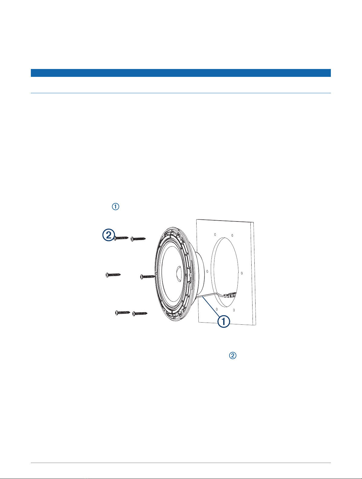
14 Place the speaker in the cutout.
15 Secure the speaker to the mounting surface using the included screws .
NOTE: Do not over tighten the screws, especially if the mounting surface is not flat.
16 With the speakers mounted, hold the grille with the Fusion logo at the bottom, or at the 6 o'clock position.
17 Turn the grille counter-clockwise about 30 degrees, so the Fusion logo is at the 5 o'clock position.
18 Place the grille on the speaker, and twist it clockwise to secure it.
NOTE: Instead of twisting to install the grille, you can line it up so the Fusion logo is at the 6 o'clock position
and press to snap it into place.
3

Speaker Wiring
When connecting the speakers to your stereo, observe these considerations.
• Speaker wire is not included with the speakers. You should use 16AWG (1.3 through 1.5mm2) speaker wire
to connect the speakers to the stereo.
• The leads on the speakers are terminated using male spade connectors. You should use female spade
connectors (not included) to connect the speaker wire to the speaker leads for the best connection.
• You can use this table to identify the polarity and spade-connector sizes of the leads on the speaker.
Speaker wire color Speaker wire polarity Spade connector size
White Positive (+) 6.3mm
White with a black stripe Negative (-) 4.8mm
LED Wiring
NOTICE
Using certain LED colors on the speakers, such as red and green, may violate the laws, regulations, and
standards related to the use and/or operation of marine navigation lights. It is the user's responsibility to
comply with any such applicable laws, regulations, and standards. Garmin is not responsible for any fines,
penalties, citations, or damages that may be incurred due to any such lack of compliance.
It is recommended to install a Fusion RGB Wireless Remote Control module with these speakers to turn the
LEDs on and off, change the colors, and create lighting effects. See your Fusion dealer or garmin.com for more
information.
You should follow the instructions provided with the RGB Wireless Remote Control to connect the LED wires
from the speakers to the remote control receiver module and to connect the receiver to power.
If you choose not to install the remote control, you can set the static color of the LEDs by connecting
combinations of the LED wires directly to the power source (Connecting the LED Wires, page5).
4

Connecting the LED Wires
If you choose to not install a remote control to turn the LEDs on and off, change the color, and create lighting
effects, you can choose a static LED color by connecting specific LED color wires to ground. You can splice the
ground wire to a combination of LED wires to customize the LED color beyond red, green, or blue.
NOTE: LEDs are not available on all models.
The black wire on the LED cable is terminated with a 4mm female bullet connector, and the color wires are
terminated with 4mm male bullet connectors. You can connect these to 4mm bullet connectors on your wires
(not included), or remove the bullet connectors to connect to the bare wires instead.
1Connect a positive wire to the black wire on the LED cable.
2Connect a ground wire to the wire or the combination of wires on the LED cable according to the preferred
LED color.
LED Color LED Wire Color
Red Red wire
Green Green wire
Blue Blue wire
Yellow Combined red and green wires
Magenta Combined red and blue wires
Cyan Combined blue and green wires
White Combined red, green, and blue wires
3Route the positive and negative wires, and connect them to a power source (Connecting the LED Wires to
Power, page5).
Connecting the LED Wires to Power
NOTE: LEDs are not available on all models.
You must connect all 12Vdc wiring to the LEDs to a 3A fuse at the power-source end of the cable. You should
connect the positive (+) power wire to a 12Vdc power source through an isolator switch or circuit breaker to
turn the LEDs on and off. You can use the same isolator or circuit breaker controlling the power supply to your
stereo, which allows you to turn the LEDs and the stereo on and off at the same time.
You should use 20AWG (0.5 through .75mm2) or thicker wire to connect the LEDs to the battery.
1Route the positive power (+) and negative ground (-) wires from the LED-wire connections to the battery.
2Connect the negative wire to the negative (-) battery terminal.
3Connect the positive wire to the positive (+) terminal through a 3A fuse and isolator switch or circuit breaker.
Speaker Information
Registering Your Fusion Device
Help us better support you by completing our online registration today.
• Go to garmin.com.
• Keep the original sales receipt, or a photocopy, in a safe place.
5

Dimension Drawings
Side View
40mm (137/64in.)
127mm (5in.)
A Sports model speaker is shown, but the dimensions are the same for the Classic model.
Front View
176mm (615/16in.)
A Sports model speaker is shown, but the dimensions are the same for the Classic model.
6

Back View
176mm (615/16in.)
156mm (61/8in.)
Cleaning the Speakers
NOTE: When mounted correctly, these speakers are rated IP65 for dust and water ingress protection under
normal conditions. They are not designed to withstand high pressure water spray, which may occur when
you wash down your vessel. Failure to carefully spray-clean the vessel may damage the product and void the
warranty.
NOTICE
Do not use harsh or solvent-based cleaners on the speakers. Using such cleaners may damage the product and
void the warranty.
1Clean all salt water and salt residue from the speaker with a damp cloth soaked in fresh water.
2Use a mild detergent to remove a heavy buildup of salt or stains.
Troubleshooting
Before you contact your Fusion dealer or service center, you should perform a few simple troubleshooting steps
to help diagnose the problem.
If the Fusion speaker has been installed by a professional installation company, you should contact the
company so the technicians can assess the problem and advise you about possible solutions.
There is no sound coming from the speakers
• Verify that all connections from the source device and/or the amplifier are connected correctly to the speaker
terminals.
The system lacks bass or high frequencies
• Verify that the correct wire polarity is observed between the source and speakers.
The wires should be connected positive to positive and negative to negative.
• Verify that the speakers are attached firmly to the mounting surface.
7

The audio is distorted
• Verify that the source volume is not too loud for the speaker, and reduce the volume if necessary.
• Verify that the panels surrounding the speaker on the vessel are not rattling.
• Verify that the source device and/or the amplifier are connected to the speaker terminals correctly.
• If the speaker is connected to an amplifier, verify that the input level of the amplifier is matched to the output
level of the stereo. For more information, see the manual for the amplifier.
The LED lights will not turn on
• Verify that all wiring connections are correct and tight.
Specifications
Max. power (Watts) 80W
RMS power (Watts) 20W
Efficiency (1W/1m) 88dB
Frequency response (+3dB) 45Hz to 16kHz
Min. mounting depth (clearance) 43mm (1 11/16in.)
Mounting diameter (clearance) 130mm (51/8in.)
Impedance 4ohm
Amplifier power-rating recommendation From 20 to 40W RMS, playing music
LED supply voltage (sports model speakers only) From 10.8 to 16 Vdc
LED load current at 16Vdc (sports model speakers only) 150mA per color
Optimum enclosure volume recommendation18L (0.3ft.3)
Operating temperature range From 0 to 50°C (from 32 to 122°F)
Storage temperature range From -20 to 70°C (from -4 to 158°F)
Cone material Polypropylene
Water and dust rating IEC 60529 IP65
NOTE: This speaker is not intended to be installed in a vented or ported enclosure.
1 Sealed enclosure, fully filled with absorption material.
8

Compass-Safe Distances
All speakers contain magnets which may cause interference with instruments on your boat. The size of the
magnet used in the speaker affects how much interference the speaker may cause.
Interference can cause deviations and variations in the readings of sensitive navigational equipment, such as
magnetic compasses. These deviations can cause inaccuracies or offsets in the readings, but will not harm
the equipment. To alleviate the deviations, adjust the compass for the deviation following the manufacturer's
instructions or move the speaker away from the navigational equipment. After moving a source of interference,
you may need to recalibrate the compass.
If you are navigating solely by a magnetic compass, use extreme caution to place the speaker far enough away
from the compass to avoid causing deviations in the readings.
To avoid deviations to navigational equipment, position the speakers so they are separated from the
navigational equipment by at least the distance listed in the table below.
171cm (5ft. 8in.)
171cm (5ft. 8in.)
254cm (8ft 4in.)
171cm (5ft. 8in.)
171cm (5ft. 8in.)
254cm (8ft 4in.)
© 2018 Garmin Ltd. or its subsidiaries
Garmin®, the Garmin logo, Fusion®, and the Fusion logo are trademarks of Garmin Ltd. or its subsidiaries, registered in the USA and other countries. These trademarks
may not be used without the express permission of Garmin.
9

© 2018 Garmin Ltd. or its subsidiaries support.garmin.com
Table of contents
Other Garmin Speakers manuals


