Garnet 4G-MAX-G User guide

EN ENGLISH 4G-MAX-G www.garnet.com.ar
WIFI / 4G / 3G / 2G
COMMUNICATOR
Installer's Manual
2 3
General Information ......................................................................................................
Technical Specications ................................................................................................
Description of the Module ............................................................................................
Connections ....................................................................................................................
Status light indications ..................................................................................................
Communicator / Alarm Panel Programming ..............................................................
Programming the Communicator and Panels from the Garnet Programmer App
Enabling telephones Garnet panels.............................................................................
Enabling telephones DSC panels .................................................................................
Programming Videos .....................................................................................................
Communicator Reset ....................................................................................................
Remote Control with 4G-MAX-G/IP-500G Communicators ......................................
Notes ...............................................................................................................................
Guarantee.........................................................................................................................
3
3
4
5
7
8
9
10
12
13
13
14
16
17
Page
INDEX Information General
The 4G-MAX-G communicator is designed to report events via three communica-
tion paths:
1) Internet connection via a Wi network
2) Internet connection using mobile data service
3) Sending text messages using the cellular service (SMS)
In residential reports, the communicator prioritises communications through a
Wi-Fi connection, therefore, the mobile phone connection or data transmission is
used as a backup in the event of a failure or absence of the Wi-Fi network connec-
tion.
When reporting to monitoring, communications are organised through the com-
munication scenarios.
Specications Technical:
WiFi:
• Transmission: Wi-Fi certied 2.4Ghz, IEEE 802.11.
• FCC/CE-RED/IC/TELEC/KCC/SRRC/NCC certicate
• Transmitting power: 20.5 dBm.
• Wi-Fi authentication via WEP, WPA-PSK and WPA2-PSK.
• Antenna: PCB trace type.
Mobile data module:
• Transmission: LTE, UMTS/HSPA+ and GSM/GPRS/EDGE.
• Carrier conguration: Automatic.
General specications
• Two-way WiFi and 4G LTE communication, UMTS/HSPA+ and GSM/GPRS/EDGE
• Compatible with PC-732G / PC-860 / PC-800.
• 1 mobile network recipient and 1 WiFi recipient for monitoring reports
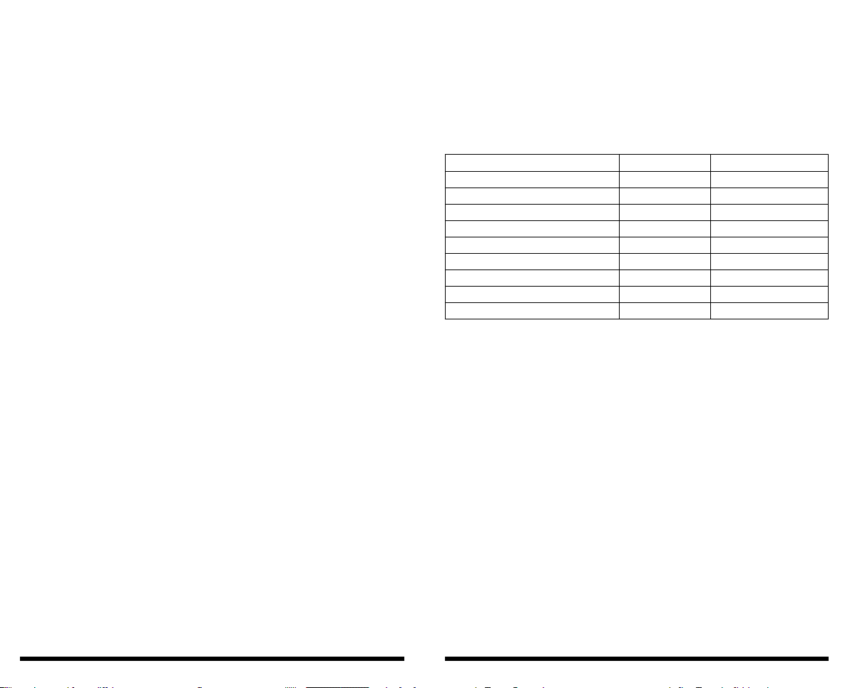
LTE Cat 4
Región/Operador
Dimensiones (mm)
Rango de temperatura
Banda de frecuencia
Australia, Nueva Zelanda, Latinoamérica
LTE-FDD B1/B2/B3/B4/B5/B7/B8/B28/B66
LTE-TDD B40
WCDMA B1/B2/B4/B5/B8
GSM/EDGE B2/B3/B5/B8
GNSS* -
29.0 x 32.0 x 2.4
Rango de temperatura de funcionamiento
Rango de temperatura extendido
-35 °C a +75 °C
-40 °C a +85 °C
EC200A-AU

4 5
• Allows for own and panel programming with AC4 software
• Allows local and remote programming from Garnet Programmer
• Reports with residential format (event restriction).
• You can use domain names instead of IP addresses.
• Connection with dedicated bus (BUS-C485).
• Allows remote operation of the system via smartphones using the Garnet Control
App.
• Communication of Reports using UDP.
• Up to 20 residential users.
• WiFi monitoring period congurable from 1 to 99 minutes.
• Monitoring period for mobile data congurable from 1 to 9999 minutes.
• Two Garnet reporting formats: DC1 and SDC2.
• 9 LED status and signal indicators on the board.
• Does not require its own battery, it shares the battery of the alarm panel.
• Nominal supply voltage: 12VDC (9 to 14VDC).
• Power consumption: 90 ~ 135 mA
Description of the module:
Communication formats:
The 4G-MAX-G Alarm Communicator is designed to send alarm signals and status
to monitoring stations receiving events under the DC1 and SDC2 communication
protocols.
Panel control modes:
The 4G-MAX-G communicator allows control of the panels via two methods, one
method is by using the Garnet Control application, and the other method is via
text messages or SMS.
Compatible panels:
The 4G-MAX-G communicator is compatible with the Garnet and DSC panel
families.
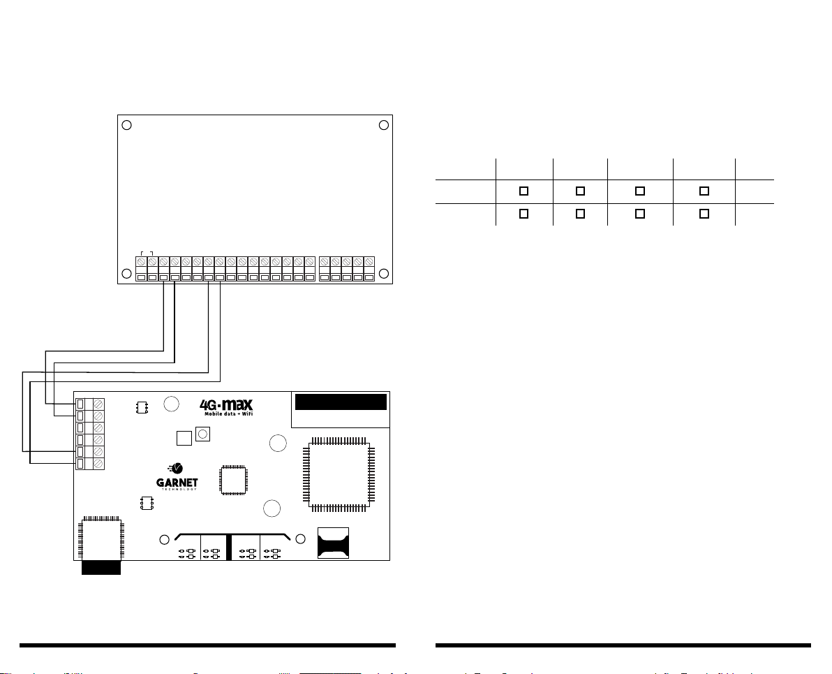
For Garnet panels, the communicator must be installed on the BUS-C485 data bus
(see gure 1), while for DSC panels, the communicator must be installed on the
keypad data bus.
(See gure 2).
Compatible Garnet panel models:
PC-732G / PC-860 / PC-800
Models compatible with DSC panels:
PC585, PC1565, PC832, PC1832, PC5015, PC.5010, PC161616
Connections:
Figure 1 - BUS-C485 mode of operation:
- AUX + + BELL - A B
PGM1 PGM2
Z1 Z6CZ5Z4CZ3Z2C R1 TIP
RING
T1
AC + BAT - A B+ AUX -
+ A B Y G-
ANTENA
WIFI
SIGNAL 1-5
NO SIGNAL
ANTENA
DAT OS
COMUNIC
WIFI
COMUNIC
DAT OS
ACK
NAK
6 7
Figure 2 - DSC mode of operation:
AC - AUX + + BELL - 1 PGM 2
KEY PAD
YEL GRN Z1 Z2
COM Z3 Z4
COM RNG T-1 EGND
R-1
TIP
PANEL DSC
+ A B Y G-
ANTENA
WIFI
SIGNAL 1-5
NO SIGNAL
ANTENA
DAT OS
COMUNIC
WIFI
COMUNIC
DAT OS
ACK
NAK
Light indications of states
The 4G-MAX-G communicator incorporates a variety of LEDs to indicate dierent
communicator statuses.
LEDs indicate the signal strength of the Wi-Fi network, the Mobile Data network
and the results of the reports to the server and the monitoring station.
Explanation of light indications:
There are two groups of leds, the ones that inform the signal strength of the Wi
or Data connection and the ones that inform the results of the Wi and data com-
munications in the mobile network.
Wi Signal or Mobile Data Network Indicator LEDs
These LEDs indicate whether or not the communicator is connected to a network.
If the communicator is connected to a Wi network, the blue LED representing the
Wi Antenna will indicate its signal strength by ashing as many times as its signal
level.
The number of ashes represents the signal level, with 1 ash for a very low signal
level and 5 ashes to indicate the maximum signal level.
If the communicator is not connected to a Wi network, the red “No Signal” LED
will be on indicating that the communicator is not connected to a Wi network.
The same behavioural pattern is repeated for mobile data antenna indications.
Communication indicator LEDs
The communicator is prepared to communicate through a Wi connection or
through mobile data. In either case, when there is a communication or any kind of
report, its result will be indicated by the leds that represent the communications.
Wi Antenna Data Antenna Comunic Wi Comunic Data
Signal 1-5
No Signal
ACK
NAK
8 9
When a report is made to the monitoring station or in residential format, the re-
sult will be represented by two LEDs, one representing the successful report (ACK)
or the one indicating communication failure (NAK).
When the communicator reports a supervision to monitoring or to the server, it
will light both LEDs simultaneously.
Status LED
This LED indicates the working mode according to the ashing speed.
If the led ashes slowly (1 time per second), it means that it is congured to work
in “DSC” mode, if the ashing is fast (10 times per second), it is congured to work
in the BUS-C485.
NET” LED
This LED indicates the status of the mobile data network.
State
Communicator programming / Alarm panels
Programming of the alarm panel:
In order to congure the Garnet alarm panels via the communicator, the commu-
nicator must rst be enabled in the panels. To do this, the following steps must be
carried out in panel programming:
With Keyboard G-LCD732 / G-LCD732RF / KPD-860 / KPD-860RF
1) Tool key + [5] + [INSTALLER CODE].
2) Program the command [299] with the following values [xxxx11xx].
With Keyboard G-LED732 / KPD-800
1) *8 + [5] + [INSTALLER CODE] + [INSTALLER CODE].
2) Program the command [299] with the following values [xxxx11xx].
NOTE: DSC panels cannot be programmed via the communicator and the
conguration App.
200 mS on / 1800 mS o 1800 mS on / Seeking Idle
Network
Transferring data
1800 mS encendido / 200 mS apagado
200 mS o 125 mS on / 125 mS o
Description
Programming the Communicator and Panel from the Gar-
net Programmer app
The communicator is programmed via the “Garnet Programmer” app. This app
also allows the Garnet alarm panels to be programmed.
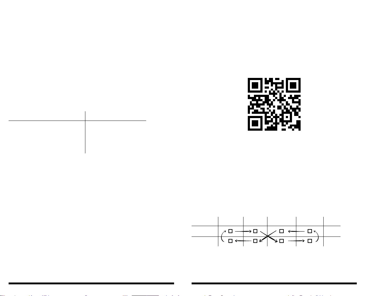
To download the scheduling app, scan the following QR codes as appropriate or
search the download shop for the
Garnet Programmer application
Follow the steps below:
1) Press the “AP ENABLE” button on the nameplate.
This will cause the communicator to generate a WiFi network for a period of 5
minutes.
2) Search your phone for available WiFi networks and connect to the WiFi network
whose name is “4G-MAX-Gxxxxxx”. XXXXXX being the last 6 digits of the communi-
cator mac.
3) Enter the default network password: admin1234.
4) Once the communicator enters programming mode.
The LEDs will behave as follows
If this result is not achieved. Repeat the steps from the beginning.
It is essential that the mobile phone is in “Airplane” mode when
connecting to the module’s WiFi network.
Antenna Wi Antena Data Comunic Wi Comunic Data
Signal 1-5
No Signal
ACK
NAK
Download App
Click here
10 11
5) Once ready, open the Garnet Programmer application and follow the instruc-
tions you wish to program.
Note: In programming the communicator within the “status” screen you should
make a note of the System Number as it will be used in the next step.
Enabling Telephones or Terminals
To enable the phones, you must rst ensure that the communicator was pre-
viously congured and has a successful connection to the internet through a Wi
connection or by using mobile data.
From your phone shop download the “Garnet Control” User application.
Once you have downloaded the application, you must register using your personal
data.
Then within the application press the “+” button to add a new system, you must
enter the System Number obtained in the previous step, a name that identies the
alarm system that is installed and nally an icon.
You must then initiate the connection to your phone from the communicator. You
will need to press the “AP ENABLED” button 3 times in a row, or if you have an LCD
keypad press [ ] + 8 + 7.
Conrmation of successful enablement will be by ashing the top 4 antenna and
communications indication LEDs. After this press the “Verify” button on your
mobile phone.
In seconds your application will be ready for use.
Note: The Garnet Control application allows up to 20 total users to be associated.
Download App
Click here
The main user that was associated will be listed as “Administrator”. This user will
be able to invite the remaining 19 users of the system with two dierent user
categories:
• Main User:
This user can be dened by the administrator in terms of the functions and per-
missions he/she has over the alarm panel.
For example: You can have a user as a family member who has all the functions
of remote control and event reception checked. But I can also have a main user
that only allows him to receive events.
• Secondary User:
This user does not allow attribute modications. Only this user can view system
cameras.
To invite users, go to the community tab.
Programming the Communicator / Alarm Panel (DSC) Programming the
Communicator and Panel from the Garnet Programmer App
The communicator is programmed via the “Garnet Programmer” app. This app
also allows the alarm panels to be programmed.
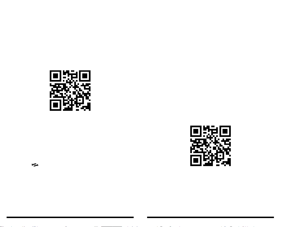
To download the scheduling app, scan the following QR codes as appropriate or
search the download shop for the Garnet Programmer application.
Once the application is downloaded to your mobile phone, it is imperative that
you activate the “Airplane” mode on your mobile phone, or switch o mobile data
transmission.
Download App
Click Here

12 13
Follow the steps below:
1) Press the button on the board that says “AP ENABLE” . This will cause the
communicator to generate a WiFi network for a period of 5 minutes.
2) Search your phone for available WiFi networks and connect to the WiFi network
named “4G-MAX-Gxxxxxx”.
3) Enter the default network password: admin1234 .
4) Once the communicator enters programming mode.
The LEDs will behave as follows
If this result is not achieved. Repeat the steps from the beginning. It is essential
that the mobile phone is in “Airplane” mode when connecting to the module’s WiFi
network.
5) Once ready, open the Garnet Programmer application and follow the instruc-
tions you wish to program.
Enabling Phones Panels DSC
From your phone shop download the “Garnet Control” User application.
Once you have downloaded the application you will need to register using your
personal details.
Then within the application press the “+” button to add a new system, you must
tick the option that you have a DSC alarm panel.
Antenna Wi Antenan Data Comunic Wi Comunic Data
Signal 1-5
No Signal
ACK
NAK
Download App
Click here
You must then initiate the connection to your phone from the communicator. You
will need to press the “AP ENABLED” button 3 times in a row, or if you have an LCD
keypad press [ ] + 8 + 7.
Conrmation of successful enablement will be by ashing the 4 upper antenna
and communications indication LEDs.
Then press the “Verify” button on your mobile phone. In seconds your application
will be ready for use.
Note: The Garnet Control application allows up to 20 total users to be associated.
Each user that registers in the app can have a dierent user code that must be
previously loaded in the alarm panel. If
each user is congured with a dierent code, this will be identied in the event
memory, and the user responsible for arming and/or disarming can be identied.
Videos from programming
Garnet Programmer
In the following QR Code you will nd all the necessary information for the
programming of the communicator and its respective alarm panel. If you are
unable to program the equipment, you will be able to see the following intuitive
information.
Reset the communicator conguration to the values of
factory
To reset the communicator to factory defaults, the “AP ENABLED” button must
be pressed for more than 6 seconds, until all antenna and communications LEDs
ash together.
Video Garnet Programmer
Click here
14 15
Remote Control with Communicators 4G-MAX-G/IP-500G
The above-mentioned models can be controlled by dierent means. In principle,
4G-MAX-G communicators allow communication via mobile data, WiFi networks
and text messages (SMS), while IP-500G communicators allow communication only
via WiFi networks.
This allows panels to be controlled via mobile applications and/or SMS (traditional
text messaging).
All modes are explained individually in the following sections.
Remote Control with 4G-MAX-G/IP-500G Communicators
via APP Garnet Control
The control of the panels will be carried out by any of the above mentioned com-
municators via the Garnet Control APP using the Internet.
This means that both the 4G-MAX-G/IP-500G communicators must have stable
connectivity to the Internet by any possible means of operation as well as your
mobile phone.
You should proceed to associate your mobile device with the App, if you are an
Administrator or Owner of the panel you should consult the “Enabling Phones”
section of the installer’s manual or contact your installer and/or monitoring
company. If you are an Administrator or Owner and wish to invite more users to
control your system, you must go to the Community tab within the application and
invite the remaining users.
Remote Control using Communicator
4G-MAX-G via SMS (Text Message)
Control of the panels with the 4G-MAX-G communicators can be done via mobile
data, but if the communicator does not have Internet because the chip does not
have mobile data, or your phone is in the same situation, the communicators
allow control via text messages (SMS).
For this it is important to take into account three parameters:
• Mobile number: We must know the telephone number of the caller in order to
be able to send messages.
• Partition key: This key must be recorded in the communicator conguration,
depending on which key we use we can manage the dierent partitions of the
system.
• Syntax of the message: We must respect the explicit syntax in the following
table in order to send text messages and for the panel to interpret them correctly.
Command format: [s][key][s][command][s][parameter].
Where:
• [s] is a space
• [key] is the partition key programmed in the communicator.
• [s] is a space
• [command] is the action we want to execute
• [s] is a space
• [parameter] is the complement of the action
Parameters
The possible parameters for the Inhibit and Uninhibit commands are as follows:
z01, z02, z03, z04, z05... z32
The possible parameters for the Enable and Disable commands are as follows:
siren, pgm1, pgm2, pgm3, pgm4, pgmw1, pgmw2, pgmw3, pgmw4, pgmw1,
pgmw2, pgmw3, pgmw4
Note: Zone parameters must contain two digits, if we want to bypass zone 5 we
must enter the command Inhibit z05, bearing in mind that the letter “z” must
always be in lower case.
Here are some examples of text messages.
Let’s remember the format of the commands:
[s][clave][s][comando][s][parámetro]
Examples:
• 1234 arming
• 1234 uninhibit z05
• 1234 activate siren
• 1234 activate pgmw2
• 1234 reset
Action
Setting up the system
Disarming the system
Bypass a zone
Desanitise an area
Activate a programmable output/Siren
Desactivate a programmable output
Check status
Communicator reset
Upgrade the communicator rmware
Command
Assemble
Disassemble
Inhibit
Uninhibit
Activate
Desactivate
State
Reset
Upgrade rmware
Parameter
See “parameters” section
See “parameters” section
See “parameters” section
See “parameters” section

16 17
NOTES
NATIONAL WARRANTY: Alonso Hnos. Sirenas S.A. (Garnet Technology) warrants to the original purchaser that, for a pe-
riod of 18 months from the date of purchase, the product is free from defects in materials and workmanship under normal
use. During the warranty period, Alonso Hnos Sirenas S.A., decides whether to repair or replace any defective product.
Any replacement or repaired part is warranted for the remainder of the original warranty or ninety (90) days, whichever
is longer. The original owner must promptly notify Alonso Sirens Bros.
S.A. in writing that there is a defect in material or workmanship, such written notice must be received in any event prior
to the expiration of the warranty period. There is absolutely no warranty of any kind on software. The purchaser assumes
all responsibility for the proper selection, installation, operation and maintenance of any product purchased from Alonso
Hnos. Sirenas S.A.
INTERNATIONAL GUARANTEE: The guarantee for international customers is the same as for any customer in Argentina,
with the exception that Alonso Hnos. Sirenas S.A. will not be responsible for any customs costs, transport and/or taxes
or duties that may be applied.
WARRANTY PROCEDURE: To obtain service under this warranty, please return the item(s) in question to the point of
purchase. All authorized dealers have a warranty program. Anyone returning items to Alonso Hnos Sirenas S.A. must rst
obtain an authorization number. Alonso Hnos. Sirenas
S.A. will not accept any return shipment without rst obtaining an authorisation number through the RMA process.
FACTORS THAT VOID THE WARRANTY: THIS WARRANTY APPLIES ONLY TO DEFECTS IN MATERIALS AND WORKMANSHIP
RELATING TO NORMAL USE. IT DOES NOT COVER:
• Damage incurred in the handling of shipment or transport.
• Damage caused by disasters such as re, ood, wind, earthquake or lightning, etc...
• Damage due to causes beyond the control of Alonso Hnos Sirenas S.A., such as excessive voltage, mechanical shock or
water damage.
• Damage caused by unauthorised attachments, alterations, modications or foreign objects.
• Damage caused by peripherals (unless the peripherals were supplied by Alonso Hnos. Sirenas S.A.).
• Defects caused by failure to provide a suitable environment for the installation of the products.
• Damage caused by the use of products for purposes other than those for which they were designed.
• Damage due to improper maintenance.
• Damage caused by other abuse, mishandling or improper application of the products.
ITEMS NOT COVERED BY THE WARRANTY
In addition to the items that cancel the Guarantee, the following items will not be covered by the Guarantee:
(I) Freight cost to the repair centre;
(II) Products that are not identied with the Alonso Hnos. Sirenas S.A. product label and its batch number or serial num-
ber;
(III) Products that have been disassembled or repaired in a manner that adversely aects performance or does not per-
mit adequate inspection or testing to verify any warranty claim;
(IV) Products not covered by this warranty, or otherwise out of warranty due to age, misuse or damage, will be evaluated
and an estimate for repair will be provided. No repair work will be performed until a valid purchase order submitted by
the Customer is received and a Return Merchandise Authorization (RMA) number is issued.
Sirenas S.A.’s liability for failure to repair the product under this warranty after a reasonable number of attempts shall be
limited to a replacement of the product. In no event shall Alonso Hnos. Sirenas S.A., be liable for any special, incidental
or consequential damages based on breach of warranty, breach of contract, negligence, strict liability or any other legal
theory. Such damages shall include, but not be limited to, loss of prots, loss of products or any associated equipment,
cost of capital, cost of substitutes or replacement equipment, facilities or services, downtime, buyer’s time, claims of third
parties, including customers, and property damage. The laws of some jurisdictions limit or do not allow the disclaimer of
consequential damages. If the laws of such jurisdiction are applicable to any claim by or against Alonso Hnos Sirenas S.A.,
the limitations and disclaimers contained herein shall be the broadest permitted by law. Some states do not allow the
exclusion or limitation of incidental or consequential damages, so the above may not apply to you.

18
DISCLAIMER OF WARRANTIES: This warranty contains the entire warranty and shall prevail over all other warranties
and all other warranties, whether expressed or implied (including all warranties implied on the goods or intended for a
particular purpose) and all other obligations or liabilities on the part of Alonso Hnos. Sirenas S.A., who neither assumes
nor authorizes any other person to act on its behalf, to modify or change this warranty, nor to assume any other warranty
or liability concerning this product. This limited warranty disclaimer is governed by the government and laws of the
province of Buenos Aires, Argentina.
WARNING: Alonso Hnos. Sirenas S.A. recommends that the entire system be fully tested for integrity on a regular basis.
However, despite frequent testing, and due to, but not limited to, criminal sabotage or electrical interruption, it is possible
that this product may fail to operate as expected. Out of Warranty Alonso Hnos Sirenas S.A. will elect to replace or repair
out of warranty products that are returned to its factory in accordance with the following conditions: Anyone returning
products to Alonso Hnos. Sirenas S.A. must rst obtain an authorization number. Alonso Hnos. Sirenas S.A. will not accept
any shipment without an authorization number rst. Products that Alonso Hnos. Sirenas S.A. determines to be repaira-
ble will be repaired and returned. A xed charge, which Alonso Hnos. Sirenas S.A. has predetermined and which will be
reviewed from time to time, is required for each unit repaired. Products that Alonso Hnos. Sirenas S.A. determines to be
unrepairable will be replaced with the most equivalent product available at that time. The current market price of the
replacement product will be charged for each unit replaced.
Rev. 09/05/2023
Table of contents
Other Garnet Cell Phone manuals


