Garnet SPILLSTOP ULTRA 815-U User manual

Page 1815U Manual
Printed in Canada
www.garnetinstruments.com
TM
SPILLSTOP ULTRA
Overll Prevention System
MODEL 815-U MANUAL

Page 2 815U Manual
Table of Contents
CHAPTER 1 - OVERVIEW ...................................................................... 3
CHAPTER 2 - FEATURES AND OPERATION......................................... 4
CHAPTER 3 - INSTALLATION GUIDE ................................................... 7
CHAPTER 4 - WIRING DIAGRAMS...................................................... 11
CHAPTER 5 - TROUBLESHOOTING GUIDE......................................... 12
CHAPTER 6 - SERVICE AND WARRANTY INFORMATION................ 13
MAIL IN WARRANTY .......................................................................... 15
GARNET
SPILLSTOP ULTRA
TM
Overll Prevention System
MODEL 815-U MANUAL
815-U Manual_v2.0 - 25-Jan-18

Page 3815U Manual
C
ongratulations on purchasing the Garnet Instruments Model
815 SPILLSTOP ULTRA
™
overll prevention system. The
SPILLSTOP
represents the state of the art in spill control for crude
oil and chemical hauling. The
SPILLSTOP™
is designed to work in
conjunction with a Garnet Model 810PS2 SEELEVEL PROSERIES
™
or a
Model 808P2 SEELEVEL SPECIAL
™
system to assist the truck operator
with truck tank overll protection in applications where the uid is
loaded with a PTO driven pump.
T
he 815U system is designed as an emergency backup system. The
operator should still be responsible for loading and unloading of
the tank, but in the event that the operator is unable to shut down
loading when the tank is full, the 815U system will prevent a spill.
The 815U is easy to install and operate, and is designed to
withstand the rigors of mobile applications. The Model 817 Truck
Gauge Programmer is used to set the alarm points in the 810PS2
SEELEVEL PROSERIES
™
or the 808P2 SEELEVEL SPECIAL
™
gauge, which
are programmed with the horn alarm and shutdown points. The
system can shut down either the truck engine or hydraulically
operated loading pumps. A horn alarm is provided to warn of an
impending shut down condition.
CHAPTER 1 - OVERVIEW
Page 4 815U Manual
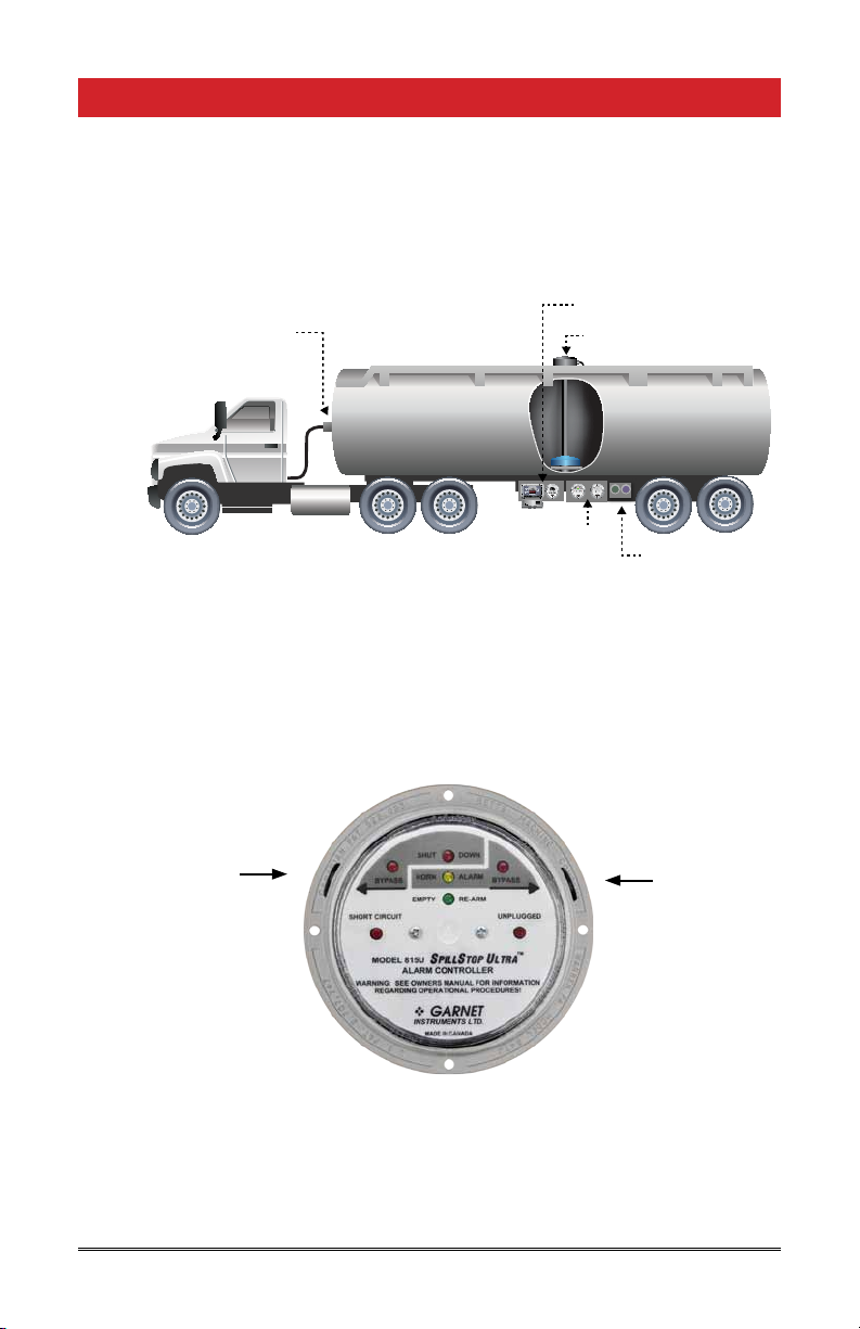
The following sketch shows the basic components and
connections of the SPILLSTOP for a tractor trailer application.
A body truck application would be similar except that the 7 pin
plug & socket would not be required since the tank is never
disconnected from the truck.
MODEL815UD
DUALALARMCONTROLLER
WARNING:SEEOWNERSMANUALFORINFORMATION
REGARDINGOPERATIONALPROCEDURES!
SPILLSTOPULTRA
TM
UNPLUGGED
SHUTDOWN
HORNALARM
TANKEMPTY
RE-ARM
SHORTCCT
PUMP ON
REARFRONT
PERMITTHERMB
OPTIC THERMA
MODEL688
OPTIC/THERMISTORLOADINGRACKCONTROLLER
MultiRackTM
SHUT DOWN
HORN ALARM
EMPTY RE-ARM
BYPASS BYPASS
SHORTCIRCUIT UNPLUGGED
MODEL815U
WARNING:SEEOWNERSMANUALFORINFORMATION
REGARDINGOPERATIONALPROCEDURES!
S
PILL
S
TOP
U
LTRA
TM
ALARMCONTROLLER
810-X Bar
815U SPILLSTOP
Controller and
688 MULTIRACK
7 Pin Plug
& Socket
Rack Plugs Wired
to MULTIRACK
808P2 SEELEVEL SPECIAL
or 810PS2 SEELEVELPROSERIES 2
The SPILLSTOP consists of three main components: the controller
on the truck, the optional plug module inside the 7 pin socket
housing on the trailer, and the gauge module inside the SeeLeveL
PROSERIES
truck gauge (the gauge module is built in to the SeeLeveL
Special display).
The 815U alarm controller monitors and displays the alarm status
of the gauge, and activates a horn if the uid level in the truck tank
is at the full point, and shuts off the pump or vehicle engine if a
spill is imminent. Each 815 Ultra controller accommodates one
compartment.
Horn Alarm Bypass Button
Shut Down Bypass Button
CHAPTER 2 - FEATURES AND OPERATION

Page 5815U Manual
WARNING: The SPILLSTOP ULTRA is intended as an emergency
backup system only, and is not intended as a substitute for
operator diligence during the loading process.
The operation of the SPILLSTOP Ultra during the loading operation
is as follows: When the tank is empty, the green EMPTY/RE-
ARM indicator is on, the horn is off, and the engine or pump is
allowed to run. As the uid level starts to rise, the EMPTY/RE-
ARM indicator goes out. When the horn alarm point is reached,
the yellow HORN ALARM indicator comes on and the horn is
activated with a 1 second on, 1 second off cycle. Depressing the
horn alarm BYPASS at this point lights the red horn alarm bypass
indicator and silences the horn. If the uid level continues to rise
and reaches the engine shutdown point, the red SHUT DOWN
indicator will come on and the pump or truck engine will be shut
off. Depressing the shutdown BYPASS at this point lights the red
shutdown bypass indicator and allows the pump or engine to be
restarted. When either one of the BYPASS switches are depressed,
the associated alarm indicator remains on even though the alarm
function has been suppressed; this reminds the operator that
the uid level situation which triggered the alarm still exists. As
the tank is unloaded the alarm indicators will go out when the
uid level drops below the alarm points, and the bypasses will
be cleared (the system is re-armed) when the EMPTY/RE-ARM
indicator comes back on. This automatic feature means that
there is no need for the operator to re-arm the system, removing
the possible operator error of forgetting to re-arm. If the tank is
not lled to the alarm point, the system can still be bypassed to
prevent sloshing from sounding the horn or shutting down the
engine during driving. If the tank is to be lled from more than
one location, the alarms can be bypassed during driving between
loading sites, and the system manually re-armed to re-establish
spill protection for the second load. Re-arming is done by pressing
both of the BYPASS buttons at the same time for two seconds.
The SPILLSTOP Ultra has a number of convenience and safety
features built into it. When the tank is empty, the bypasses will
not work, preventing accidental bypassing before loading. Delays
are incorporated into the system to prevent electrical noise or
momentary bad connections from disrupting operation. A short
circuit in the wiring to the gauge, or plugging the SPILLSTOP plug
into the trailer lighting socket, lights the red SHORT CIRCUIT
indicator and shuts down the pump or engine. An open circuit
in the wiring to the gauge, or a disconnection of the plug to the
trailer, lights the red UNPLUGGED indicator, sounds the horn, and
shuts down the pump or engine. The alarms from an unplugged
situation can be bypassed to allow operating the tractor without
the trailer connected. The pulse signal between the gauge and the

Page 6 815U Manual
controller cannot be corrupted by poor connections or moisture
in the wiring; if the signal is too badly degraded it defaults directly
to an open or short circuit condition. A failure of the
SEELEVEL
or
SEELEVEL
Special gauge causes the controller to default to the horn
alarm and shut down condition. The controller will operate at
truck voltages from 8 to 16 volts, and draws less than 1/8 amp so
it can operate from any convenient 12 volt circuit. The controller
is also fully weatherproof, so it can be mounted outside of the cab
of the truck.

Page 7815U Manual
Refer to the appropriate wiring diagram during installation of
the SPILLSTOP system. The wiring diagrams are in chapter 4.
Follow these instructions for a tractor trailer installation:
1. Pick a spot for the SPILLSTOP Ultra controller to be mounted. It
can be inside or outside of the cab, but it should be mounted
on the truck, rather than the trailer. The only situation
where the controller can be mounted on a trailer is where
the loading pump is also located on the trailer so that the
shutdown wiring does not need to go through a plug. In this
case the 12 volt power should be generated at the trailer, or
a loss of power to the trailer should result in the shutdown of
the loading pump. Do not mount the controller where it can
be kicked and it should be easy to see and out of direct road
spray. It is recommended that the controller be mounted
close to the PTO control.
2. Mount the display enclosure using the mounting ange holes,
being certain to shim the enclosure away from the mounting
surface with the spacers provided to allow water drainage.
Broken display enclosures caused by water freezing
behind the enclosure are NOT covered by warranty.
IMPORTANT: When connecting wiring, all connections should
be soldered.
3. Mount a standard 7 pin socket to the front of the trailer and a
7 pin plug and cable from the tractor.
4. A single wire needs to be connected between the green wire
of the 808P2, the grey wire of the 810PS2 and the yellow wire
of the 815U SPILLSTOP Ultra controller through the 7 pin socket.
From inside the displays, seal the wire entry into the
SEELEVEL
enclosure with RTV silicon rubber. Make sure that the RTV
fully surrounds the wire where it goes though the tting.
5. Connect the 808P2 or 810PS2 and the 815U SPILLSTOP Ultra
controller to the same chassis ground using each displays
ground wires. Verify the truck and trailer are grounded
together through the 7 pin plug.
6. Connect the 815U controller red wire to a 12 volt source.
This 12 volt source should be an ignition source so the truck
battery is not drained when the truck is off.
7. Locate an electrical shutoff switch (such as the key switch) in
the truck. Break the connection to the switch and connect
the two wire ends to the contact terminals (#30 & #87) of the
CHAPTER 3 - INSTALLATION GUIDE

Page 8 815U Manual
auxiliary ESD relay (supplied). Connect one of the auxiliary
ESD relay coil terminals (#86) to the 12 volt source and the
other coil terminal (#85) to the green wire in the controller. It
is a good idea to mount the auxiliary ESD relay close to the
existing shutoff wiring to minimize any extra wire length in the
truck shutoff circuit.
8. Connect the PTO sense relay (supplied) as shown in the wiring
diagram. Use a standard clearance lamp (not supplied) as the
PTO indicator light. The PTO sense relay functions so that the
ESD (Engine Shutdown) relay cannot operate unless the PTO
is engaged. This prevents the engine from being accidentally
shutdown if uid sloshing occurs and raises the oat above
the engine shutdown point.
9. Connect the orange controller wire to the truck’s electrical
horn switch (or button). Make sure that grounding this
connection will cause the horn to sound. This connection is
normally to the horn relay coil, not to the horn itself.
10. Program the alarm points in the gauges. Program alarm #1 as
SHUT DOWN at the point where the engine or pump should
be shut down. Program alarm #2 as SHUT DOWN at the point
where the horn alarm should come on. Program alarm #3 as
SHUT DOWN at the point where the tank is considered empty,
normally a few inches off the bottom. Do not program the
empty point right at the bottom, since any buildup of debris
on the anchor will prevent the system from clearing the
bypasses. See the 808P2 or 810PS2 manual for programming
details.
Example: The tank is 58 inches high, with a bottom reading of 4.6
inches. Suggested points would be alarm #1 at 55 inches, alarm
#2 at 53 inches, and alarm #3 at 6 inches.
WARNING: To properly determine the shutdown point, raise the
SEELEVEL
oat to the top of the tank, and then lower the oat by at
least one inch. Record this point as the shutdown value. Ensure
that the truck operator is aware of this value. Ensure that
this value and the empty reading are recorded in the provided
area in the operator’s manual. The truck operator must be
given the owners manual upon delivery with all front page
data lled in.
11. Put the cover back on the
SEELEVEL
gauge, and test the system
for proper operation by lifting the oat. As the oat is raised,
the horn should turn on rst, and then the engine or pump
should shut off with the oat at least one inch below the top
of the tank. Bypass the horn and shutdown and ensure that
the bypasses are removed with the oat at least one inch
above the bottom of the tank.

Page 9815U Manual
Follow these instructions for a body truck installation:
1. Pick a spot for the SPILLSTOP Ultra controller to be mounted.
It can be inside or outside of the cab. Do not mount the
controller where it can be kicked and it should be easy to
see and out of direct road spray. It is recommended that the
controller be mounted close to the PTO control.
2. Mount the display enclosure using the mounting ange holes,
being certain to shim the enclosure away from the mounting
surface with the spacers provided to allow water drainage.
Broken display enclosures caused by water freezing
behind the enclosure are NOT covered by warranty.
IMPORTANT: When connecting wiring, all connections should
be soldered.
3. A single wire needs to be connected between the green wire
of the 808P2, the grey wire of the 810PS2 and the yellow
wire of the 815U SPILLSTOP Ultra controller. From inside the
displays, seal the wire entry into the
SEELEVEL
enclosure with
RTV silicon rubber. Make sure that the RTV fully surrounds the
wire where it goes though the tting.
4. Connect the 808P2 or 810PS2 and the 815U SPILLSTOP Ultra
controller to the same chassis ground using each displays
ground wires.
5. Connect the 815U controller’s red wire to a +12 volt source.
This +12 volt source should be an ignition source so the truck
battery is not drained when the truck is off.
6. Locate an electrical shutoff switch (such as the key switch) in
the truck. Break the connection to the switch and connect
the two wire ends to the contact terminals (#30 & #87) of the
auxiliary ESD relay (supplied). Connect one of the auxiliary
ESD relay coil terminals (#86) to the 12 volt source and the
other coil terminal (#85) to the green wire in the controller. It
is a good idea to mount the auxiliary ESD relay close to the
existing shutoff wiring to minimize any extra wire length in the
truck shutoff circuit.
7. Connect the PTO sense relay (supplied) as shown in the wiring
diagram. Use a standard clearance lamp (not supplied) as the
PTO indicator light. The PTO sense relay functions so that the
ESD (Engine Shutdown) relay cannot operate unless the PTO
is engaged. This prevents the engine from being accidentally
shutdown if uid sloshing occurs and raises the oat above
the engine shutdown point.

Page 10 815U Manual
8. Connect the 815U controller’s orange wire to the truck’s
electrical horn switch (or button). Make sure that grounding
this connection will cause the horn to sound. This connection
is normally to the horn relay coil, not to the horn itself.
9. Program the alarm points in the gauges. Program alarm #1 as
SHUT DOWN at the point where the engine or pump should
be shut down. Program alarm #2 as SHUT DOWN at the point
where the horn alarm should come on. Program alarm #3 as
SHUT DOWN at the point where the tank is considered empty,
normally a few inches off the bottom. Do not program the
empty point right at the bottom, since any buildup of debris on
the anchor will prevent the system from clearing the bypasses.
See the 808P2 or 810PS2 manuals for programming details.
Example: The tank is 58 inches high, with a bottom reading of
4.6 inches. Suggested points would be alarm #1 (shutdown) at
55 inches, alarm #2 (horn) at 53 inches, and alarm #3 (reset) at 6
inches.
WARNING: To properly determine the shutdown point, raise the
SEELEVEL
oat to the top of the tank, and then lower the oat by at
least one inch. Record this point as the shutdown value. Ensure
that the truck operator is aware of this value. Ensure that
this value and the empty reading are recorded in the provided
area in the operator’s manual. The truck operator must be
given the owners manual upon delivery with all front page
data lled in.
10. Put the cover back on the
SEELEVEL
gauge, and test the system
for proper operation by lifting the oat. As the oat is raised,
the horn should turn on rst, and then the engine or pump
should shut off with the oat at least one inch below the top
of the tank. Bypass the horn and shutdown and ensure that
the bypasses are removed with the oat at least one inch
above the bottom of the tank.

Page 11815U Manual
EXISTING
KEY
SWITCH
FROM UNSWITCHED
+12 VOLT
BREAK
SINGLE COMPARTMENT WIRING DIAGRAM
#85#86
#30#87
AUX
ESD
RELAY
- COIL -
- CONTACTS -
EXISTING
HORN
SWITCH
BLACK GREEN
SeeLeveL
Special
GAUGE
LIGHT
INDICATOR
PTO
PTO PRESSURE SWITCH
(CLOSED WHEN PTO ENGAGED)
#85#86
#30
#87
PTO
SENSE
RELAY
COIL
CONTACTS
#87A
NOTE: Relay contacts 30 and 87A are the
normally closed (NC) contacts.
Relay contacts 30 and 87 are the
normally open (NO) contacts.
TO FUEL SHUTOFF
FROM HORN
RED (12V INPUT)
YELLOW (GAUGE)
GREEN (SHUTDOWN)
SPILL STOP
ULTRA
CONTROLLER
ORANGE (HORN)
BLACK (GROUND)
WITH PTO PRESSURE SWITCH APPLICATION
CHAPTER 4 - WIRING DIAGRAMS
Wiring Guide
Wire Color Operation
Yellow Signal Line
Green Shutdown output
Orange Horn alarm output
Black Ground
Red +12VDC
Purple Horn alarm bypass wire
White Shutdown bypass wire

Page 12 815U Manual
IF problems are encountered, check the following:
1. Is the controller getting at least 8 volts?
2. Are all the wires properly connected, with no short circuits?
3. Are the 808P2 or 810PS2
SEELEVEL
gauges working properly?
4. Are the 808P2 or 810PS2
SEELEVEL
gauges programmed
properly?
5. If the horn is not sounding, does the horn itself work?
To test the various components, substitute a known good
component to see if the rest of the system is working. If the
engine will not start, ground the green wire from the controller.
If the engine still does not start, the problem is in the relay or
associated wiring. If the engine now starts, and the controller
indicates no shutdown alarm (or is bypassed), then the controller
is bad. If the horn will not sound, ground the orange wire from
the controller. If the horn still does not sound, the problem is in
the horn or associated wiring. If the horn now sounds, and the
controller indicates a horn alarm that is not bypassed, then the
controller is bad.
CHAPTER 5 - TROUBLESHOOTING GUIDE

Page 13815U Manual
CHAPTER 6 - SERVICE AND WARRANTY INFORMATION
T
he warranty will only apply only if the warranty card that is shipped with the equipment
has been returned to Garnet Instruments Ltd.
DISCLAIMER OF WARRANTY ON HARDWARE
Garnet Instruments Ltd. warrants equipment manufactured by Garnet to be free from defects
in material and workmanship under normal use and service for a period of one year from the
date of sale from Garnet or an Authorized Dealer. The warranty period will start from the date
of purchase or installation as indicated on the warranty card. Under these warranties, Garnet
shall be responsible only for actual loss or damage suffered and then only to the extent of
Garnet’s invoiced price of the product. Garnet shall not be liable in any case for labor charges
for indirect, special, or consequential damages. Garnet shall not be liable in any case for
the removal and/or reinstallation of defective Garnet equipment. These warranties shall not
apply to any defects or other damages to any Garnet equipment that has been altered or
tampered with by anyone other than Garnet factory representatives. In all cases, Garnet will
warrant only Garnet products which are being used for applications acceptable to Garnet and
within the technical speci cations of the particular product. In addition, Garnet will warrant
only those products which have been installed and maintained according to Garnet factory
speci cations.
LIMITATION ON WARRANTIES
These warranties are the only warranties, expressed or implied, upon which products are
sold by Garnet and Garnet makes no warranty of merchantability or tness for any particular
purpose in respect to the products sold. Garnet products or parts thereof assumed to be
defective by the purchaser within the stipulated warranty period should be returned to the
seller, local distributor, or directly to Garnet for evaluation and service. Whenever direct
factory evaluation, service or replacement is necessary, the customer must rst, by either
letter or phone, obtain a Returned Material Authorization (RMA) from Garnet Instruments
directly. No material may be returned to Garnet without an RMA number assigned to it or
without proper factory authorization. Any returns must be returned freight prepaid to: Garnet
Instruments Ltd, 286 Kaska Road, Sherwood Park, Alberta, T8A 4G7. Returned warranted
items will be repaired or replaced at the discretion of Garnet Instruments. Any Garnet items
under the Garnet Warranty Policy that are deemed irreparable by Garnet Instruments will be
replaced at no charge or a credit will be issued for that item subject to the customer’s request.
If you do have a warranty claim or if the equipment needs to be serviced, contact the
installation dealer. If you do need to contact Garnet, we can be reached as follows:
CANADA UNITED STATES
Garnet Instruments Ltd. Garnet Technologies Inc.
286 Kaska Road 201 M&M Ranch Road
Sherwood Park, AB T8A 4G7 Granbury, TX 76049
CANADA USA


MODEL NO. SERIAL NO.
DATE PURCHASED DATE INSTALLED
YR/MO/DAY YR/MO/DAY
COMPANY NAME
PRINCIPAL CONTACT
ADDRESS
TELEPHONE FAX
IN CANADA RETURN TO:
Garnet Instruments Ltd.
286 Kaska Road
Sherwood Park, AB T8A 4G7
CANADA
SENDER BAR SERIAL NO. (if applicable)
IMPORTANT: WITHOUT THE SERIAL NUMBER OF EACH UNIT IT IS
DIFFICULT TO DETERMINE WARRANTY VALIDITY
DEALERS NAME
WARRANTY CONTACT
ADDRESS
TELEPHONE FAX
IN UNITED STATES RETURN TO:
Garnet Technologies Inc.
201 M&M Ranch Road
Granbury, TX 76049
USA
IMPORTANT: RETURNING THIS CARD WILL ENABLE US TO NOTIFY YOU IN THE EVENT OF A PRODUCT RECALL OR TO SUPPLY YOU WITH REQUIRED PRODUCT SAFETY INFORMATION.
TO MAXIMIZE YOUR WARRANTY PLEASE REGISTER ONLINE AT www.garnenstruments.com OR MAIL THIS FORM IN TO GARNET.
LIMITED WARRANTY REGISTRATION
MAIL IN WARRANTY


Printed in Canada
www.garnetinstruments.com
CANADA
Garnet Instruments Ltd.
286 Kaska Road
Sherwood Park, AB T8A 4G7
USA
Garnet Technologies Inc.
201 M&M Ranch Road
Granbury, TX 76049
P: 780-467-1010
F: 780-467-1567
TF: 1-800-617-7384
P: 817-578-8601
F: 817-573-0005
TF: 1-877-668-7813
Table of contents
Other Garnet Controllers manuals


