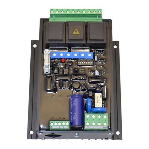
EMRI LX449 User manual

Voltage regulator for generators
April 2012 Instruction Manual
LX449
CAN addendum

Generator rewinding & repair. Voltage regulator products CAN Addendum LX449
Version : 19-12-2011 15:05:00 Page 2 of 8
Electronics
WARNINGS
The manual does not cover all technical details of the product. Specifications may be modified
by the manufacturer without notice. For further information, the manufacturer should be
contacted.
WARNING
The system should not be installed, operated, serviced or
modified
except by qualified personnel who understand
the danger of electric shock hazards and have read and
understood the user instructions
ELECTRICAL HAZARDOUS VOLTAGES
DANGEROUS DO NOT OPERATE WHEN
NOT FAMILIAR WITH GENERATORS
WARNING
Dangerous voltages are present at the voltage regulator
board. Accidental contact with live conductors could result
in serious electrical shock or electrocution.
Disconnect the power source before making repairs,
connecting test instruments, or
removing or making
connections to the voltage regulator or generator.
WARNING
Never work on a LIVE generator. Unless there is another
person present who can switch off the power supply or
stop the engine

Generator rewinding & repair. Voltage regulator products CAN Addendum LX449
Version : 19-12-2011 15:05:00 Page 3 of 8
Electronics
Table of contents
1. CAN-bus addendum LX449
1.1 CAN-bus 4
1.1.1 Introduction 4
1.1.2 Can connector layout 4
1.1.3 CAN heartbeat 5
1.1.4 CAN AVR measurements & status 5
1.1.5 CAN control 7
Appendix
A.1 Contact 8

Generator rewinding & repair. Voltage regulator products CAN Addendum LX449
Version : 19-12-2011 15:05:00 Page 4 of 8
Electronics
1. CAN-bus addendum LX449
1.1 CAN-bus
1.1.1 Introduction
The LX449 AVR is equipped with a CAN bus interface. The CAN interface enables the user
to obtain detailed information about the AVR status, measured quantities and to adjust AVR
control setpoints.
The interface complies with CAN specification 2.0B. The AVR communication operates at a
transfer rate of 250kBit/s and uses standard frame (11-bit) message identifiers.
1.1.2 CAN connector layout
Terminate header next to the CAN connector. Shorting this header enables an 120W
termination resistor.
Diagram 1. CAN Connector

Generator rewinding & repair. Voltage regulator products CAN Addendum LX449
Version : 19-12-2011 15:05:00 Page 5 of 8
Electronics
1.1.3 CAN heartbeat
The AVR sends a heartbeat signal when the CAN bus interface is enabled and the AVR is
powered. This signal may be used to assess the proper functioning of the CAN bus
communication.
The heartbeat consists of a message with ID 0x70A and is sent every 250ms. The message
content is 1 byte long and alternating 0x05 or 0x85 .
Heartbeat
ID:0x70A
Byte
Description
Value
Remarks
0Alternating heartbeat 0x05 ~ 0x85
Table 1. CAN heartbeat
1.1.4 CAN AVR measurements & status
When the CAN bus is enabled and the AVR is powered a message containing AVR
measurements and the present AVR status is sent. The message with ID 0x18A is sent every
500ms. The definition of the 8 byte content is described in table 2 onwards.
AVR measurements & status
ID:0x18A
Byte
Description
Value
Unit
Remarks
0
Data Page
1-2
Indicates Data Page
1 - 7
Dependant on page number (see tables below)
Table 2. CAN measurements & status
AVR measurements & status – Page 1
ID:0x18A
Byte
Description
Value
Unit
Remarks
0
Data Page
1
Indicates Data Page
1
Generator Voltage MSB
0 -
65535
0.0 V
2
Generator Voltage LSB
3
Generator Current Phase U MSB
0 -
65535
0 A
Valid for 1000A:1A CT.
4
Generator Current Phase U LSB
5
Generator Current Phase W MSB
0 -
65535
0 A
Valid for 1000A:1A CT.
6
Generator Current Phase W LSB
7
Generator Temperature
0-255
0 ºC
KTY 84-130 on terminals TH-TH
Table 3. CAN measurements & status – Page 1

Generator rewinding & repair. Voltage regulator products CAN Addendum LX449
Version : 19-12-2011 15:05:00 Page 6 of 8
Electronics
AVR measurements & status – Page 2
ID:0x18A
Byte
Description
Value
Unit
Remarks
0 Data Page 2 Indicates Data Page
1 Excitation Current MSB 0 -
65535 0 mA Excitation current
2 Excitation Current LSB
3 Generator Frequency 0-255 0 Hz
4 Generator Power Factor 0-255 - 0-127 = 0 – 1 capacitive
127-255 = 1 – 0 inductive
5
Protections
Bitwise register
bit 0 Overvoltage 0-1 bit 1 = protection triggered
bit 1 Overcurrent 0-1 bit 1 = protection triggered
bit 2
Overexcitation
0-1
bit
1 = protection triggered
bit 3 Loss of Voltage Sensing 0-1 bit 1 = protection triggered
bit 4 Overtemperature AVR 0-1 bit 1 = protection triggered
bit 5 Overtemperature Generator 0-1 bit 1 = protection triggered
bit 6 Loss of Excitation 0-1 bit 1 = protection triggered
bit 7 Loss of Current Sensing 0-1 bit 1 = protection triggered
6
AVR status
Bitwise register
bit 0
Status LED
0-7
0 = off
1 = green
2 = green blink
3 = orange
4= orange blink
5 = red
5 = red blink
bit 1
bit 2
bit 3
Controlled Quantity
0-7
0 = idle
1 = voltage control
2 = current control
3 = transition U-I
4 = power factor control
bit 4
bit 5
bit 6
Mode of Control
0-3 0 = idle
1 = build-up
2 = normal control
bit 7
7
AVR temperature
0-255
0 ºC
Table 4. CAN measurements & status – Page 2

Generator rewinding & repair. Voltage regulator products CAN Addendum LX449
Version : 19-12-2011 15:05:00 Page 7 of 8
Electronics
1.1.5 CAN control
For special applications it is possible remote control the AVR setpoints and limits over the
CAN bus referred to as CAN control. This option is not enabled by default and must be factory
configured.
To realize CAN control a message with ID 0x40A must be sent at least every 1 seconds
complying with the content definition described in table 5.
When CAN control is activated, but the AVR has not received a valid control message for the
last 1 seconds, CAN control is automatically disabled and normal AVR control is resumed.
Active CAN control is visualized by the CAN status LED signaling continuous orange.
Be aware that when the user enables CAN control over the voltage and/or excitation setpoints,
adjustments to the respective potentiometers on the AVR will have no immediate effect. The
adjustments will only then be effective when CAN control is disabled and AVR control is
resumed again.
CAN control
ID:0x20A
Byte
Description
Value
Unit
Remarks
0 Generator voltage setpoint 0-255 V Phase - Neutral
1 Excitation current ratio setpoint 0-100 % Overexcitation limit
2 - - - not used
3 - - - not used
4 CAN control Bitwise CAN commandregister
bit 0 Activate CAN voltage setpoint 1 - 0 bit 1 = active
bit 1 - 0 bit not used
bit 2 - 0 bit not used
bit 3 - 0 bit not used
bit 4 Activate CAN excitation ratio setpoint 1 – 0 bit 1 = active
bit 5 - 0 bit not used
bit 6 - 0 bit not used
bit 7 - 0 bit not used
5 - - - not used
6 - - - not used
7 - - not used
Table 5. CAN control

Generator rewinding & repair. Voltage regulator products CAN Addendum LX449
Version : 19-12-2011 15:05:00 Page 8 of 8
Electronics
A.1 Contact
See our website www.emri.nl for local suppliers
Rafeining ehf
Hafnarfjordur - Iceland
Tel: +354 565 3049
Fax: +354 565 3048
E-mail: rafeining@rafeining.is
Internet: www.rafeining.is
Frydenbø Electric A/S
Bergen - Norway
Tel: + 47 55 34 91 00
Fax: + 47 55 34 91 10
E-mail: firma.f[email protected]
Internet: www.frydenbo.no
Myren & Co. AB
Askim - Sweden
Tel: +46 317481860
Fax: +46 317481870
E-mail: myren@myren.com
Internet: www.myren.com
Yneldo Electronics
Roodepoort - South Africa
Tel: +27(0)117637053
Fax: +27(0)117634212
E-mail: yneldo@yneldo.com
Internet: www.yneldo.com
KDU Technical Services
Sharjah - United Arab Emirates
Tel: +971-6-5575480
Fax: +971-6-5575490
E-mail: kdutech@kdutech.ae
Internet: www.kdutech.ae
Cyclect Electrical Engineering
Singapore
Tel: +65 6868 6013
Fax: +65 6863 6260
E-mail: heng.p@cyclect.com.sg
Internet: www.cyclect.com.sg
Marel Serwis
Szczezin-Mierzyn - Poland
Tel: +48 91 48 58 388
Fax: +48 91 48 79 948
E-mail: handel@marel.szczecin.pl
Internet: www.marel.szczecin.pl
An-Elec Sp. z o.o.
Gdynia - Poland
Tel: +48 58 668 44 00
Fax: +48 58 668 44 66
E-mail: info@an-elec.pl
Internet: http://an-elec.pl
MJR Controls
Stockton on Tees - United Kingdom
Tel: +44 1642 762 151
Fax: +44 1642 762 502
Email: chris.milner@mjrcontrols.com
Internet: www.mjrcontrols.com
Stavros Kassidiaris S.A.
Piraeus - Greece
Tel: +30 210 4636000
Fax: +30 210 4624471
E-mail: info@kassidiaris.gr
Internet: www.kassidiaris.gr
Manufacturer:
EMRI Electronics B.V.
Morsestraat 10
6716 AH, Ede, Netherlands
Tel: (+31) 0318 620427
Fax: (+31) 0318 634615
Website: www.emri.nl
E-mail: info@emri.nl
Table of contents
Other EMRI Controllers manuals
Popular Controllers manuals by other brands
Rosslare
Rosslare AYC-Q54B Installation and programming manual
Generac Power Systems
Generac Power Systems PWRmanager owner's manual

Rockwell Automation
Rockwell Automation Allen-Bradley Logix5000 Programming manual
O. Thompson
O. Thompson Microflite Ultra 2000 Installation & Adjustment Manual
Sminn
Sminn BOX S 220 instruction manual

Denison Hydraulics
Denison Hydraulics Jupiter 900 manual

