Garrecht Avionik TRX-2000 User manual

Garrecht Avionik GmbH TRX-2000 ADS-B Traffic Monitor User Manual
Revision: 1.0b 1 19 DEC 2011
TRX-2000
ADS-B Trafficmonitor
User Manual
Installation Manual
© 2011 - Garrecht Avionik GmbH, 55411 Bingen/Germany

Garrecht Avionik GmbH TRX-2000 ADS-B Traffic Monitor User Manual
Revision: 1.0b 2 19 DEC 2011
Record of Revisions
Always keep this page in front of this document.
Date Revision
Pages
Description of Change Inserted
by
30 MAR 2011 1.0 All released JG
19 DEC 2011 1.0b All English Translation revised (courtesy to Steve
Hunt)
Added: several information about updates
procedures, Audio interface, configuration, max.
Receiving range
JG

Garrecht Avionik GmbH TRX-2000 ADS-B Traffic Monitor User Manual
Revision: 1.0b 3 19 DEC 2011
Table of contents
Record of Revisions................................................................................................................................................... 2
Table of contents....................................................................................................................................................... 3
Preface ...................................................................................................................................................................... 4
Unpacking the unit..................................................................................................................................................... 5
Important Information about integral FLARM® module.............................................................................................. 6
1. Principles............................................................................................................................................................... 7
1.1. General.......................................................................................................................................................... 7
1.2. Output of position data and warnings............................................................................................................. 9
1.2.1. Position data:.......................................................................................................................................... 9
1.2.2. Warnings:............................................................................................................................................. 10
1.3. Transponder signals, FLARM® signals and system behaviour.................................................................... 11
1.3.1. Mode-S Extended Squitter with ADS-B out.......................................................................................... 11
1.3.2. Mode-S Squitter ................................................................................................................................... 11
1.3.3. Mode-S Replies.................................................................................................................................... 11
1.3.4. FLARM® .............................................................................................................................................. 11
1.4. Limits of the Systems................................................................................................................................... 12
1.4.1. General................................................................................................................................................. 12
1.4.2. The TRX-2000 system provides........................................................................................................... 12
1.4.3. The TRX-2000 system does NOT provide............................................................................................ 12
2. Aircraft installation................................................................................................................................................ 13
2.1. General........................................................................................................................................................ 13
2.2. Panel installation.......................................................................................................................................... 13
2.3. Antenna installation...................................................................................................................................... 14
2.3.1. General................................................................................................................................................. 14
2.3.2. Antenne cable and connectors............................................................................................................. 14
2.3.3. ADS-B Antenna.................................................................................................................................... 14
2.3.4. FLARM TX/RX Antenna (devices with integral FLARM® module only)............................................... 15
2.3.5. GPS Antenna (devices with integral FLARM® module only)............................................................... 15
2.4. Wiring (power supply and data).................................................................................................................... 16
2.4.1. USB interface....................................................................................................................................... 16
2.4.2. Data interfaces (Port-1 to Port-4)......................................................................................................... 17
2.4.3. Audio interface ..................................................................................................................................... 20
3. Operation............................................................................................................................................................. 21
3.1. Human machine interface............................................................................................................................ 21
3.1.1. microSD Card Slot................................................................................................................................ 21
3.1.2. Double shaft rotary encoder................................................................................................................. 23
3.2. Switching on and off..................................................................................................................................... 24
3.3. System configuration.................................................................................................................................... 25
4. Traffic indication................................................................................................................................................... 26
4.1. Radar view................................................................................................................................................... 27
4.2. List view....................................................................................................................................................... 28
4.3. FlarmNET view............................................................................................................................................. 28
4.4. Traffic warning.............................................................................................................................................. 29
4.4.1. FLARM®- and ADS-B out targets......................................................................................................... 29
4.4.2. Mode-S targets without ADS-B out....................................................................................................... 29
4.5. Obstacle warnings........................................................................................................................................ 30
5. Firmware updates (FLARM + TRX-2000) via mircoSD-Card............................................................................... 31
5.1. Step by step instruction................................................................................................................................ 32
5.1.1. General information about required files .............................................................................................. 32
5.1.2. Prepare your microSD memory card (SDSC, no SDHC type) for the update process ......................... 32
5.1.3. Performe the update process............................................................................................................... 32
6. PC Software TRX-TOOL...................................................................................................................................... 33
6.1. Step by Step instruction for successfull installation process........................................................................ 33
6.2. Software and firmware release..................................................................................................................... 34
6.3. Program and firmware update via internet................................................................................................... 34
6.4. Device configuration..................................................................................................................................... 35
7. Check list installation and konfiguration............................................................................................................... 40
8. Specifications TRX-2000 ..................................................................................................................................... 41
9. Installation schematic diagram............................................................................................................................. 42
10. Dimensions........................................................................................................................................................ 43

Garrecht Avionik GmbH TRX-2000 ADS-B Traffic Monitor User Manual
Revision: 1.0b 4 19 DEC 2011
Preface
Many thanks for purchasing the TRX-2000 traffic monitor.
The TRX-2000 is a panel mounted system combining a high performance ADS-B receiver and a color
LCD for displaying the traffic situation. It has been designed either to be connected to an external
FLARM(R) or comes with an integral FLARM(R) module. The system provides interfaces for connecting
two external Displays (CDTI) and a GPS interface to be connected to a Mode-S transponder (i.e.
Garrecht Avionik VT-01, VT-02, VT-2000) with ADS-B out capability.
To avoid malfunction, reading and understanding of all chapters of this manual is required.
Limitations of the system are described in the chapter „System Limitations”
A detailed data port specification is described in the “TRX Data Port Specifications” manual, which is
available on request from the manufacturer.
New releases of manuals or firmware udpates are published on the manufacturers website
www.garrecht.com
Your feedback or suggestions for improving the system are welcome. Please contact us via email:
info@garrecht.com
This manual provides all information, that is required for proper installation and safe operation.
For more information and addtional support, please contact your TRX-2000 dealer. ´
To avoid damage, please do not open the system housing.
The following symbols and terms are used in this manual:
Warning
Warning statements identify conditions or practices that could result in
injury or loss of life
Caution
Caution statements identify conditions or practices that could result in
damage of this product or other property.
Important note:
Indicates important or usefull information. It is strongly recommended to
read, understand and follow the statement.

Garrecht Avionik GmbH TRX-2000 ADS-B Traffic Monitor User Manual
Revision: 1.0b 5 19 DEC 2011
Unpacking the unit
The TRX-2000 system is supplied with the following:
•System unir TRX-2000
•1:1 Patch cable (shielded) with RJ-45 connectors, lenght: 0,5m for connecting an external
FLARM(R)
•open end patch cable for supplying power (EIA/TIA 568B)
•USB interface cable
•1090 MHz antenna + antenna cable
•FLARM®- antenna + antenna cable (units with integral FLARM® module only)
•Antenna ground plane
•GPS antenna (units with integral FLARM® module only)
•This manual
If one or more parts are missing, please contact your supplier of the TRX-2000.
Required parts for proper operation
•Units without integral FLARM®: Original FLARM® or 3rd party licenced FLARM®
Options (not delivered with the TRX-2000)
•Antenna line extension
•Interconnection cable to GARMIN GPS series 39x/49x or 69x
•External display devices (CDTI), i.e. Butterfly, FlymapL, Garmin GPS 39x/49x/69x, PDA with
appropriate software (WinPilot, PocketStrePla, SeeYou mobile)
These options will be supplied by your TRX-2000 supplier.

Garrecht Avionik GmbH TRX-2000 ADS-B Traffic Monitor User Manual
Revision: 1.0b 6 19 DEC 2011
Important Information about integral FLARM® module
The TRX-2000 can be equipped with a FLARM® module optionally. FLARM is a very popular collision
avoidance system for general aviation and gliders, which is installed in over 17.000 aircraft worldwide.
FLARM® features at a glance:
•Situational awareness display. Collision warning (audible and visible) if other aircraft is also
FLARM® equipped.
•Obstacle warnings
•Intelligent trajectory prediction, also under unconventional conditions (i.e. thermaling gliders) to
reduce pseudo warnings
•Typicial range: 4-8 km
•Operating in free ISM Band
Detailed information about the FLARM® system can be obtained under
www.flarm.com
Mandatory updates are required to improve the whole FLARM® network without respecting downward
compatibility. The aviation typical periodic maintenance has been extended to electronic systems.
The expiry date of the current firmware is Feb. 28 2015
Detailed information about the udpate process can be downloaded from
www.garrecht.com
All required files are provided via this website.
Please do not send the device to the manufacturer
for firmware updates!!
To keep all FLARM®
up to date and to improve the system,
mandatory updates are required from time to time (every 3 to 5 years).
If your TRX-
2000 is FLARM® equipped, these updates are mandatory
in order to keep your FLARM® alive.
After the expiration date, FLARM(R) stops working.

Garrecht Avionik GmbH TRX-2000 ADS-B Traffic Monitor User Manual
Revision: 1.0b 7 19 DEC 2011
1. Principles
1.1. General
Automatic Dependent Surveillance – Broadcast is a modern ATC system for broadcast aircraft
position data. Transponders which are connected to a GPS system transmit her own position and other
flight data, like call sign, Mode-S address, speed and altitude as well as track and vertical speed. The
transponder transmits these data periodically – typically once per second – like a radio station
(Broadcast).
TRX-2000 contains a sensitive 1090 MHz receivers with complex signal processing unit. Transponder
signals broadcasted by other aircraft are received, processed and decoded.
Data from a connected or integral FLARM® will be extended by the data received from the TRX-2000
ADS-B receiver and indicated on the system LCD display.
To enhance display capability, traffic data will be provided via two interfaces for connecting external
display devices. GPS data are provided on a dedicated port.
The presence of transponder equipped aircraft not broadcasting ADS-B output will be detected and
indicated on the system display as a non directed target.
It is not essential to connect the TRX-1090 to a transponder. The system comes with its own 1090 Mhz
receiver. To operate a TRX-1090, no transponder installation is required.
The TRX-1090 provides GPS data received from the FLARM via a dedicated port to supply an ADS-B
out capable Mode-S transponder. (e.g. Garrecht Avionic VT-01, VT-02). This device broadcasts the
current position message every secound - the message can be received by ADS-B receivers installed in
other aircraft, as well as with receivers installed on ground.
The schematic below shows the basics of a TRX-1090 installation

Garrecht Avionik GmbH TRX-2000 ADS-B Traffic Monitor User Manual
Revision: 1.0b 8 19 DEC 2011
System setup and configuration needs to performed using a PC and the TRX-Tool. The unit needs to
be connected to the USB port of your PC. Power will be supplied via the USB port.
Before the first time connection of the TRX
-
1090 to your PC , the TRX
-
Tool needs to be installed properly!
In some cases, the output power of the PC USB port might be insufficient
for powering the TRX-2000 and the system must be powered via an
external power supply.

Garrecht Avionik GmbH TRX-2000 ADS-B Traffic Monitor User Manual
Revision: 1.0b 9 19 DEC 2011
1.2. Output of position data and warnings
The TRX-2000 provides collision warnings and warnings to prevent dangerous situations
1.2.1. Position data:
The TRX-2000 determines position data of other aircraft and provides position data to the system LCD
or connected displays, if the position is within the configured horizontal and vertical range.

Garrecht Avionik GmbH TRX-2000 ADS-B Traffic Monitor User Manual
Revision: 1.0b 10 19 DEC 2011
1.2.2. Warnings:
The TRX-2000 warnings focus on different situations:
1. Entering the protection volume (ADS-B targets)
The protection volume is defined as a cylindric volume around the own position. Radius and height of
the Cylinder can be configured using the TRX-Tool. The TRX-2000 generates a warning, if an aircraft
violates the defined protection volume (if falling below the vertical AND horizontal limits)
2. Prediction of crossing the flight tracks (ADS-B and FLARM® targets)
Derived from the own position and trajectory data (position, speed, flight direction, vertical speed) and
data from other aircraft, the TRX-2000 calculates the risk of a collision. If detecting a dangerous
situation, a warning will be generated 18 sec. before collision.
WARNING: Due to
sudden changes of the own or other
aircraft’s
flight
direction (track)
, this warning can be generated later / only few secounds
before a calculated collision.
Garrecht Avionik GmbH TRX-2000 ADS-B Traffic Monitor User Manual
Revision: 1.0b 11 19 DEC 2011
1.3. Transponder signals, FLARM® signals and system behaviour
Different transponder signals (ADS-B, Mode-S Replies, Mode-S Squitters) result in different system
reaction. The table below shows the different signals and the related reactions.
1.3.1. Mode-S Extended Squitter with ADS-B out
Broadcasted by Mode-S Transponder equipped aircraft WITH connected GPS
Broadcast interval 1 /sek.
System reactions
TRX-2000 Output of aircraft’s position and altitude data via system interfaces according to
interface configuration.
Output of warnings (violating the protection volume, collision warning)
A warning is always focussing the most dangerous aircraft.
FLARM® Warnings always have higher priority. If an aircraft is equipped with
FLARM® and ADS-B out, only FLARM® warnings will be processed
1.3.2. Mode-S Squitter
Broadcasted by Mode-S Transponder equipped aircraft WITHOUT connected GPS
Broadcast interval 1 /sek.
System react
ions
TRX-2000 Detecting of horizontal approximation (analyzing the signal strength).
Alitude information will not be processed.
1.3.3. Mode-S Replies
Broadcasted by Mode-S Transponder equipped aircraft, which are interrogated by radar
ground station or TCAS
Broadcast interval Depending on external interrogation, every 4-6 sek.
System reactions
TRX-2000 Detecting of horizontal approximation (analyzing the signal strength)
Detecting of vertical approximation (processing the coded altitude signals)
1.3.4. FLARM®
Broadcasted by FLARM® equipped aircraft
Broadcast
interval 1 /sek.
System reactions
TRX-2000 Output of aircraft’s position and altitude data via system interfaces according to
interface configuration
Output of warnings (collision or proximity warning). Output of distance, direction,
vertical distance.
A warning always indicates the most dangerous target.
FLARM® Warnings always have higher priority. If an aircraft is equipped with
FLARM® and ADS-B out, only FLARM® warnings will be processed

Garrecht Avionik GmbH TRX-2000 ADS-B Traffic Monitor User Manual
Revision: 1.0b 12 19 DEC 2011
1.4. Limits of the Systems
1.4.1. General
Observing the airspace is always the responsibility of the pilot in command. The TRX-2000 acts
as a support device, which may operate wrong and generate wrong warnings or no warnings in
dangerous situations.
Using the TRX-2000 and interpreting the warning generated by the device is under the sole
responsibility of the pilot in command.
Displaying traffic information and providing collision avoidance information on connected 3rd
party displays is under the sole responsibilty of the display manufacturer. It can not be
influenced by Garrecht Avionik GmbH.
Garrecht avionics GmbH assumes no liability for any direct or indirect damage to human and material
arising from the use of the TRX-2000, unless grossly negligent or intentional acts of Garrecht avionics
GmbH is demonstrated.
A GPS receiver is included if an internal FLARM® module is present. If traffic information or collision
avoidance should be provided by the TRX-2000 the system must know it’s position and pressure
altitude information. Thus, an internal FLARM® module or an external operating FLARM® must be
present.
1.4.2. The TRX-2000 system provides
•Position determination and visualisation of ADS-B 1090 ES out and / or FLARM® equipped aircraft.
•Generation of directed warnings of ADS-B 1090 ES out Funktion and / or FLARM® equipped aircraft, if
the configured distances (protection volume) is violated or risk of collision occurs.
•Generation of undirected warnings of Mode-S equipped aircraft without ADS-B 1090 ES out capability.
Approximation of such aircraft is determined by analysing the field strength.
•Providing of FLARM® and ADS-B 1090 ES out warnings and aircraft position on two external ports for
connection of appropriate 3
rd
party display systems.
•Visualisation of aircraft specific information (TRK, Altitude difference refered to own altitude, vertical
speed, FlarmNET data.
•Obstacle warnings (data provided by FLARM® obstacle database)
1.4.3. The TRX-2000 system does NOT provide
•Mode-S SSR transponder capability. The TRX-2000 is NO transponder!!!
•Active interrogation of other SSR transponders (TRX-2000 is NO TCAS)
•Resolution advisory similar to TCAS
•Position determination or directed warnings of Mode-A/C and Mode-S (no ADS-B out) equipped aircraft
•Generation of traffic information or collision avoidance warning, if no internal FLARM® is present and no
external FLARM® is connected.
The system has been developed as a supp
o
rt for VFR pilots.
It is not
certified as a TCAS system. The data port does not provide valid data
for certified hazard displays.

Garrecht Avionik GmbH TRX-2000 ADS-B Traffic Monitor User Manual
Revision: 1.0b 13 19 DEC 2011
2. Aircraft installation
2.1. General
Installation of the TRX-2000 in an aircraft needs to be performed in accordance with the applicable
engineering standards by qualified personnel only.
If the required skills and tools are not available, please contact your avionic shop or maintenance
organsiation.
The Installation of the TRX-2000 may not influence other aircraft equipment.
The TRX-2000 has been developed for integration with the FLARM(R) system. An installed and
operating original FLARM(R) or licenced 3
rd
party device (i.e. LX Red Box) or an TRX-2000 integral
FLARM(R) module is mandatory for operation.
Visualization of received data and audible warnings are provided by the system human machine
interface, or a connected 3
rd
party device (Butterfly, FlyMapL, V2/V3 or any Flarm(R) compatible display
as well as any device with GARMIN(R) TIS compatible interface.
According to EASA decision 2006/13/R and 2006/14/R, the TRX-2000 may be considered as
standard part, which can be installed in CS-22 aircraft (gliders and powered gliders).
•For operating a TRX-2000, no transponder needs to be
installed in the aircraft.
•Connecting a TRX-2000 and a transponder to a
common antenna (transponder antenna) is not
possible.
The TRX-2000 provides all data interfaces via four RJ-45 connectors on the backside of the device. To
prevent noise in the radio, the use of shielded lines is strongly recommended.
2.2. Panel installation
The unit has been designed for panel mount installation (58mm panel cut out). It has to be fixed using 4
screws (M3x8mm).
For proper operation and readability choose an appropriate position in the panel of your aircraft. To
avoid reduced airspace observation when using the system , do not fit the device in the lower area of
your panel.
The system housing is not waterproof. Take this fact into consideration when choosing a place for
installation.
A system exposed to water or severe humidity must not be supplied with external power or switched on.
Consult your local avionics shop or maintenance organisation for further steps.
Garrecht Avionik GmbH TRX-2000 ADS-B Traffic Monitor User Manual
Revision: 1.0b 14 19 DEC 2011
2.3. Antenna installation
2.3.1. General
Choosing an appropriate position
For best transmitting and receiving performance, ADS-B and FLARM(R) antenna must be installed in
vertical position. The GPS antenna has to be installed in horizontal position.
All antenna must not be covered by conductive material (aluminium, carbon fibre). If no appropriate
position can be determined, antennas need to be installed outside at appropriate position. Antennae for
utside installation and antenna line extensions are not delivered with the device and must be purchased
seperatly.
Each antenne must be installed in a manner to have free line of sight in all directions. Metal parts (i.e.
engine, prop, gear) close to the antenne may reduce the device receiving and transmitting performance.
Minimum distance to NAV/COM antennas is 1m (3ft), to transponder and / or DME antenna is 2m (6ft).
Antenna ground plane
Stub antennas (λ/4 beamer) always require the use of a conductive antenna ground plane. In wooden
or fibre glas made airframes, a conductive ground plane (metal film, sheet metal, size: as large as
practical) has to be installed. Antennas need to be in the center of this ground plane. To small ground
plane may reduce the antenna performance. A proper conductive connection between antenna foot and
groundplane is essential. Insulating covers (painted or oxidzed) need to be sanded in the place of
contact with the antenna foot to provide an conductive connection.
The TRX-2000 comes with a aluminum sheet ground plane for installation of Flarm- and ADS-B
antenna. Do not reduce the size of this ground plane.
Important
2.3.2. Antenne cable and connectors
Handle the antenna lines carefull and avoid sharp bends or damaging the antenna line during
installation to avoid reducing system performance. Depending on the cable type, keep a minimum
radius of 1-5 cm (smaller radius for smaller cables).
Line extensions has to be performed in accordance with good workmanship using appropriate
connectors and cable types (Impedance: 50 Ohms). For adopting to other connector types, always use
industrial made connectors to reduce attenuation.
Do not reduce the length of supplied cables. Tie unused cable in 8-shape loops.
Nuts of used SMA connectors (ADS-B antenna connector of TRX-2000) may be screwed down tight
carefully only to avoid damaging the antenna connector.
2.3.3. ADS-B Antenna
Whenever possible, use the supplied λ/4 - 1090 MHz stub antenne (shorter antenna) for installation on
the instrument panel cover.
An appropriate groundplane is supplied with the TRX-2000 as well as nuts for antenna installation and
antenna line for connecting the antenna to the TRX-2000
If using antennae
installed in the instrument panel cover which are part of the
removable canopy (i,e, gliders), always use pull to release connectors types
to avoid proper canopy release in case of emergency exit.

Garrecht Avionik GmbH TRX-2000 ADS-B Traffic Monitor User Manual
Revision: 1.0b 15 19 DEC 2011
For external ADS-B antenna installation, the use of an of-the-shelf SSR-
transponder antenna (stub or fin type) is recommended.
If a Mode-S transponder is installed in your aircraft, be sure to have entered the
24 Bit aircraft address into the external Flarm (if present) to avoid ghost targets.
2.3.4. FLARM TX/RX Antenna (devices with integral FLARM® module only)
A λ/4 - 868 MHz stub antenna (longer antenna) is supplied with the TRX-2000. All instructions for ADS-
B 1090 MHz antennas shown above are mandatory for this antenna as well.
The FLARM® antenna is connected to the TRX-2000 FLARM(R) antenna socket via a MCX type
connector (self locking).
For outdoor installation, appropriate 868 MHz antenna are supplied by the several companies. These
antennas are designed to comply with the requirements for installation in aircraft or cars (withstanding
drag, moisture etc.). For installation of this antenna type, please follow the instructions for installing
external antennas (free line of sight, groundplane etc.) to avoid reducing system performance as the
FLARM(R) system is sensitive against poor antenna installation.
2.3.5. GPS Antenna (devices with integral FLARM® module only)
For operating the TRX-2000. an active GPS antenna with MCX connector is required and supplied with
the device.
All general consideration for antenna installation shown above are suitable for GPS antennas. For
proper function, a GPS antenna requires free line of sight in horizontal and vertical direction.
To avoid interference with other GPS antennae installed in your aircraft, make sure to keep a
minimum distance of 0,6m (2ft) to other GPS antennae.
A GPS antenna must not be installed on the bottom side of the airframe nor under conductive or
shielding material.
As the antenna supplied with the TRX-2000 does not provide cut off capability, it may not installed on
top or bottom of an instrument panel cover, which is part of a removable canopy.
The SMB type connector acts as a pull to release connector for disconnecting
the ante
nna in case of canopy release for emergency exit. For proper
disconnection in case of pulling, a loose installation of at least 0,3m (1ft) of
the antenna line after the antenna connector is recommended. The remaining
part of the antenna line should be tied to a fixed part.
Do not use a transponder antenna, which is
used by an installed transponder already!!!

Garrecht Avionik GmbH TRX-2000 ADS-B Traffic Monitor User Manual
Revision: 1.0b 16 19 DEC 2011
2.4. Wiring (power supply and data)
The TRX-2000 provides a mini-USB , four RJ-45 jacks and an SMA jack for electrical, data and RF
connectivity. If the unit is equipped with an internal FLARM® module, two additional RF connectors
(type MCX) are provided for FLARM®- and GPS antenna.
TRX-2000 -Rear view
2.4.1. USB interface
The unit's USB interface is intended to be used for system configuration via PC and TRX-Tool software.
•
Before the first time connection of the TRX-1090 to your PC , the
TRX-Tool needs to be installed properly!
•As the output power of the PC USB port might be insufficient for
powering the TRX-2000. the system must be powered via an
external power supply
during communication with the PC. Use one
of the RJ-45 connectors for supplying external power.
•The TRX-2000 must be switched on for communication with PC

Garrecht Avionik GmbH TRX-2000 ADS-B Traffic Monitor User Manual
Revision: 1.0b 17 19 DEC 2011
2.4.2. Data interfaces (Port-1 to Port-4)
The rear side of the TRX-2000 provides four data interfaces (Port-1 to Port-4). Each port can be
configured using the TRX-TOOL PC software
rear view system unit
2.4.2.1. Use of interface ports
Port -#
Funktion
1 Power supply, NMEA output for supplying Mode-S transponders
2 CDTI 1, Interface 1 for vockpitdisplay (kompatibel zu FLARM extended Displays )
3 CDTI 2, Schnittstelle 2 zu Cockpitdisplay (compatibel zu FLARM basic Display oder
GARMIN GPS series 39x, 49x, 69x), configuration via TRX-Tool
4 FLARM® I/O, Interface to external FLARM®.
Warning: Do not connect an external FLARM
®
, if an internal FLARM
®
module is
present!
•External power can be supplied using each of the 4 ports. Using a fuse is mandatory to prevent
damages. Missing fuse or wrong fuse dimension will cause damages, which are not covered by
manufacturers warranty.
•Do not feed electrical power through the 3.3V pins of the CDTI interfaces (port 2 and port 3) to
avoid damaging internal circuits of the TRX-1090.
•Max. outout current of the internal 3.3V converter: 0,5 A
•The use of 6 pin connectors (RJ-12) is possible in an 8 pin RJ-45 connector, but connector
lifetime will be reduced. So using of 8 pin RJ-45 connectors is strongly recommended.
•If connecting a GARMIN GPS series 39x, 49x, 69x, the TIS interface needs to be activated
(consult the user manual of the GARMIN GPS).
If using standard
patchkabel, be sure to use 1:1 cable.
DO NOT US crossover cable to prevent injury of FLARM, TRX-
2000
or connected display units.
Garrecht Avionik GmbH TRX-2000 ADS-B Traffic Monitor User Manual
Revision: 1.0b 18 19 DEC 2011
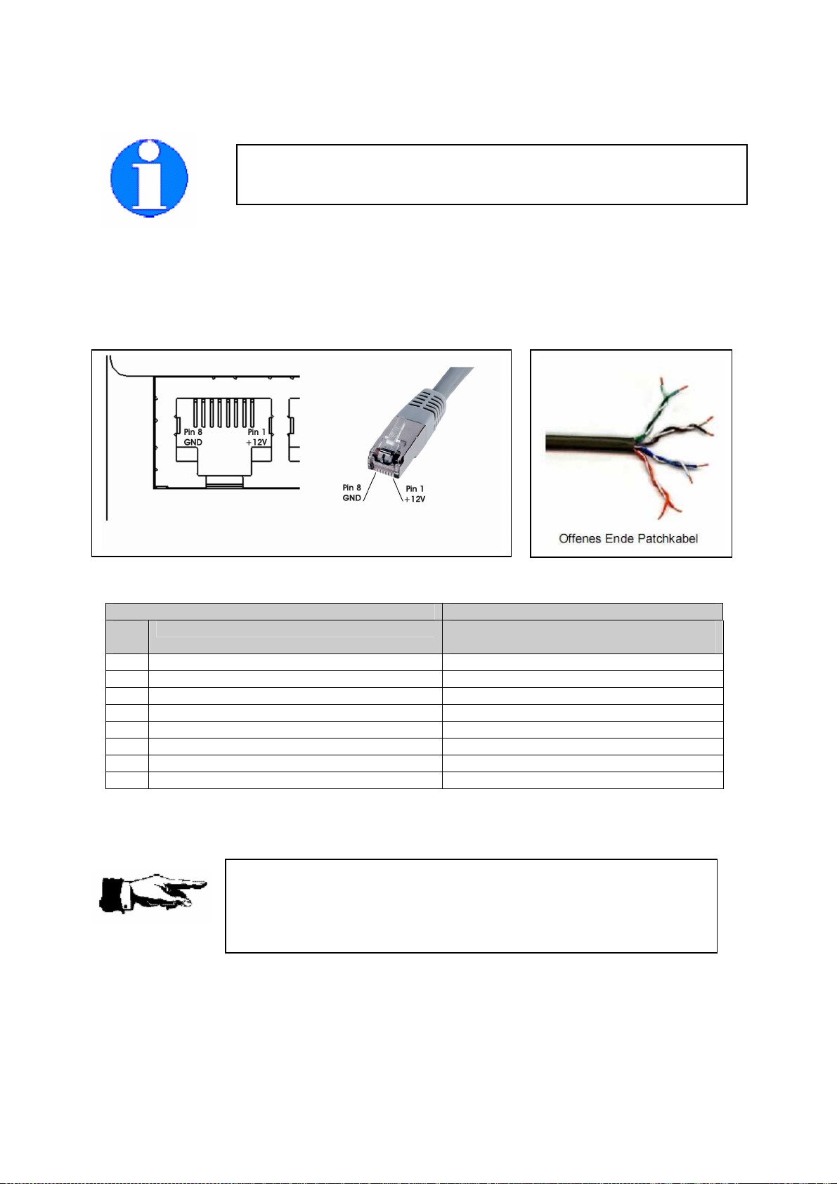
2.4.2.2. Pinout of the RJ-45 connectors
Remember, that the TX/RX lines of port 2 and port 3 (CDTI interfaces) are reversed to the IGC
standard. Pin 3 provides a 3.3V DC power supply for powering external FLARM displays. This makes
the interface compatible to existing external FLARM compatible displays.
Power can be supplied via each port. Be sure to power only FLARM and TRX-2000 via these lines to
prevent exceeding the maximum current.
Pinout Port 1
Pin
# Function Wire color of supplied connection
cable (acc. to EIA/TIA 568B)
1 + 9 - +28 V DC Brown
2 + 9 - +28 V DC Brown-White
3 n.c. (not connected) Green
4 n.c. (not connected) Blue-White
5 RX 1 (Data input 1) Blue
6 TX 1 (Data output 1) Green-White
7 GND Orange
8 GND Orange-white
It is recommended to power the TRX-2000 via port 1. Use the NMEA data provided on port 1 to feed
your Mode-S transponder for ADS-B out purposes. The baudrate can be set up using the TRX-Tool.
Pinbelegung RJ-45 Buchse
To prevent injury on the TRX-2000
and/or connected devices, always
check the pinout of the used connection cable.
Damages caused by reverse polarity or wrong connection are not covered
by the manufacturer's warranty.
The pinout complies
with the standards of the International Gliding
Commission (IGC) for flight recoders.
The pin numbering is reversed to the
industrial standard.

Garrecht Avionik GmbH TRX-2000 ADS-B Traffic Monitor User Manual
Revision: 1.0b 19 19 DEC 2011
Pinout Port 4
Pin #
Function
1 + 9 - +28 V DC
2 + 9 - +28 V DC
3 n.c. (not connected)
4 n.c. (not connected)
5 RX 4
6 TX 4
7 GND
8 GND
If the TRX-2000 comes without integral FLARM® module, an external FLARM® has to be connected for
proper operation. Connect your external FLARM® to port 4 to establish connection for power supply
and interfaces. Use a 1:1 RJ-45 patchcable (delivered with the TRX-2000)
Pin out port 2 and port 3 (CDTI 1, CDTI 2)
Pin out Port 2 and Port 3
Pin #
Function
1 + 9 - +28 V DC
2 + 9 - +28 V DC
3 3,3V Supply for external displays
4 GND
5 TX 2 / TX 3
6 RX 2 / RX 3
7 GND
8 GND
Connect existing CDTI to port 2 or port 3. 3.3V DC power will be supplied by the TRX-2000
Default settings port 2 and port 3:
Port 2: preconfigured for connecting external FLARM extended displays (Butterfly, FlymapL,
PDA with appropriate software
Port 3: preconfigured for connecting FLARM® Basic Displays (V2, V3, V4)
Default settings might be changed using the TRX-Tool.
Future firmware upgrades will make the TRX-1090 compatible to other display systems.
The TRX-Tool software checks periodically for new updates. Sending the unit to your dealer for
firmware upgrades is not required.
New information about firmware will be published on the manufacturers website.
www.garrecht.com

Garrecht Avionik GmbH TRX-2000 ADS-B Traffic Monitor User Manual
Revision: 1.0b 20 19 DEC 2011
2.4.3. Audio interface
The TRX-2000 comes with an audio interface to provide audible warnings additionally.
Electrical specifications:
Impedance: 8 Ohms
Voltage Level: appr. 3 V (VSS)
A small speaker can be connected directly to this interface. If the cockpit noise level is to high and if
using a headset, connecting the audio signal of the TRX-2000 to a audio panel or Line-in interface of a
radio or intercom is requried.
Refer to the radio’s or intercom’s installations manual for detailed information, how to hook up external
audio sources properly.
In some cases, connection of the TRX-2000 to your audio panel or Line-in interface of your radio
requires impedance matching.
Connecting a TRX-2000 to a Line-in interface:
•Use a voltage divider
Connecting a TRX-2000 to a avionic audio panel (Input Impedance: 500 Ohms)
Units with automatic impedance matching: direct connection (conceivably)
Unist without automatic impedance matching: Connection via impedance matching
transformer (i.e. Conrad Electronic P/N
515 952
Always consult the manuals before connecting the TRX-
2000 to avoid
damages to the units caused
by exceeding the maximum specified input
level
Consult your avionics workshop for addtional information.
Table of contents


