Gary Fisher CYBER COMPUTER User manual

Cyber
Cycling
Computer
Owners Manual
COMPUTER WARRANTY
Your Fisher Cyber Computer is guaranteed for
2 years against defects in workmanship or
materials. If you experience problems refer to
he suggestions in the troubleshooting guide in
his manual. If this does not solve your prob-
em, please return the computer to your
authorized Trek Dealer or send the computer
postage paid to:
Gary Fisher Bicycle Corporation
Attn. Computer Warranty Dept.
801 W Madison Street
Waterloo, WI 53594 USA
Please include the following:
1. The complete computer (wiring, etc.)
2. A copy of your sales receipt
3. A brief explanation of the problem
4. Your return address
For 2 years from the date of purchase, a
eplacement computer of the same model will
be sent to you postage paid by
Fisher Bicycle Corporation.
23
Cumulative
Odometer (ODO)
Stores your total
mileage for the year
in tenths of a mile
or km from 0 to
9999.9 and in full
miles or km from
10,000 to 99,999
Maximum Speed
(MAX)
Shows the fastest
speed you have
achieved during
your ride. The
Maximum speed
function of the
Cyber can be reset independently of the other
functions in the Cyber by holding the MODE
key for 2 seconds while the Maximum speed
is showing on the display. This feature is
excellent when you are doing sprint workouts.
Digital 12/24 hr CLOCK
Gives you the time of day in either 12 or 24
hour format.
Temperature
The Cyber is equipped with a temperature
sensor that gives you instantaneous tempera-
ture in either degrees Fahrenheit or Celsius
from -19-60o C or 2-140o F. The temperature
reading is tied to the calibration of the unit.
IntheUSmodethedisplaywillreadoutMiles,
Fahrenheit and 12 hour clock format. In the
European mode the display will read
Kilometers, Celsius and 24 hour clock format.
Auto Shut Down
Fisher computers will automatically shut-down
after 5-10 minutes of non-use to save battery
power. The Cyber will automatically restart as
soonastheunitreceivesinputfromthewheel.
FISHER OWNERS MANUAL
Congratulations and Thank you for purchasing
he Fisher Cyber Bicycling Computer! The New
Fisher Cyber with Workout Window (patent
pending) represents the latest in Bicycle com-
puter technology and concept. The Workout
Window feature can greatly enhance the rid-
ng experience of any cyclist, whether they
are a recreational rider or a top notch racer.
The Cyber with Workout Window may actually
change the way you ride your bicycle!
Please read this instruction manual carefully
and save this manual for future reference.
Precautions
Remember to watch the road while riding.
Watching your bicycle computer makes it diffi-
cult to see upcoming obstacles. Awareness of
potential road, trial, or traffic problems should
be your main concern.
DEFINITION OF FUNCTIONS
Speedometer
(miles or kilome-
ters) (SPD)
(M/hr or KM/hr)
Tells you your
instantaneous
speed. Accurate to
0.1 mph or Kmph
Automatic Ride Time Stopwatch (STP)
Stopwatch that starts and stops when your
wheel is turning. Records your time actually
spent riding, up to 9:59:59
Trip Odometer
(DST)
Tells you the
distance for your
current ride from 0
to 999.99 mi.
or km.
Average Speed
(AVS)
Your average speed
calculated using
your true ride time
and trip distance
Average Speed Comparison (▲or ▼)
Compares current speed to average speed. As
you are riding, a (▲) or (▼) will appear in
the top right hand corner of the display. This
will indicate whether your current speed is
faster (▲) or slower (▼) than your current
average speed. This function is automatic,
requires no programming and cannot
be disabled
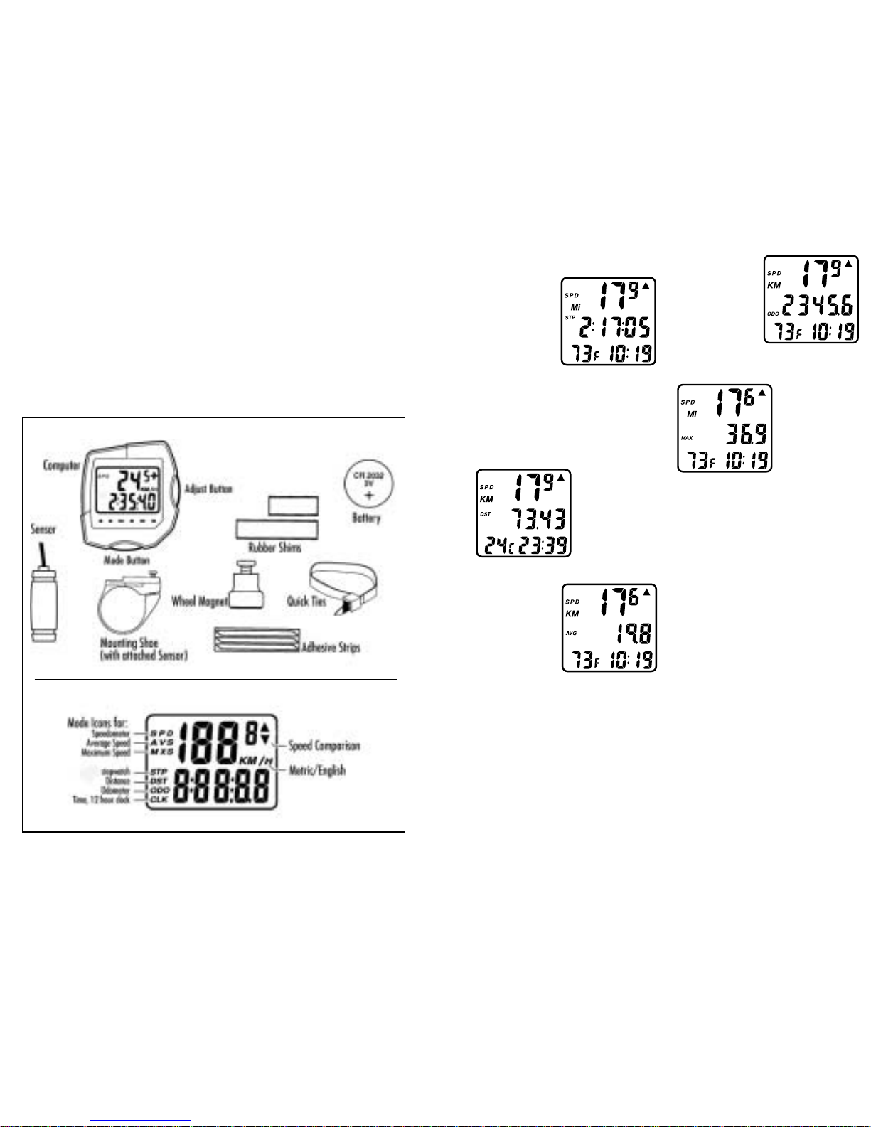
PARTS LIST
CYBER LCD SCREEN
SPD/DST
SPD/AVG
SPD/ODO
SPD/MAX
SPD/STP

45
Attach the sensor to the fork blade with the
quick ties but do not tighten the ties completely
until final adjustment is complete.
2. Attach the wheel magnet to a spoke,
aligning the magnet with the sensor so it faces
and intersects the bottom polished line on the
sensor. The magnet should have 1-2 mm
clearance from the sensor. If the sensor and
magnet are too close or touching, rotate the
sensor unit toward the back of the fork blade
until adequate clearance is achieved. Carefully
tighten the quick ties making sure you main-
tain the proper space between the magnet
and the sensor. Trim the excess quick tie strap
using a scissors or fingernail clipper. Tighten
the magnet screw, but be careful not to over
tighten as this can damage the fitting.
Sensor Wiring and Bracket
1. Position the sensor unit to the inside of
either the right of left fork blade anywhere
from 3-6 inches up from the fork blade tip.
1. Remove the battery cover from the back
side of the computer using a narrow flat
blade screwdriver.
2. Install the battery so that the positive "+"
side of the battery is visible, and replace the
battery cover.
CAUTION: On the bottom of the computer
head next to the battery door is a small
recessed button. This is the Auto Clear Button.
Pressing this button will clear all memories
and reset all functions to their default values.
Workout Window
The CYBER is equipped with Fisher’s patented
Workout Window™ feature. The
Workout Window is a “computer within
your computer” that allows you to record a
second set of ride information (Speed,
Average Speed, Distance etc.) independent
from the normal operating modes. The
Workout Window allows you to easily sep-
arate the information for a race from the
information for your total ride so that you can
have an accurate picture of your racing or
training intensity.
TheWorkout
Window is easily
accessible from any
of the Cyber’s main
operating screens
simply by pressing
the Workout
Window Button.
NSTALLATION
Sensor and Wheel Magnet
2. Wind the wire upward around the front
brake cable until the wire is adjacent to the
handlebar, allowing enough slack for free
movement of the steering assembly cables.
3. Attach the bracket to the handlebar on
either side of the stem. The bracket goes onto
the handlebar with the wire toward the rider
side of the bar. Use the appropriate rubber
shim between the bracket and handlebar to
provide a secure fit.
The Fisher Cyber Computer attaches to the
mounting bracket by sliding the unit onto the
bracket from the back until it snaps firmly
into position. To remove the computer from
the bracket, place your thumb against the
back of the mounting bracket and pull the
computer toward you with your index finger.
1. Route the sensor wire up the back of the
fork blade or wind the wire around the blade,
making sure that the wire is not loose and
that you leave enough wire to reach the han-
dlebar. Secure the wire to the fork blade
immediately above the sensor and at the top
of the fork blade, using the adhesive strips
that are provided or electrical tape.
COMPUTER SET UP
Battery Installation
Shims will
prevent slipping
Attaching the Computer to the Bracket

67
The Cyber is equipped with 3 buttons that con-
rol the functions of the unit:
1. MODE
Changes the Main Screens of the Cyber
2. WORKOUT WINDOW
Enters and Exit’s the Workout Window
3. START/STOP
Starts and stops the Stopwatch in the Workout
Window and adjusts the digits when setting
he Clock, Wheel Size and Odometers.
PROGRAMMING YOUR FISHER CYBER
CYCLE COMPUTER
We will now begin to program the features of
he Cyber. Take a few minutes to familiarize
yourself the operation of the buttons and how
he Cyber operates before proceeding.
Quick Escape Feature
At any time during the programming of the
Cyber simply press and hold the MODE key
for 1 second to store all information up to
hat point in memory and return to the
main screen.
Setting the Clock, Thermometer and
Miles or Kilometers
1. In the SPD/STP
screen, press and
hold the MODE key
for 2 seconds.
2. The screen will
clear and Mi, F
and 12 will appear
indicating the American calibration settings.
3. Press the START/STOP key to change to
the Metric settings if desired, or press the
MODE key to set screen and advance to
Adjusting the Clock
4. The Hours digits will appear and begin to
flash. Advance the Hours by pressing the
START/STOP key. NOTE: Holding the
START/STOP key will fast advance the digits.
5. Press the MODE key to set the screen and
advance to setting the Minutes in the same
manner as Hours.
6. Press the MODE key one final time to set
the screen and return to the main screen .
Wheel Size Setting
The wheel size setting number is equal to the
distance, in millimeters, that your front wheel
travels during one complete revolution. Each
time the wheel magnet passes the sensor unit
on your fork, the sensor sends an impulse to
the computer telling it that your wheel has
completed one revolution. The computer cal-
culates this distance vs. time to give you accu-
rate readings for the various modes.
Determining Wheel Size Setting
There are three methods for determining the
wheel size setting. For the most accurate
computer readings, it is best to measure the
actual distance that your wheel travels in one
complete revolution. This method is called a
wheel roll out.
Method One: Wheel Roll Out
• Perform the wheel roll out on a hard, flat,
smooth surface such as a garage or
basement floor.
• Make sure your tires are properly inflated.
1. Position your bike so that the valve stem of
the front wheel is at its bottom most position.
Mark the spot on the floor directly under the
center of the valve stem using a piece of tape
or chalk.
2. Roll thebicycleforward inastraight line,
whileputting downwardpressure onthe handle-
barsto simulaterider weight.When thewheel
hascompleted onerevolution andthe valvestem
isat itsbottom position,mark thefloor directly
underthe centerof thevalve stemwith tapeor
chalk.Measure thedistance betweenthe two
marksin millimeters.(Note: Conversionof in.to
mm.is 1in.=25.4 mm.)This isyour wheelset-
tingnumber.Youcan repeatthis procedureand
averageyour results.Werecommend that you
recordyour wheelsetting numbershere for
futurereference.
Method Two:
Measure wheel radius (including tire) in
mm and multiply by 6.2832=Wheel
setting number.
Method Three:
Refer to the following chart and input the
number that corresponds to your tire size.
(Note: Actual size of two similarly marked
tires from different manufactures can vary
significantly, making this method the least
accurate.)
WHEEL SIZE CHART
Wheel/Tire Size Wheel Size Setting in mm
26 x 1.0 ATB . . . . . . . . .1913
26 x 1.25 . . . . . . . . . . .1953
26 x 1.5 . . . . . . . . . . . .1985
26 x 1.9 . . . . . . . . . . . .2055
26 x 2.0 . . . . . . . . . . . .2074
26 x 2.1 . . . . . . . . . . . .2095
26 x 2.2 . . . . . . . . . . . .2110
700 x 20c . . . . . . . . . . . .2074
700 x 23c . . . . . . . . . . . .2114
700 x 25c . . . . . . . . . . . .2124
700 x 28c . . . . . . . . . . . .2140
700 x 32c . . . . . . . . . . . .2155
700 x 35c . . . . . . . . . . . .2175
700 x 38c . . . . . . . . . . . .2180
700 x 40c . . . . . . . . . . . .2190
650 x 20c . . . . . . . . . . . .1945
650 x 23c . . . . . . . . . . . .1990
Wide 700c Tubular . . . . . . . . . .2117
Narrow 700c Tubular . . . . . . . .2105
27 x 1” . . . . . . . . . . . . .2145
27 x 1-1/4 . . . . . . . . . .2160
ATB
ROAD
89
OPERATING THE WORKOUT WINDOW
The Cyber is equipped with Fisher’s patented
computer within a computer, the Workout
Window. The Workout Window allows you to
track the intensity portions of your ride
separately from the information for the
whole ride.
The revolutionary Workout Window feature
was developed to make your riding
experience—
SAFER
No need to compromise traffic laws to
enhance your average speed. Ride safely
through traffic knowing that you can start the
Workout Window when you reach the
open road.
HEALTHIER
No need to skip a proper warm up and cool
down to enhance your average speed. Start
your Workout Window after your warm up
and stop it before your cool down.
MORE ENJOYABLE
No need to accept a compromised average
speed. The Workout Window can be a real
motivator by showing you your true average
speed when you have the “Hammer Down”.
MORE PRODUCTIVE
Use the Workout window to track your per-
formance while ridding your favorite course,
during intervals, time trials, or even sprints.
Get the feedback you need without losing
your cumulative riding data.
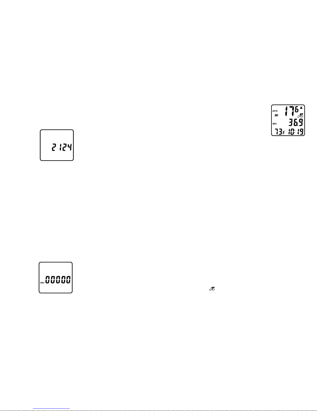
Entering the Workout Window
Press the WORKOUT WINDOW key from any
main screen to enter the Workout Window.
The Workout Window Icon ( ) will appear
on the right hand side of the screen.
Activating the Workout Window
To activate the
Workout Window
you must press the
START/STOP key in
the Workout
Window SPD/STP
screen to start the
Stopwatch. Once
the START/STOP key is pressed the action of
the Stopwatch is automatic, starting and stop-
ping when the wheel of the bike is turning. To
stop the Workout Window you must press the
START/STOP key again. The Workout Window
icon will flash to indicate that the Workout
Window is operating.
Clearing the Workout Window
1. Pressing the START/STOP key for 2 sec-
onds in the main SPD/STP screen will reset all
functions, both main and Workout Window
2. Pressing the START/STOP key for 2 sec-
onds in the WORKOUT WINDOW SPD/STP
screen will reset only the WORKOUT WINDOW
functions and will not affect the Normal
Operating functions.
3. Resetting Maximum Speed –Just as
in the Normal operating mode. If you are
doing sprint workouts, the Workout Window
maximum speed of the Cyber can be reset
independent of the other WORKOUT WINDOW
functions by pressing and holding the MODE
keyfortwoseconds while intheSPD/MAX screen.
Setting Wheel Size
1. With the Cyber in the SPD/ODO screen,
press and hold the MODE key for 2 seconds.
The screen will clear and the default wheel
size (2124 700 x 25c) will appear with the
first digit flashing.
2. Use the
START/STOP key to
advance to the
correct number for
your wheel size.
3. Press the MODE
key to set and
advance to the next digit.
4. Repeat until all digits are programmed.
5. Pressingthe MODEkey thelast timewill
advancethe unitto programmingthe Odometer.
Setting the Programmable Odometer
The Cyber is equipped with separate
Programmable Odometers for both the main
functions and the Workout Window. The
Programmable Odometer allows you to
re-enter your computers last mileage back
into memory after a battery change.
NOTE: Remember to write down the mileage
of both the Main Odometer and Workout
Window Odometer before you change the bat-
tery in the unit.
1. Entering the main Programmable
Odometer happens automatically after you
have finished
setting the wheel
size. The screen
will clear and 5
zeros will appear
with the first digit
flashing.
2. Usethe START/STOPand MODE keys to
advanceand setthe digitsin thesame manneras
youdid withthe clockand wheelsize.
3. WhenyoupresstheMODEkeyforthelasttime
theunitwillreturntothemainSPD/ODOwindow.
4. Toskip theprocedure forsetting thepro-
grammableodometer pressand holdthe MODE
keyfor onesecond.
TO SET THE PROGRAMMABLE ODOMETER
IN THE WORKOUT WINDOW
1. Pressand Holdthe MODEkey for2 seconds
whilein theWorkoutWindow SPD/ODO screen.
2. Thescreen willclear and5 zeroswill appear
withthe firstdigit flashing.Use theSTART/STOP
andMODE keysto advanceand setthe digitsin
thesame manneras youdid withthe clockand
wheelsize.
3. Whenyou pressthe MODEkey forthe last
timethe unitwill returnto theWorkoutWindow
SPD/ODOScreen.
OPERATION OF THE MAIN CYBER FUNCTIONS
Theoperationof the main functions of the Fisher
Cybercyclecomputer is mostly automatic. The stop-
watchturnson and off automatically when the wheel
turns. Average andMaximumspeedsareautomati-
callycalculatedusing the ride time stopwatch.
Resetting the Main Functions
Resetthe stopwatchby pressingand holdingthe
START/STOPfor 2 seconds while in the SPD/STP
screen.This actionalso clearsAverageSpeed,
MaximumSpeed andTripDistance, aswell as
allof theWorkoutWindow functions to zero.
Resetting Maximum Speed
Ifyou aredoing sprintworkouts, theMaximum
Speedof theCyber canbe resetindependent of
theother functionsby pressingand holdingthe
MODEkey fortwo secondswhile inthe Maximum
Speedscreen.

10 11
Desired Function Which Key to Press Notes
Advance Digits While Programming Start/Stop Hold for Fast Advance
Set Digits While Programming Mode
Escape From Programming Mode Mode for 1 Sec
Set Clock, Thermometer and Units Mode for 2 Sec In SPD/STP Screen
Set Wheel Size Mode for 2 Sec In SPD/ODO Screen
Main Programmable ODO Automatic at end of
Wheel Size Setting
Reset All Functions Start/Stop for 2 Sec In SPD/STP Screen
Reset Main Max Speed Only Mode for 2 Sec In SPD/MAX Screen
Enter Workout Window Workout window In any Screen
Workout Window Programmable ODO Mode for 2 sec In Workout Window SPD/ODO
Screen
Start Workout Window Start Stop while in Initial start only, subsequent
Workout Window starts and stops are automatic
Reset only Workout Window Start/Stop for 2 Sec In Workout Window SPD/STP
Functions Screen
Reset only Workout Window Mode for 2 Sec In Workout Window SPD/MAX
Max Speed Screen
TROUBLESHOOTING GUIDE
Problem
Solution
No speedometer reading
Check for proper magnet sensor alignment. Check computer to
make sure it is snapped firmly into the bracket.
Display Readout Fades
Poor battery contact or dead battery-remove the battery, check
contactor replace battery.
Display shows irregular figures
Press A/C button on the back of the unit to clear and restart
the computer.
MX display reads 99.5
Clear modes by pressing BOTH buttons in regular mode for 1 sec
ond, check wheel magnet/sensor alignment.
Slow display response
Temperature outside of computer operating limits 32–120˚F
(0–49˚C)
Black display
Computer unit too hot or display exposed to direct sunlight for too
long. Let the unit cool and it should return to normal.
Table of contents
Popular Bicycle Accessories manuals by other brands


topmove
topmove 271491 Instructions for use

Dremefa
Dremefa Bobike Junior operating instructions

Electric Bike Outfitters
Electric Bike Outfitters KT-LCD3 user manual

Ergon
Ergon SM3 Installation and user instructions

InStep
InStep Single Seat Bicycle Trailer user manual

SKS Germany
SKS Germany COMPIT instruction manual