STEP 2:
Assemble the L-Brackets (3.) to the Clamps using the supplied
M5 x 18mm bolts (6.). Maximum torque setting of 5Nm.
NOTE: There are 2 holes for adjustment of the l-bracket height.
Select the preferred height based on handlebar / stem setup on the bike.
STEP 5:
Repeat the above steps 1 ~ 4 for the
opposite side.
NOTE: Both left and right need to be positioned
at the same height on the L-bracket adjustment.
Check to make sure the cups will clear the top
of the handlebar and are also positioned in
the same holes and at the same angle on the
L-bracket.
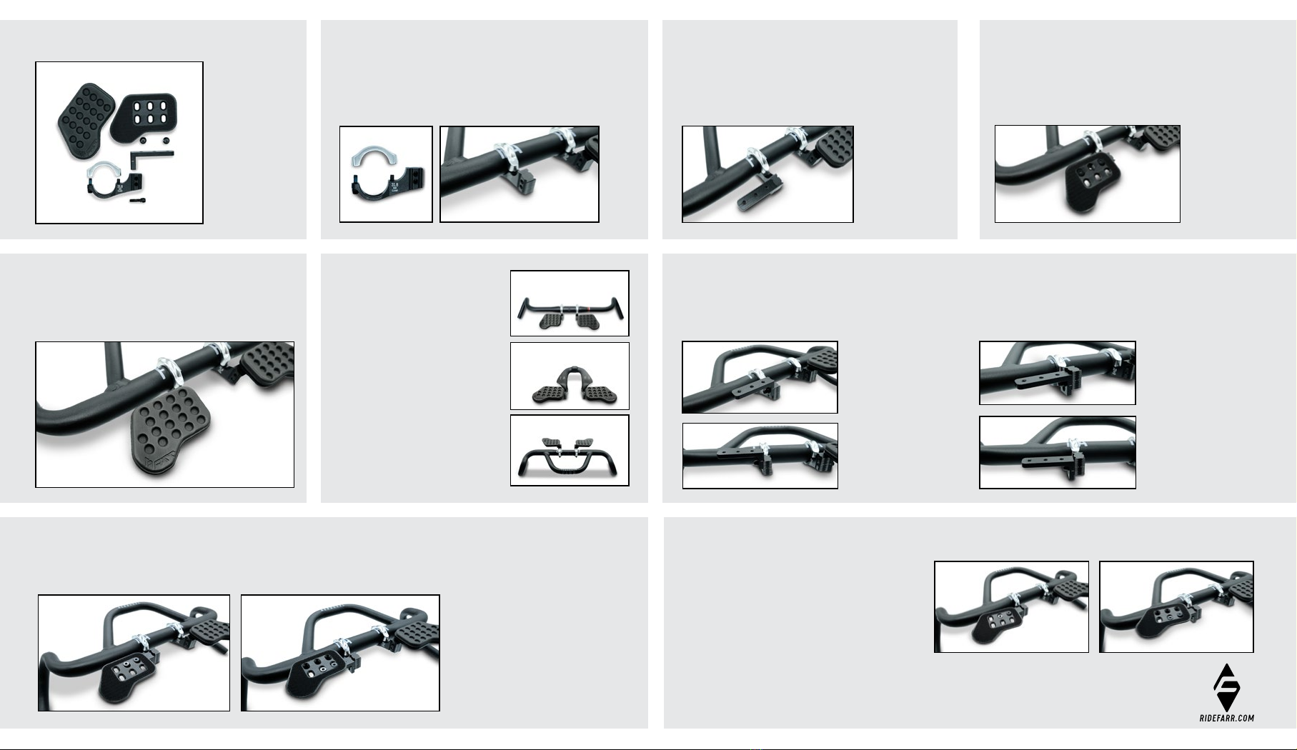
FINAL ASSEMBLY OVERVIEW:
There are 3 common handlebar setups
that we foresee the arm rest kit being
used for. To the right are the 3 examples:
OVERVIEW OF PARTS:
STEP 4:
Apply the pad (1.) to the top of the cup (2.). Ideal position of the pad
is centered so the slight overlap on the edges is uniform around
the alloy cup. This will ensure the most comfort and durability of
the pad material.
STEP 3:
Attach the cups (2.) supplied in the required position. We recommend
using the front row of holes as this allows the best weight distribution
and also the neatest setup for most common bike setups. The cups
can be positioned inward or outward via the 3 different holes and can
also be adjusted in the horizonal plane via the angled chamfer holes.
ADJUSTMENT OPTIONS:
Given the variety of adjustment options available with the design, below are some of the key aspects of ensuring a comfortable fit and setup
on your bike.
1. HEIGHT OF L-BRACKET ON LOWER CLAMP
2. POSITION OF CUP FORE/AFT ON THE L-BRACKET 3. ANGLE POSITION OF CUP INWARD/OUTWARD ON THE L-BRACKET
L-bracket in the lower
position. This is a more
ideal position based on
our feedback and allows
the pad to be positioned
lower and in a more
“natural” resting position
for your forearms.
Cup (2.) can be positioned in the first or second row of holes. We recommend the first row as it ensures the cups are positioned slightly behind the
handlebar. The second row option would allow the cup to clear the handlebar if the L-bracket was in the higher position on the clamp.
Due to the chamfered holes and counter sunk bolts, the cup
can also be adjusted both inward and outward in terms of the
angle in the horizontal plane. The photos to the right both show
the cup in the inward angle position, with the cup in either the
first row ( left ) or second row hole ( right ).
Please experiment with your optimal setup and only tighten
up the necessary hardware once both clamps are aligned and
positioned correctly to ensure comfort.
The above information is provided purely as a reference and
there are infinite options for how to set the arm rest kit up on
your personal bike.
L-bracket in the higher
position. This positions
the pad above the top of
most base handlebars.
31.8 Drop/MTB bar
Aero Bolt-On Combo
Aero Gravel Combo
(3.)
(2.)
(8.)
(1.)
(1.) ARM REST KIT
(2.) ARM REST CUP
(LEFT & RIGHT)
(3.) L-BRACKET
(4.) LOWER CLAMPS
(5.) BOLT M5 x 9mm
(6.) BOLT T25 M5 x 18mm
(7.) BOLT T25 M5 x 16mm
(8.) TOP CLAMP
(2.)
(3.)
(5.)
(6.)
(7.)
(2.) (2.)
STEP 1:
Fit the top clamp (8.) and lower clamp (4.) to the 31.8mm handlebar.
Bolts (7.) must be torqued to a maximum of 5Nm.
(7.)
(8.)
(4.)
NOTE: If using the carbon/alloy aero bolt-on then the top clamps are substituted with
the top half of the aero bolt-on and the M5 x 16mm bolts must be used to clamp the unit.
Follow the torque setting for the respective aero bolt-on.
NOTE: The cup can also be moved inward or outward
along the 3 different positions on the L-bracket.


