Gas Data GFM600 User manual

GAS DATA
Monitoring the Environment
GFM600 Velocity
Monitor User Manual

D O C U M E N T C O N T R O L S H E E T
GFM600 Velocity Monitor User Manual
Issue A, Revision 0 Issue Date: April 9, 2007
Copy No: 1 Copy Holder: Archive
User guide to the operation of the GFM600 portable
Velocity monitor.
Issue Description:
New manual - February 2007.
Revision Description:
First release - for proof checking.
©
Gas Data
Pegasus House, Wheler Road, Seven Stars Estate, Coventry CV3 4LB, United Kingdom
Phone +44 (0)24 7630 3311 • Fax +44 (0)24 7630 7711
GFM600 GFM600 Velocity Monitor User Manual

Table of Contents
Introduction
1
General handling tips 17
Warranty policy
1
Conditions and exclusions
1
Safe use of the GFM600 Velocity
Monitor
2
Safe practice
2
Important safety related points
2
In the case
3
Operation
4
Connections
4
Gas velocity measurement
5
Auto Turn Off 6
Maintenance
7
Low Battery warning
7
Batteries 7
Factory calibration
8
Technical Specification 9
Conversion charts 10
Understanding instruments for use in
flammable atmospheres 13
Hazardous areas classified by zones 13
Different gas types. 13
Design and construction of
intrinsically safe instruments for use
in flammable atmospheres. 14
Testing and certification 15
Schiltknect Vane Anemometer 16
Operating Instructions 16
Important notes 16
Response Time 17
Technical data –MiniAir 6 Micro 17
Cleaning and maintenance 17
i

G F M 6 0 0 U S E R M A N U A L
Introduction
The Gas Data GFM600 is designed
specifically for measuring gas
velocity in a variety of applications.
Operation is extremely simple, yet
the readings obtained are highly
accurate. The instrument uses a
plug-in vane anemometer to
measure gas velocity and provides a
digital read-out of velocity in ms-1.
The GFM600 has rechargeable
Nickel Metal Hydride batteries
giving around twenty hours use
between charges. A battery charger
and mains unit is supplied with the
instrument and a field replaceable
battery pack is also available as an
optional extra.
Warranty policy
This instrument is guaranteed, to the original end user purchaser, against defects in
materials and workmanship for a period of one year from the date of shipment to
the user. During this period, Gas Data Limited will repair or replace defective parts
on an exchange basis. Freight charged to and from the Gas Data factory or
authorised service centre will be paid by the end user. The decision to repair or
replace will be determined by Gas Data Limited.
Conditions and exclusions
To maintain this warranty, the purchaser must perform maintenance and
calibration as prescribed in this user guide. This includes prompt replacement or
repair of defective parts and such other necessary maintenance, calibration and
repair as may be required according to the use of the equipment in the reasonable
judgement of Gas Data Limited.
Normal wear and tear, and parts damaged by abuse, misuse, negligence or accidents
are specifically excluded from the warranty.
GFM600 - 1 - GFM600 Velocity Monitor User Manual

G F M 6 0 0 U S E R M A N U A L
Safe use of the GFM600 Velocity Monitor
The Gas Data GFM600 Velocity Monitor has been designed to operate in typical
field environments where flammable gases may be present. The following points
should be observed.
Safe practice
•
BEFORE entering a known hazardous zone, switch on the instrument and
make sure the display is visible.
•
BEFORE entering a known hazardous zone, check that the keys respond.
Important safety related points
•
Use only Gas Data spares and accessories.
•
Do not operate the GFM600 Velocity Monitor in ambient temperatures
outside the range of -10 to +40C.
•
Do not attempt to dismantle the instrument. It contains no user replaceable
parts.
•
Do not operate the unit if it is damaged in any way (i.e. loose front panel,
missing screws etc.).
•
Do not connect or remove plugs from the battery charger socket in the
hazardous area.
•
Only charge the batteries in a safe well-ventilated area using the charger
supplied.
IMPORTANT - The GFM600 Monitor Series is not infallible. As the usage
of the instrument is beyond Gas Data’s control, Gas Data cannot accept any
liability for loss or damage due to its usage. Satisfy yourself that the unit is
suitable for the application that you intend to use it for. If in doubt about the
suitability of a GFM600 Velocity Monitor instrument for a particular
application call Gas Data for further advice.
GFM600 - 2 - GFM600 Velocity Monitor User Manual

G F M 6 0 0 U S E R M A N U A L
In the case
The GFM600 instruments are supplied in a fitted case containing the following
items:
GFM600 instrument
Vane
anemometer
Battery charger
GFM600 - 3 - GFM600 Velocity Monitor User Manual

G F M 6 0 0 U S E R M A N U A L
Operation
1. This key allows you to switch the backlight
on or off.
2. Not used.
3. This key allows you to start the sample.
4. This buttons allows you to move to the velocity
screen.
5. Power ON/OFF. This key simply toggles the
instrument on or off. Under battery power, the
instrument will automatically turn itself
off if no key is pressed for 10 minutes. The
instrument backlight can be switched on at
anytime during the sampling process.
Connections
Communications/anemometer port
Battery
charger socket
GFM600 - 4 - GFM600 Velocity Monitor User Manual
Section
1
G F M 6 0 0 U S E R M A N U A L
Gas velocity measurement
IMPORTANT
Schiltknect anemometers do not form part of the ATEX certification of the
Gas Data GFM series. Contact Gas Data for further advice on the safe use of
these probes.
Before attempting to measure gas velocity, make sure that the vane
anemometer is long enough to reach the centre of the pipe through which
the gas is flowing.
Connect the vane anemometer to the Communications/Anemometer port on the
top end of the instrument case.
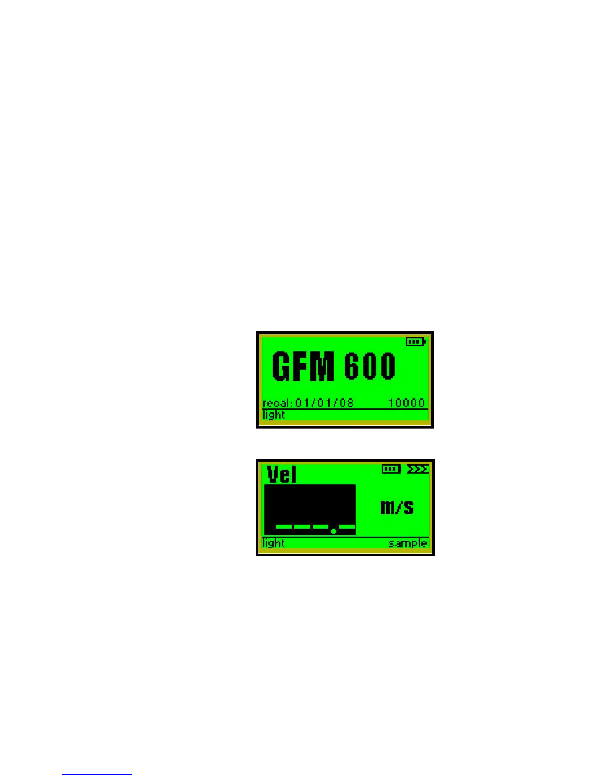
After you have switched the instrument on, the display screen will first show the
start-up banner, which contains details of the instrument model, serial number and
recalibration date. A battery condition indicator at the top right-hand side of the
screen informs you about the state of charge of the battery.
Press the right arrow to continue to the velocity screen.
GFM600 - 5 - GFM600 Velocity Monitor User Manual

G F M 6 0 0 U S E R M A N U A L
Locate a suitable gland or bung on the
pipework and insert the vane anemometer,
taking care to ensure that the anemometer is
correctly orientated. The arrow on the tip of
the anemometer should be in line with the
pipe, NOT at right angles to it. When the
anemometer is as far into the gland as
possible, without opening the tap, re-check
the orientation and open the gas tap. Finally,
push the anemometer into the gland far
enough to ensure that the vane head is in
the centre of the gas pipe.
The display screen will change to show the
last retained gas velocity reading indicated
by the highlight around the velocity figure.
Now press the ‘sample’key. The instrument will now measure the velocity of the
gas flowing through the pipework
.
When the reading has stabilised, press the ‘sample’key again to retain the reading.
This will return the highlight area around the velocity figure.
Carefully remove the vane anemometer from the gland on the gas pipe, pausing to
turn off the gas tap before removing it completely.
This completes the measurement.
Auto Turn Off
To help conserve battery life, the GFM600 instrument features an auto power off
facility. This ensures that the instrument will switch itself off after 10 minutes if no
keys are pressed.
- 6 - GFM600 Velocity Monitor User Manual
Take great care
when inserting the
anemometer to
avoid gas leakage
.
Take great care
when removing the
anemometer
. In
particular, avoid
standing with your
face in direct line
with the gland
because gas can
be expelled at
great force.
GFM600

G F M 6 0 0 U S E R M A N U A L
Section
2
Maintenance
Low Battery warning
A series of vertical bars at the top right-hand side of the display screen indicates the
state of charge of the rechargeable batteries.
When there is a single bar of battery life left, it is time to recharge the batteries or
replace them with another battery pack. If the batteries become completely
exhausted the single bar of battery life will flash and then the instrument will
automatically switch off. Make sure the batteries receive a full recharge.
To recharge the batteries, simply plug in
the battery charger lead to the socket on
the top end of the instrument and plug
the charger into the mains. The batteries
will be fully charged in about three
hours.
Batteries
The GFM600 Series uses rechargeable Nickel
Metal Hydride cells.
To change the batteries, remove the two screws on
the rear of the instrument, then lift the battery
cover and remove the battery pack from the recess.
Place the new battery pack in the recess, making
sure that the metal contacts on the battery pack are
placed face down on the spring contacts in the
base of the battery box. Replace the battery cover
and secure with the two screws.
Always replace the battery pack in dry, clean
conditions, preferably indoors. NEVER allow
dust or moisture to enter the battery compartment.
GFM600 - 7 - GFM600 Velocity Monitor User Manual

G F M 6 0 0 U S E R M A N U A L
Do not use excessive force on the battery cover fixing screws.
Make sure the rubber seal is correctly in place.
If you replace the batteries in the field, you can, of course, recharge them later
when you return to base.
If the instrument is to be stored for more than four weeks, ensure that the batteries
are fully charged. After four weeks, charge the batteries again.
However, if the instrument does not operate after prolonged storage, the batteries
have become discharged and will be unable to ‘fast charge’. They will, therefore,
need a longer charge time.
Factory calibration
The instrument is not supplied with a calibration certificate. The instrument is
supplied with a functional check sheet.
It is recommended that the instrument be returned to Gas Data Limited once every
five years for a general inspection.
GFM600 - 8 - GFM600 Velocity Monitor User Manual

G F M 6 0 0 U S E R M A N U A L
Appendix
A
Technical Specification
GFM600 - 9 - GFM600 Velocity Monitor User Manual
Range
Vane anemometer
12mm diameter x
340mm long.
0-40 m/s
Size
200mm x 90mm x 50mm
approx
Weight
400g (approx.)
Battery type
Rechargeable Nickel metal
hydride
Battery run time
>18 hours (backlight off)
G F M 6 0 0 U S E R M A N U A L
Appendix
B
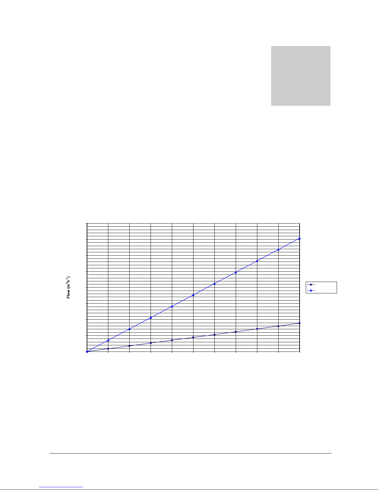
Conversion charts
The following charts are included to enable you to make quick and easy
conversions from velocity measurements provided by the vane anemometer to
flow rates.
Velocity - Flow conversion chart
160.00
140.00
120.00
100.00
80.00
60.00
40.00
20.00
0.00 0 0.5 1 1.5 2 2.5 3 3.5 4 4.5 5
Velocity (ms-1)
GFM600 - 10 - GFM600 Velocity Monitor User Manual
d = 50mm
d = 100mm

G F M 6 0 0 U S E R M A N U A L
Velocity - Flow conversion chart
600.00
500.00
400.00
300.00
200.00
100.00
0.00 0 0.5 1 1.5 2 2.5 3 3.5 4 4.5 5
Velocity (ms-1)
Velocity - Flow conversion chart
6000.00
5000.00
4000.00
3000.00
2000.00
1000.00
0.00 0 5 10 15 20 25 30 35 40
Velocity (ms-1)
GFM600 - 11 - GFM600 Velocity Monitor User Manual
d = 50mm
d = 100mm
d = 150mm
d = 180mm
d = 220mm
d = 250mm
d = 300mm
d = 50mm
d = 100mm
d = 150mm
d = 180mm
d = 220mm
d = 250mm
d = 300mm

G F M 6 0 0 U S E R M A N U A L
The formula for calculating the conversion is:
f =0.00283d v
where f = flow in m3h-1
d = pipe inside diameter in mm
v = velocity in ms-1
GFM600 - 12 - GFM600 Velocity Monitor User Manual
2

G F M 6 0 0 U S E R M A N U A L
Appendix
C
Understanding
instruments for use in
flammable atmospheres
Hazardous areas classified by zones
There are three zones defined to guide users as to the necessary precautions, which
should be taken when working in potentially flammable atmospheres:
1. Zone 0 - An area in which an explosive gas/air mixture is continuously
present, or present for long periods.
2. Zone 1 - An area in which an explosive gas/air mixture is likely to occur in
normal operation.
3. Zone 2 - An area in which an explosive gas/air mixture is not likely to
occur in normal operation and if it does occur will exist only for a short time.
Make certain that the area in which you intend to work can be described by one of
the zones above. THE GFM600 SERIES IS SUITABLE FOR USE IN
ZONE 1 AND ZONE 2.
Different gas types.
Different gases are grouped according to how easily they are ignited. Some
examples are given below. (For other gases please contact Gas Data).
GFM600 - 13 - GFM600 Velocity Monitor User Manual
Gas
Relative Ignition
Group
Hydrogen/Acetylene
Most easily ignited
IIC
Ethylene
IIB
Carbon monoxide
IIB
Hydrogen sulphide
IIB
Ammonia
IIA
Propane
IIA

G F M 6 0 0 U S E R M A N U A L
THE GFM600 SERIES IS SUITABLE FOR USE IN FLAMMABLE
ATMOSPHERES CAUSED BY THE PRESENCE OF GASES IN
GROUP I, GROUP IIA AND GROUP IIB.
Design and construction of intrinsically safe instruments for use in
flammable atmospheres
.
The technique of intrinsically safe design and construction is defined in the
European Standard EN50020:1995. The technique identifies potential sources of
ignition (by spark or by heat) and specifies the design of safety circuits that limit the
energy of the spark and/or the component temperatures such that they cannot
ignite the gases expected within the hazardous area. There are two categories if
intrinsically safe instruments;
1. ‘ia’ The safety circuits used will prevent the generation of a spark or
temperature capable of igniting the gas even if the instrument develops TWO
faults.
2. ‘ib’The safety circuits used will prevent the generation of a spark or
temperature cable of igniting the gas even if the instrument develops ONE fault.
THE GFM600 SERIES IS DESIGNED TO MEET THE
REQUIREMENTS OF CATEGORY ‘ib’.
By testing components in fault conditions (as required by ‘ib’) the worst case
temperature within the instrument is determined. This is used to give the
instrument a temperature classification. A guide to temperature classifications is
given below.
The higher the T class the lower the temperature.
Different gases will be ignited at different temperatures. Some examples are given
below.
GFM600 - 14 - GFM600 Velocity Monitor User Manual
Petrol vapour
IIA
Methane
Least easily ignited
I
Temperature Class
Maximum Temperature (C)
T1
450
T2
300
T3
200
T4
135
T5
100
T6
85

G F M 6 0 0 U S E R M A N U A L
THE GFM600 SERIES IS DESIGNED TO MEET THE
REQUIREMENTS OF CLASS T1.
Testing and certification
The GFM600 Series has been submitted for European Type Assessment. This
assessment examines the design and construction criteria set out above and
controls the manufacture. This process is defined in Annex II of the European
ATEX Directive 94/9/EC. This allows the instrument to carry the ‘Ex’logo
followed by a summary of the level of protection that is incorporated into the
instrument.
GFM600 - 15 - GFM600 Velocity Monitor User Manual
Gas
MINIMUM Required T class
Acetylene
T2
Hydrogen
T1
Ethylene
T2
Carbon monoxide
T1
Hydrogen sulphide
T3
Ammonia
T1
Propane
T1
Methane
T1

G F M 6 0 0 U S E R M A N U A L
Appendix
D
Schiltknect Vane
Anemometer
NOTE:
Schiltknecht anemometers do not form part of the ATEX certification of the
Gas Data GFM series. Contact Gas Data for further advice on the safe use of
these probes.
Operating Instructions
These operating instructions are intended to ensure that the Schiltknecht measuring
instrument and probe remain perfectly serviceable, guaranteeing fault-free and safe
operation. We therefore ask you to read these instructions carefully before placing
the instrument in operation for the first time.
Immediately after unpacking the instrument, please check for any mechanical
damage. Any damage detected should be immediately reported to the relevant post
office or to the carrier at your company's location.
Avoid moisture, extreme temperatures and vibrations.
Do not shake!
Cleaning of probes and indication unit only according cleaning instruction!
Strong electromagnetic interference (e.g. transformers, radio transmitting
equipment) may affect the accuracy of the measuring instrument.
Important notes
Every Schiltknecht instrument has a designed operating range. The transducers
have been developed and produced for this envisaged operating range. The
calibration corresponds to the actual state at the moment measurements are made.
It is influenced by incorrect handling and in the course of the period of use.
It must be ensured that the instrument is operated only by trained personnel the
instrument is regularly serviced and calibrated no changes are made to the
instrument except those described in the operating instructions.
GFM600 - 16 - GFM600 Velocity Monitor User Manual

G F M 6 0 0 U S E R M A N U A L
-Streamline Measuring Head
The form of the measuring head guarantees a high direction insensitivity which is
approx. +/- 20 degrees for Micro head and +/- 25 degrees for Mini head.
Response Time
Response Time of electronic:
When connected to supply (on/off): immediate
Time to reach 63 % of end value: 424 ms
Response Time of Vanes:
Increase of flow: 1.0 sec.
Decrease of flow: 8.0 sec.
Technical data –MiniAir 6 Micro
Cleaning and maintenance
Schiltknecht instruments are precision products which will give fault-free service if
correctly handled. If you handle them as described in the operating instructions,
your instruments and probes will remain in a serviceable condition and guarantee
the reliable operation of the measuring system. Each instrument has its designed
range of application and is only to be used for this.
If faults should nevertheless occur, do not attempt to open the instrument and
repair it yourself; always have repairs carried out by our after-sales service.
General handling tips
-Protect the probes against severe vibration
-Do not kink the connector cable (risk of cable break)
-Never allow hard objects to contact rotating impellers.
-Always carry out probe cleaning according to the cleaning instructions -Never
immerse probes in solvent
GFM600 - 17 - GFM600 Velocity Monitor User Manual
Measuring range
0.7 –40 m/s
Accuracy +/-
1.0% fs
Operating temp.
-10 to +80°C
Head dimensions
11 x 15mm
Access opening
16mm
Probe length
165mm
Storage temp.
-65 to +150°C
Table of contents


