GAS GC-IMS User manual

User Manual
GC-IMS
G.A.S. Gesellschaft für
analytische Sensorsysteme mbH

GC-IMS–User Manual
2/214
Version 4.00, November 2020
Valid from GC-IMSFirmware Version 4.00
All data, texts, designs, images and other elements used in this user manual are
protected by copyright law. Any infringement may be subject to legal action.
Passing it on to third parties and producing copies of any kind or form –on the whole
or in parts - is not permitted without written agreement of G.A.S. Any infringement
may be subject to legal action.
G.A.S. reserves the right to realize technical changes to the product without explicitly
mentioning them.
CE-Marking according to:
International Standard EN ISO 17050-1:2004
Directive 2014/35/EU (Low voltage directive);
Directive 2014/30/EU (Electromagnetic compatibility);
Directive 2011/65/EU (RoHS);
Directive 2012/19/EU on waste disposal (Waste Electrical and Electronic
Equipment –WEEE)
© Copyright 2020
G.A.S. Gesellschaft für analytische Sensorsysteme mbH
44227 Dortmund - Germany
All Rights Reserved.
G.A.S. Gesellschaft für analytische Sensorsysteme mbH
Otto-Hahn-Str. 15
D-44227 Dortmund
Germany
Phone: (+49) 231/9742-6550
Fax.: (+49) 231/9742-6555
Internet: www.gas-dortmund.de

GC-IMS–User Manual
3/214
Table of Content
1General Information ............................................................................................. 7
1.1 Information about the Manual........................................................................ 7
1.2 Explanation of Symbols................................................................................. 7
1.3 Notation for dialogs, elements and references .............................................. 8
1.4 Scope of Supply ............................................................................................ 8
1.5 Liability and Guarantee................................................................................ 14
1.6 Copyright..................................................................................................... 14
1.7 Return and Disposal.................................................................................... 14
1.8 Software Updates........................................................................................ 14
1.9 Customer Service........................................................................................ 15
2Safety................................................................................................................. 16
2.1 Intended Use Only....................................................................................... 16
2.2 Responsibility of Operator........................................................................... 16
2.3 Requirements of Personnel......................................................................... 17
2.4 Dangers....................................................................................................... 17
3Transport, Packing and Storage ........................................................................ 19
3.1 Inspection after Transport............................................................................ 19
3.2 Packing........................................................................................................ 19
3.3 Storage and Transport................................................................................. 19
4Cleaning and Maintenance ................................................................................ 20
4.1 Cleaning...................................................................................................... 20
4.2 Maintenance................................................................................................ 20
5Introduction........................................................................................................ 21
5.1 Working principle of IMS technologie .......................................................... 21
5.2 Purpose of the device.................................................................................. 25
5.3 Principle setup and internal gasflow............................................................ 27
5.4 GC-IMS Housing Device Versions .............................................................. 29
5.4.1 GC-IMS................................................................................................. 29
5.4.1.1 Front............................................................................................... 29
5.4.1.2 Rear ............................................................................................... 30
5.4.2 GC-IMS with Circular Gas Flow Unit..................................................... 32
5.4.2.1 Front............................................................................................... 32
5.4.2.2 Rear ............................................................................................... 34

GC-IMS–User Manual
4/214
5.4.3 GC-IMS with Airsense µTD................................................................... 37
5.4.3.1 Top................................................................................................. 37
5.4.3.2 Front............................................................................................... 38
5.4.3.3 Rear ............................................................................................... 40
5.5 Device Type / Serial Number Plate.............................................................. 42
6Operating Interface ............................................................................................ 44
6.1 Overview ..................................................................................................... 44
6.1.1 Windows Selection Bar......................................................................... 45
6.1.2 Windows Display Area.......................................................................... 46
6.1.3 Status Bar............................................................................................. 46
6.1.4 View Control Bar................................................................................... 47
6.1.5 Low/High Pressure Control................................................................... 48
6.1.5.1 Low Pressure Error ........................................................................ 48
6.1.5.2 High Pressure Error........................................................................ 49
6.2 Spectra Window .......................................................................................... 50
6.2.1 Overview............................................................................................... 50
6.2.2 Measurement modes............................................................................ 51
6.2.2.1 Measurement with user defined programs ..................................... 51
6.2.2.2 Manually operated measurement................................................... 52
6.3 Sequence Window....................................................................................... 53
6.4 Defaults Window.......................................................................................... 55
6.4.1 Overview............................................................................................... 55
6.4.2 Drift Voltage.......................................................................................... 57
6.4.3 Flow Controls and Heating Modules..................................................... 57
6.5 Substances Window.................................................................................... 58
6.5.1 Overview............................................................................................... 58
6.5.2 Managing Substance Entries................................................................ 59
6.5.3 Managing Modbus TCP Setup.............................................................. 61
6.5.4 Substance Calibration Information Area ............................................... 63
6.5.5 Recognised substances window........................................................... 64
6.6 Programs Window....................................................................................... 65
6.6.1 Overview............................................................................................... 65
6.6.2 Create Measurement Programs............................................................ 67
6.6.3 Edit Measurement Programs ................................................................ 68
6.6.4 Flow Ramps.......................................................................................... 70

GC-IMS–User Manual
5/214
6.7 System Window........................................................................................... 72
6.7.1 System Info Window............................................................................. 73
6.7.2 System Plan Window............................................................................ 74
6.7.3 System Settings Window ...................................................................... 75
6.7.3.1 Snapshot Window .......................................................................... 79
6.7.3.2 Simplified View Window ................................................................. 83
6.7.4 System Transfer Window...................................................................... 84
6.7.5 System Modes Window ........................................................................ 86
6.7.5.1 Trigger Mode Window .................................................................... 87
6.7.5.2 Remote Mode Window................................................................... 88
6.7.5.3 Cleaning Mode Window.................................................................. 89
6.7.5.4 Standby Mode Window................................................................... 90
6.8 Error Information Window............................................................................ 91
6.9 Additional Dialog Windows.......................................................................... 92
6.9.1 Log Messages Dialog Window.............................................................. 92
6.9.2 IP Adress Input Dialog Windows........................................................... 93
6.9.3 Date and Time Input Dialog Window..................................................... 94
6.9.4 Text Input Dialog Window..................................................................... 95
6.9.5 Number Input Dialog Window ............................................................... 96
7Installation GC-IMS Device................................................................................ 97
7.1 Installation Requirements............................................................................ 97
7.2 Installing the device (GC-IMS Basic)........................................................... 98
7.3 Installing the device (GC-IMS with CGFU)................................................ 103
7.4 Installing the device (GC-IMS with Airsense µTD)..................................... 108
7.5 Prepare the device for operation ............................................................... 115
8System Operation ............................................................................................ 118
8.1 Workflow: Start Measurement ................................................................... 118
8.1.1 Measurement Reqiurements............................................................... 118
8.1.2 Workflow: Sampling methods and measurement start........................ 119
8.1.3 Workflow: Manual Mesasurement Recording...................................... 124
8.2 Workflow: Create a Measurement Program .............................................. 125
8.3 Workflow: Start Sequence......................................................................... 127
8.4 Workflows: File Transfer Setup ................................................................. 129
8.4.1 Overview............................................................................................. 129
8.4.2 Connecting to a Server in a LAN......................................................... 130

GC-IMS–User Manual
6/214
8.4.3 Workflow: Manual Transfer of measurement files to USB-Stick.......... 136
8.4.4 Workflow: Manual Transfer of measurement files to connected server138
8.5 Workflow: Current Loop Setup .................................................................. 140
8.5.1 Indroduction........................................................................................ 140
8.5.2 Electrical Interface .............................................................................. 140
8.5.3 Configuring the Current Loop.............................................................. 140
8.6 Workflow: Modbus TCP Setup .................................................................. 144
8.7 Workflow: Start Cleaning mode................................................................. 146
8.8 Workflow: Start Standby mode.................................................................. 147
8.9 Workflow: Remove the Housing Cover...................................................... 148
8.10 Workflow: Change Capillary Column......................................................... 151
8.11 Workflow: Change sample pump unit........................................................ 156
8.12 Workflow: Change high voltage circuit board ............................................ 159
8.13 Workflow: Reinitialize the 6-Port-Valve...................................................... 165
8.14 Workflow: (Optional) Change filter set CGFU............................................ 168
8.15 Workflow Firmware Upgrade..................................................................... 170
8.16 Workflow: Creating diagnostic information for support .............................. 173
8.17 Workflow: Packing for return transport ...................................................... 176
8.18 Workflow: Manual modification of the sample description attribute. .......... 178
9Appendix.......................................................................................................... 180
9.1 Technical data: GC-IMS............................................................................ 180
9.2 Technical data: I/O Interface ..................................................................... 183
9.3 Ionisiation Source Specification................................................................. 186
9.4 Technical drawing: Internal Gasflow.......................................................... 188
9.5 Current Loop Interface............................................................................... 189
9.6 Modbus TCP Specification........................................................................ 190
9.7 Troubleshooting......................................................................................... 193
9.7.1 Error message list............................................................................... 193
9.7.2 IMS-Spectrum Examples .................................................................... 200
9.7.3 Troubleshooting / How to… ................................................................ 202
9.8 Consumables / Spare Parts....................................................................... 206
9.9 Corresponding G.A.S. Documents and Tutorials....................................... 211
9.10 Table of Figures ........................................................................................ 213

GC-IMS–User Manual
7/214
1 General Information
1.1 Information about the Manual
This manual describes a safe and adequate handling of the device. Following the
instructions of the indicated safety aspects and instructions as well as the national
and/or local rules and general safety regulations concerning the prevention of
accidents are absolutely imperative.
Before starting the work with the device read the manual completely and thoroughly
particularly the chapter security and respective safety references. Assure that you/the
operator comprehend the terms described.
The manual is part of the device. It must be stored together with and next to the
device at any time.
INFORMATION!
The graphics in this user manual are schematic and may differ from
the actual conditions. The firmware and PC software screenshots in
this user manual may differ from the actual conditions.
1.2 Explanation of Symbols
Important and safety-relevant references in this manual are characterized by
symbols. These indications which are in-line with industrial safety must be respected
and followed at any time.
INFORMATION
This symbol calls information, which are to be considered for
efficient and perfect handling of the equipment.
WARNING
This symbol indicates references, which can lead to damages,
malfunctioning and/or loss of the device.
DANGER
This symbol marks references, which can lead to health
impairments, injuries, lasting body damages or to death due to
electric current.

GC-IMS–User Manual
8/214
DANGER
This Symbol marks paragraphs, which describe potential dangers and
damage due to exposure to radioactive radiation.
1.3 Notation for dialogs, elements and references
Example Dialog:
System ›Connections ›LAN File Transfer ›Settings… ›Test Connection
Example Elements:
Gas Out, Sample gas in
Example: References
Advanced User Manual, Chapter 5.1 Installation Reguirements
Example: Information
keep the transport box
1.4 Scope of Supply
Assure that you have received the full scope of supply. If there is any part missing,
please contact the GAS-hotline immediately.
Standard Scope of Supply
GC-IMS Device (1 piece)

GC-IMS–User Manual
9/214
Power supply (1 piece)
GC-IMS Gas tube Kit
•Driftgas/Carriergas (1 piece)
•2 m 3mm PFA Tubes with 3 mm
Swagelok-Connector (6 Pieces)
•Bypass Adapter (1 piece)
Molecular sieve 200 ml with 1/8” connections
(1 piece)
LAN Cable (1 piece)

GC-IMS–User Manual
10/214
GC-IMS Blind plug Set (5 pieces)
(Swagelok 3mm Blind plug with red cap
installed on device connectors)
Torx Tool Kit
•Torx Srewdriver 8 mm (1 piece)
•Torx Srewdriver 10 mm (1 piece)
I/O Connector (1 piece)
Document Map with Documents and Device
User Manuals

GC-IMS–User Manual
11/214
USB-Stick Box with Software und Documents
(1 piece)
Transport box (1 piece)
GC-IMS Transport palett (60 x 80 cm)

GC-IMS–User Manual
12/214
Optional Scope of Supply (only available if ordered)
Circular Gas Flow Unit with accessories
CGFU-Filter Set (2 x Moisture-Trap, 1 x
Hydrocarbon-Trap)
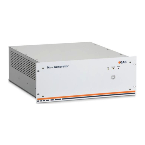
Nitrogen Generator with accessories
(example picture)
µTD with accessories

GC-IMS–User Manual
13/214
Laptop Computer (different design) including
software for control and evaluation
Luer Adapter (1 piece)
Luer Adapter Heater (1 piece)
Sampling Syringe 5ml syringe for Luer
Adapter) (100 pieces)

GC-IMS–User Manual
14/214
1.5 Liability and Guarantee
This user manual describes the safe and proper handling of the device.
All data and reference within this manual are compiled under the valid regulations,
the state-of-the-art as well as G.A.S. experiences of several years.
This user manual must be stored together with and close to the device at any time
and accessible to all persons, who operate or handle the device at any time.
This user manual must be read carefully before starting to work with the device.
G.A.S. does not assume any liability for damage and disturbances, resulting from
disregard of the instructions contained in this user manual. All claims of any kind
related to damage from a not intended use of the device will be rejected.
G.A.S. reserves the right to realize technical changes of the product due to
improvements without explicitly mentioning them.
1.6 Copyright
The manual is confidential. It is beyond doubt exclusively made and also meant for
the personnel directly dealing with the equipment. All data, texts, designs, pictures
and other representations within this manual are protected in the sense of the
copyright law and are subject to further commercial patent rights. Each abusive is
punishable by law.
Passing it on to third persons as well as duplications in any kind and form - also in
part - as well as the use and/or report of contents are not permitted without written
agreement of the manufacturer. Offences lead to payment of damages. We reserve
ourselves all rights of the practice of commercial patent rights.
1.7 Return and Disposal
For an adequate disposal, the device or/and its equipment must be returned to the
G.A.S. or to a third party authorized by the G.A.S.! For questions please contact
G.A.S.
1.8 Software Updates
If there are any software updates customers will be contacted by G.A.S. Gesellschaft
für analytische Sensorsysteme mbH as soon as the updates are available. The
updates are free of charge within the first 12 month after delivery. Users will be

GC-IMS–User Manual
15/214
provided with information about the changes and instructions for executing the
updates.
1.9 Customer Service
For questions concerning G.A.S. products a customer service is available:
G.A.S. Gesellschaft für analytische Sensorsysteme mbH
Otto-Hahn-Straße 15
44227 Dortmund
Germany
Phone: +49 (0) 231 / 97 42 - 65 50
Fax: +49 (0) 231 / 97 42 - 65 55
The telephone hotline is available from monday to friday from 9:00 to 16:00 hours. In
urgent cases or if you use fax or email please provide a telephone number for
callbacks.

GC-IMS–User Manual
16/214
2 Safety
2.1 Intended Use Only
WARNING!
Usage other than described in this manual may damage the device
and/or harm persons involved.
Do not use the device for other purposes. Damages due to misuse
are not covered by the guarantee. Such damage claims will be
rejected.
The device and its equipment are not certified for the employment in
areas with explosive gas air mixtures.
All claims or requirements of any kind against the manufacturer and/or its authorized
persons that arise due to damages from a not intended use of the device will be
rejected. All damages that arise from a not intended use are of the operator’s
responsibility.
The intended use of the equipment and its correct handling according are described
in the operating instructions of this manual. Other parts than the parts belonging to
the scope of supply, may only be used after G.A.S. approval.
2.2 Responsibility of Operator
The device may only be operated in a perfect technical condition. Before putting the
device into operation the condition of the device and its equipment must be checked.
The information and instructions provided in this manual have to be followed at any
time.
Besides the instructions provided in this manual the local rules for the prevention of
accidents, general safety regulations - valid for the area of application of the device -
as well as the valid environmental-protection regulations must be considered and
respected.
The responsible technicians and operators have to make sure a failure-free use of
the device. Responsibilities among the involved persons regarding installation,
operation, maintenance and cleaning must be made clear.

GC-IMS–User Manual
17/214
2.3 Requirements of Personnel
Only authorized and trained technical personnel may work with the instruments. The
operator must have received an instruction over existing and all possible dangers
and should be regularly instructed in safety procedures and environmental protection
and that the personnel is fully aware of the complete operating instructions and
particularly the safety notes. Personnel that might be under the influence of drugs or
alcohol are to be kept off the device at any time.
Technical personnel in this context are defined as skilled employees who are
knowledgeable due to their educational background. In case the foreseen personnel
do not have the necessary qualifications to operate the instrument, it must be trained.
Further to that non-authorized personnel should not operate the device.
The competencies for the work on and with the device must be specified and kept
undoubtedly at any time so that with respect to security issues no unclear situation
might come up.
Any changes of the equipment, which impair security of the personnel, must
immediately be reported to the operator and every person dealing with it.
2.4 Dangers
The device and its equipment is subject to an endangerment analysis. The
construction and execution of the device corresponds to the today's state-of-the-art.
The device is reliable in service when operated according to its intended use.
INFORMATION!
If the housing of the device is damaged, the device must not be used
anymore and must be returned to the G.A.S. by using the original
transportation case.
DANGER
The GC-IMS device contains a radioactive radiation Tritium source of
75 MBq which in all EURATOM countries is below the exemption limit.
However, do not open the device! Do not try to recover malfunctions
of the device! Malfunction recovery, repairs and any maintenance
work may only be performed by G.A.S. or by qualified personnel
authorized by G.A.S.

GC-IMS–User Manual
18/214
DANGER
The GC-IMS and its equipment is not certified for the employment in
areas with explosive gas air mixtures (Zone 0).
DANGER
Exercise great care in handling current-carrying parts like the power
supply cord. Do not get directly in touch with current-carrying parts.
Do not open the housing. Do not use damaged parts.
DANGER
When Nitrogen is used as drift gas and helium as carrier gas,
ignition of a helium plasma may occur due to the high voltage
present in conjunction with a radiation source. This can damage the
IMS.

GC-IMS–User Manual
19/214
3 Transport, Packing and Storage
3.1 Inspection after Transport
Check the supply immediately after delivery concerning its completeness and/or
transport damages. If you detect externally visible transport damage, do not receive
the supply, or only under reservation. State the extent of the damage on the provided
delivery note and/or the transportation documents of the feeder. Generate a
complaint. Lodge a complaint of covered defect immediately after recognizing, as
claims due to transport damages can only be made valid within the complaint periods
(usually 7 days).
3.2 Packing
If no return agreement regarding the packing was agreed upon dispose the
packaging material always in an environmentally friendly way and according to valid
local regulations. If necessary, ask a recycling company.
INFORMATION!
It is recommended to keep the transport box for a safety return
transport.
3.3 Storage and Transport
Store the device only under the following conditions:
•When not in use store the equipment in the supplied casing
•Prevent unauthorized access
•Do not store outside
•Protect the equipment from moisture and dust
•Put protective caps on all gas sockets
•Avoid mechanical vibrations
•Do not expose the equipment to aggressive substances
•Protect the equipment from direct sun light

GC-IMS–User Manual
20/214
•Storage temperature: 5 to 40 °C
•Relative Air Humidity: 0- 90%Rh, non condensing
•Instrument’s position: Horizontal
The equipment should be moved only within the provided carrying case. By this
means, transport damages can be avoided. The above-mentioned values are
considered for an instrument transported in its original new packing.
WARNING!
Protective caps should be put on gas sockets in case the device is
stored or transported.
4 Cleaning and Maintenance
Natural aging and the wear of certain components of the equipment require a regular
cleaning and maintenance.
4.1 Cleaning
Clean the device only with a dry or easily damp cloth.
WARNING!
Do not use cleaning agents, which contain solvents, acids or
bases.
4.2 Maintenance
INFORMATION!
Maintenance of the device should only be carried out at G.A.S. or
through specially trained and by G.A.S. authorized personnel.
The recommended maintenance interval is 12 months.
Table of contents
Other GAS Portable Generator manuals
