Gasboy CFN ISLANDER II User manual

CFN ISLANDER II
WITH KEY OPTION
CONVERSION MANUAL
C36053
REV. 04/15/03
Copyright 2003 by Gasboy International LLC All rights reserved.
The information in this document is confidential and proprietary. No further disclosure shall be made without
permission from Gasboy International LLC. Gasboy International LLC believes that the information in this document
is accurate and reliable. However, we assume no responsibility for its use, nor for any infringements of patents or
other rights of third parties resulting from its use. We reserve the right to make changes at any time without notice.
GASBOY INTERNATIONAL LLC LANSDALE, PA


04/15/03 1
ISLANDER II WITH KEY OPTION CONVERSION
USING THIS MANUAL
These instructions are provided to assist the system operator in the conversion of a GASBOY
CFN Islander II (mag or optical) system, or satellite islander (mag or optical) reader to a key
version. The instructions contain:
• an illustrated parts breakdown
• steps for converting the system from mag or optical to key
• system checks and diagnostics to verify proper operation

Islander II With Key Option Conversion
2 04/15/03
CONTENTS OF THE CONVERSION KIT

Islander to FleetKey Conversion
04/15/03 3
CONTENTS OF THE CONVERSION KIT (C05898)
Item Part No. Description
1 C04371 Trim edge material (2”)
2 C36030 PCB I/F mounting brkt.
3 C04037 2 Screws, #8-32 x 3/8
4 C05159 Key I/F PCB assembly
5 C04125 2 F/Fstandoffs, #8-32 x 1
6 C01166 3 Split lock washers, #6
7 C04039 3 Screws, #6-32 x ½
8 C35287 Key adapter bracket-Dual
C35298 Key adapter bracket-Single
9 C05881 2 Ribbon cable assy, 26-position
10 068842 4 Star lock washers, #8
11 C06043 Ribbon cable assy, 26-position
12 C02848 2 Key receptacle devices
13 C08126 2 Tie wraps, 8” long
14 C05880 DC power cable assy, I/F PCB
15 C09499 Key insertion instructions decal
16 C06426 Prog’d. EPROM chip (V6.0 or >)
17 C01625 Key, serial memory - black
18 C01624 Key, serial memory - gray
19 C01623 Key, serial memory - green
20 C34843 Cover assy.
21 C36053 Instructions (This document)

Islander II With Key Option Conversion
4 04/15/03
CONVERSION INSTRUCTIONS
Use the following instructions to convert your system. The first two subsections detail removal of
your old Mag or Optical card reader unit. The next section details installation of the new key
unit(s). Assembly drawings appear at the end of these instructions for your reference.
IMPORTANT
Before proceeding with conversion please note that the Site Controller operating system
software that you are running on must be V2.2B or above; if not, an updated version must
be obtained before the conversion can continue.
REMOVE MAG READER
1. Unlock and open the rear door on the head of the Islander.
2. Turn off the AC power switch located on the bottom right.
3. Remove the hood of the unit.
IMPORTANT
Once again, before going any further with the conversion, check that the CPU PCB,
mounted to the inside of the right vertical panel when facing front of unit, is C05857 ICR2
CPU PCB assembly. If not, obtain this board assembly before proceeding.
4. Working inside the head of the unit, remove the four screws that secure the external cover
assembly (shields the mag card reader) to the face of unit. Save these screws; they will be
reinstalled later with the new cover assembly. Discard old cover assembly.
5. Locate the P1 and P1A connector(s) in
the bottom left corner of the ICR2 CPU
PCB and disconnect the cable attached
at one of these positions.
Still inside the head, remove the two
screws that secure the mag card reader
to the face of the unit; remove mag card
reader with cable and rubber gasket
from the unit.
6. Proceed with the Installation of Key
System instructions.
REMOVE OPTICAL READER
1. Follow Steps 1 through 3 under Remove Mag Reader including IMPORTANT statement.
2. Locate the P5 connector on the right side of the ICR2 CPU PCB and disconnect the attached
ribbon cable.
3. Disconnect the +5VDC power cable (black and orange) that supplies the optical reader.

Islander to FleetKey Conversion
04/15/03 5
4. Still inside the head, remove the two screws which secure the optical reader bracket to the
inside face of the unit (the same two screws help secure the bottom of the external card
reader cover assembly). Remove the entire optical reader assembly from the head.
5. Still inside the head, remove the remaining two screws which secure the external reader cover
assembly. NOTE: Be careful when removing this external cover assembly from the face of
the unit because the optical reader adapter plate will come off with it. The four screws and the
reader cover assembly will be reused later; however, the Optical reader adapter plate will not.
6. Proceed with the Installation of Key System instructions.

Islander II With Key Option Conversion
6 04/15/03
INSTALLATION OF KEY SYSTEM
1. From the outside of the unit, insert the two threaded studs of the conversion kit single or dual
key adapter bracket into the two mounting holes in the face of the unit where the mag or
optical card reader was mounted. The four slotted holes in the adapter bracket must line up
with the four holes in the face of the unit. If not, rotate the adapter bracket.
2. With the proper orientation of the key adapter bracket now known, install the conversion kit
key receptacle(s) by snapping them into the large square key adapter bracket holes. Before
snapping in, be sure that the PCB connector of each key receptacle is facing up.
3. Install the conversion kit 10-position ribbon cable(s) by inserting one end into the keyed
opening in the top of each key receptacle and letting the other end hang free for now. Secure
the ribbon cable(s) to the key receptacle(s) with the conversion kit tie wrap(s).
4. Working inside the head, with the key adapter bracket assembly in position against the front
face, slip a conversion kit star lock washer over each stud of the key adapter bracket and then
secure the two conversion kit F/F standoffs to these studs.
5. Install the new cover assembly using the four screws previously removed. Make sure cover
hinges upward before tightening screws.
6. From the conversion kit, press the trim edge material (two 1” long pieces) onto the bottom two
edges of the PCB I/F mounting bracket.
7. Align the two slotted holes of the PCB I/F mounting bracket with the two standoffs just
installed and using conversion kit star lock washers and # 8 screws, secure PCB I/F bracket to
inside face of unit. NOTE: The components of the I/F PCB assembly will be facing the rear of
unit.
8. Using the # 6 screws and split lock washers from the conversion kit, secure the Key I/F PCB
assembly to the I/F bracket. NOTE: The components of the I/F PCB assembly will be facing
the rear of unit.
9. Route the unconnected 10-position ribbon cable(s), from Step 3 above, over the top of the I/F
bracket and insert into the keyed connectors on the I/F PCB assembly.
10. Install the conversion kit 26-position ribbon cable by inserting one end into the keyed P1
connector of the Key I/F PCB and the other end into the keyed P5 connector (aux/optical
reader) of the ICR2 CPU PCB assembly.
11. Install the conversion kit DC power cable by inserting the end with the smaller connector into
the P2 connector of the Key I/F PCB. The cable end with the larger connector plugs into the
unused connector that is snapped into the inside left vertical panel (near the bottom when
facing front of unit).
12. If the EPROM chip (U13 in your C05857 ICR2 CPU PCB assembly is version 6.0 or higher,
skip to Step 13; otherwise, remove this chip from the U13 socket and install the conversion kit
programmed EPROM, which contains the software revision for the Key system.
13. The above ICR2 CPU PCB assembly also contains a S2 bank of 10 DIP switches, some of
which are set according to what type of reader is being used. For what is now a Key system
the required settings are: S2, position 4 = closed and S2, position 6 = closed. For a complete
description of all switch settings see Islander II Start-up Manual, C01665.
14. On the front face of the unit in the lower righthand corner is either a mag or an optical reader
pictured. Clean off any dirt and dry this area before using the self-adhesive Key insertion
decal supplied in the conversion kit. Peel backing off decal and apply it over this existing
diagram.
15. Proceed with Power On and Test instructions.

Islander to FleetKey Conversion
04/15/03 7
SIDE VIEW
PARTIAL INTERIOR
FRONT VIEW
PARTIAL

Islander II With Key Option Conversion
8 04/15/03
POWER ON AND TEST
1. When you have finished installing the conversion kit, turn on the power for the Islander unit.
If the unit does not power up, turn the power off and verify all cables are on and in the correct
locations. Turn on the power for the Islander unit again.
If the unit still will not power up, contact Gasboy Technical Service at (800)444-5529.
2. Using a calibrated multimeter, measure the +5 VDC between TPI (+) and TP2 (-). The voltage
should be +5.05 ±.1 VDC. Adjust if necessary. Measure the + 12 VDC between the red (+)
and black (-) wires on the DC OUTPUT connector of the power supply. The voltage should be
between +11.0 VDC and +14.0 VDC.
3. Move the toggle switch S3 to the self-test or down position.
4. Press the Start Over button and Self Test Mode will appear on the display.
5. Press “.” on the keypad and the display will show Insert Key. Insert a programmed test key
and turn it to the left. The display will show CRC1 OK, CRC2 OK followed by the key data.
Continue to press the Start Over button until all key data is shown and you return to the Self
Test Mode prompt. Remove your test key from the receptacle. NOTE: If you have dual key
receptacles, repeat self test to test both receptacles.
6. Remove the test key and move the toggle switch S3 to the on-line or up position and press the
S1 reset button.

Islander to FleetKey Conversion
04/15/03 9
CONFIGURING THE SITE CONTROLLER
A Key option is available for Islander II sites. The following configuration adjustments must be
made to the Site Controller configuration for this option.
SYSTEM PARAMETERS (SYS PAR)
The following setting must be used to configure the Site Controller to accept keys.
• Page 2: Club card format - field widths
Digits in limitation code = 1
Digits in authorization code = 1
Digits in price level = 1
Digits in restriction code = 1
Digits in expiration date = 4
• Page 3: Club card format - offsets
Limitation code offset = 0
Authorization code offset = 1
Price level offset = 2
Restriction code offset = 3
• Reader verification - page 4
The key option on the CFN allows the PIN number to be stored on the key. If you are using
this option, when the user enters the PIN at the reader, it is verified against the PIN stored on
the key. These PIN numbers do not use the standard CFN algorithm and are verified at the
reader. In order to use this option, you must set the following reader verification parameters:
Require PIN (reader) = none
Check PIN (reader) = none
NOTE: The check digit on the key must be set to require PIN in order to verify the key
PIN number. Refer to the KE200 Key Encoder/Maintenance Terminal Operation
Manual, C08380 for more information.
If you are using key and card combinations (verifying the PIN for the card), code keys (using
the Lookup tables), or verifying the PIN based on an Account field number and not the
number stored on the key, you must set the following reader verification parameters:
Check PIN (reader) = club
NOTE: The check digit on the key must be set to NOT require PIN. Refer to the KE200
Key Encoder/Maintenance Terminal Operation Manual, C08380 for more
information. If you are verifying the PIN based on an Account field number from
the key, set the following parameter:
Require PIN (reader) = club

Islander II With Key Option Conversion
10 04/15/03
• Miles-per-gallon package - page 13
The Key option on the CFN allows the odometer to be stored on the key for reasonableness
check. If you are using this option, when the user enters the odometer, it is verified at the
reader against the odometer stored on the key. If you are using this option, you must set the
following system parameters
MPG package used for club cards = no
If you are using the MPG package feature of the CFN system, set the following system
parameters:
MPG package used for club cards = yes
Maximum miles between fuelings = (4 digit #, Max. 9999)
Club odometer tries allowed = 0
ISLAND CARD READER (READER)
The Island Card Reader (ICR) reader program (MENU 1) must be set-up as follows:
• Step 3 - PIN
Enter PIN message must be preceded by a space, must be in all capital letters and
must say ENTER YOUR PIN.
Number of digits = Must be at least 4
Optional = yes
• Step 7 - Odometer
Use default Enter Odometer message
Number of digits = 6
Optional = yes
• Step 11 - Remove Card
This step must be used with systems that have the key option. The message can be
changed to read: Remove Key or Remove Card/Key.
An example is shown below:
8] 7( (-740%= ;,-0))28)6-2+ 348-327
-27)68'%6(
)28)6=3964-2 =3964-2 348-32%0
)28)63(31)8)6 3(31)8)6 348-32%0
40)%7);%-8
7)0)'84914291 )64914
6)13:)/)=7
)+-2*9)0-2+
)2(

Islander to FleetKey Conversion
04/15/03 11
PIN KEY
The Key option requires a 4-digit PIN key to be loaded at the Site Controller. Use the command
LOad KEY to enter this PIN. The LOad KEY command requires 18 digits to be entered at the
prompt. Key systems will use only the last 4 digits. Place 0’s (zeros) in the first 14 digits with the
final 4 digits the required PIN key. Use the example as a guide.
If PINs are being calculated from a mag card in a card/key combination, the PIN key is still loaded
in SYS_PAR.
Example: PIN is 1234. (In actual use, data is masked; it is shown here for example only.)
03/)
↵
/I]#
↵
Upon completion of this Configuration section, your converted Islander with Key option system
should be working and fully operational. If you have any questions, please call Gasboy Technical
Services at 1-800-444-5529.
Table of contents
Other Gasboy Controllers manuals
Popular Controllers manuals by other brands

Aerotech
Aerotech ABL9000 Series user manual
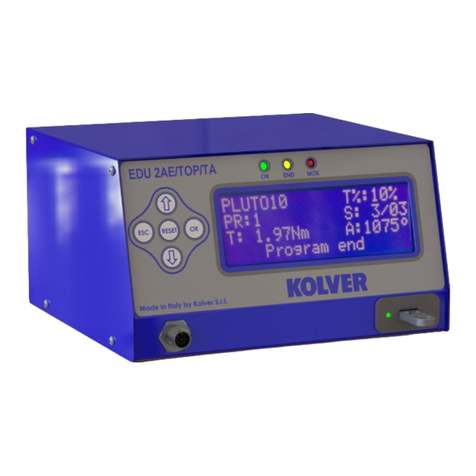
Kolver
Kolver EDU 2AE/TOP/TA manual

Denali
Denali GEN II CANsmart DNL.WHS.24600 instruction manual

Rockwell Automation
Rockwell Automation PowerFlex 700S installation manual

Merlin
Merlin HSGC Installation & operation manual

Liscarroll Engineering
Liscarroll Engineering LE-300 Installation and operating instructions
