manuals.online logo
Brands
  1. Home
  2. •
  3. Brands
  4. •
  5. ELREHA
  6. •
  7. Controllers
  8. •
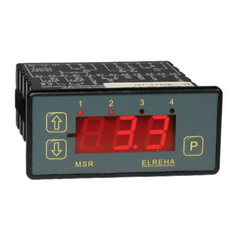
  9. ELREHA TARN 1600 User manual

ELREHA TARN 1600 User manual

zz
zz
zController for Milk Cooling and Milk Storage
Applications
zz
zz
zReplaces single Thermostats,
Digital Displays and Stirrer Timers
zz
zz
zStirrer Control, adjustable
zz
zz
zDigital Temperature Display for Actual Values
and Setpoints, °C or °F
zz
zz
zMin/Max Memory
zz
zz
zOver-/Undertemperature Alarm,
Alarm Relay, Emergency Mode
zz
zz
zFoil Keypad, Housing for Panel-/Door Mounting
Operating Elements
Parameters
All selectable parameters hold a parameter number (e.g. P02), you
will find a listing on the next page.
Calling up and editing
Press key "P" ................................... parameter number appears
Use
"×/Ø"
............................................ select desired parameter
Press "P" again .................................... parameter value appears
Use keys
"×/Ø"
....................................... adjust parameter value
Press "P" again ................ value is stored, back to parameter no.
Unlock Keys
To prevent un-authorized persons from editing parameter values,
there is a locking function which allows only the most important
parameters to be changed at any time. The access code can
entered as follows:
Press key "P" ................................... parameter number appears
Use
"×/Ø"
.......................................select code parameter (P15)
Press "P" again .................................... parameter value appears
Use key
"×"
................................................. set code No. to "88"
Press "P" again ................ value is stored, back to parameter no.
If no key is hit for about four minutes, the editing function is locked
again.
Auto scrolling
Hold
"×/Ø"
-keys to scroll values automatically.
Manual Stirrer Control
While the Actual Value is visible:
Hold key "P" >3 seconds ............... Stirrer starts, LED flashes.
Stirrer stops automatically when timer P06 is run down
or
Hold key "P" >3 seconds ............... Stirrer stops, LED off.
Reading the Minimum/Maximum Value
While the Actual Value is visible, the highest and the lowest
occured temperature value can be read:
• Hold key "×" until "H1" appears, then release key.
For the next 3 seconds the display shows the highest value.
• Hold key "Ø" until "L0" appears, then release key.
For the next 3 seconds the display shows the lowest value.
Erase the Minimum/Maximum Memory
Read any Min/Max Value, then press "P"-key immediately until
"del " appears. Now the memory is erased.
Reset Temperature Alarm
Press any key.
Stirrer
Blinking: Manually ON
Continuous: Automatically ON
Decimal Point
Decrease
Values
TAR
Cooling ON
Increase
Values
ELREHA
P
Alarm
Blinking: Reset,
but still available
Programming
key
Please note Safety Information
on Page 3 !
No. 5311231-02/00E
Softw.Vers. al05xxxx
Milk Cooling Controller TARN 1600
ELEKTRONISCHE REGELUNGEN GMBH
D-68766 Hockenheim, Germany
Schwetzinger Str. 103
phone 0 62 05 / 2009-0
fax 0 62 05 / 2009-39
email [email protected]
internet www.elreha.de
Page 2 Technical Manual Milk Cooling Controller TARN 1600
Failure Display / Failure Behaviour
Display shows "SEH" and flashes (Sen-
sor Error High), Beeper sounds:
Temperaturesensor input isopen,wrong
sensor,sensordamagedor cable broken.
Display shows "SEL" and flashes (Sen-
sor Error Low), Beeper sounds:
Temperature sensor cable has short
circuit, wrong sensor or short circuit of
sensor itself.
Display shows "HA" and flashes (High
Alarm), Beeper sounds:
Upper alarm threshold (P12) increased.
Display shows "LA" and flashes (Low
Alarm), Beeper sounds:
Loweralarm threshold(P13) decreased.
Emergency Mode
If the control sensor fails, the controller starts an emergency mode.
Then the refrigeration relay and the stirrer switch ON in a percentage
rate of a total period of 30 minutes, preset by P04.
E.g.: selecting 40% means 12 minutes on, 18 minutes off.
Technical Data
Supply Voltage ................... TARN 1600 ........... 230 AC / 50 Hz
TARN 21600 ......... 115 AC / 60 Hz
Power Consumption................................................ max. 4,4 VA
Relay Contact Rating ......... K1, 10A res., 80A/20 msec, 250V AC
K2, K3 ................................ 5A res.
Operating-/Storage Temperature ........ -10...+50°C / -30...+70°C
Air Humidity ................................max. 80% r.F., not condensing
Temperature Sensors ........ TF 101, TF 201 or TF 501 (Pt1000)
Display .................................. LED, red, character height 13mm
Resolution .............................................................. 0,1°C / 0,2°F
Accuracy .................................................................... typ. +/- 1K
Control-/Display Range
with TF 101 ........................................... -5...+30°C / 23...86°F
with TF 201 .................................... -55...+105°C / -67...221°F
with TF 501 ................................ -110...+120°C / -166...248°F
Data Storage ................................................................ unlimited
Relay Indicator ................................................... LED 3 mm, red
Electrical Connection .......... pluggable screw terminals 2,5mm²
Protection ........................................................... IP 54 from front
Param. Disp. Code Description Range Default Your value
No. onl.
P01 X -- Actual temperature -30..100°C
P02 -- Setpoint 0..30,0°C 4
P03 88 Hysteresis 0,3..10K 1
P04 88 Emergency mode , x% ON-time of 30 minutes 0..100% 0
P05 88 Stirrer interval 1..255min 60
P06 88 Stirrer runtime 0..255sec 10
P07 88 Temperature correction -10,0..10,0K 0
P08 88 Sensor type 1=TF101, 2=PT1000, 3=TF201 1
P09 88 Display Resolution 1=0,1K 2=1K 2
P10 88 Display Mode 1=°C 2=°F 1
P11 88 Alarm delay 0 .. 255min 60
P12 88 Upper Temperature Alarm Threshold 0..50,0°C 50
P13 88 Lower Temperature Alarm Threshold 0..P11 0
P14 88 Stirrer Delay after Power-up 0..30min 0
P15 -- Code 0..100 - -
ON
30 minutes
Emergency Mode
in %
Cooling OFF
Cooling ON
OFF
Technical Manual Milk Cooling Controller TARN 1600 Page 3
Functional Description
Applications
The TARN 1600 is a combined controller, which
controls temperature by switching a solenoid
valve or a compressor and a stirrer, which is
necessary for milk cooling/storage applications.
Temperature Display
The measured temperature value (P01) can be
read on the display with a resolution of 1K or 0,1K
(selectable by P09). The display is also able to
show °C or °F (P10).
Different temperature sensor types can be used:
TF 101, TF 201 and TF 501 (Pt1000), selectable
by P08. Please note that they have different
temperature ranges.
Min/Max (Peak Value) Memory
The controller always stores the highest and the
lowest measured temperature value, which can
be read by the
"×"
and
"Ø"
keys (see page 1).
Sensor Correction
In case of display deviation (e.g. sensor position,
deviation by cable lenght, etc.), the display can be
corrected by parameter P07.
Temperature Controller
The temperature controller works as follows:
• Cooling ON
(Cooling relay activared = Compressor ON):
Actual Value > (Setpoint P02+Hysteresis P03)
• Cooling OFF
(Coolingrelayde-activared=CompressorOFF):
Actual Value < Setpoint P02
An adjustable switching hysteresis prevents from
short switching cycles (P03).
Dependingonthemountingpositionofthesensor,
sensor type and its mass, control deviations may
occur which are wider than the set hysteresis.
Stirrer Control
Afterpower-upofthe controller, the stirrer switches
ON delayed by P14, if no cooling is necessary.
While normal operation, the stirrer relay is always
activated with the cooling relay. After the cooling
relay has been switched OFF, the stirrer trails for
the time set by P06. After that, the stirrer operates
with the ON/OFF-times set by P05/P06.
The stirrer can also be started and stopped
manually (see page 1).
Temperature Alarm
A temperature alarm is forwarded by:
• a LED on the front
• by an integrated beeper
• by an alarm relay
Whenthemeasuredtemperature leaves the range
set by P12 / P13, a delay timer (P11)starts. After
this timer has been run down, a temperature
alarm will be generated.
By pressing any key, the alarm is reset for about
10minutes.Whilethistime, the alarm LED flashes.
After the end of this period, the alarm is repeated.
If the temperature comes back to the normal
range, alarm relay, beeper and LED are reset
automatically.
war
m
activated
de-activated
cold
setpoint
hysteresis
CONNECTION INFORMATION & SAFETY INSTRUCTIONS
Please read before Start-up
The guarantee will lapse in case of damage caused by failure to
comply with these operating instructions! We shall not be liable for
any consequent loss! We do not accept liability for personal injury
or damage to property caused by inadequate handling or non-
observance of the safety instructions! The guarantee will lapse in
such cases. Cleaning: The use of a dry, lint-free cloth is sufficient to
clean the product.
If you notice any damage, the product may not be connected to
mains voltage! Danger of Life!
A riskless operation is impossible if
• The device has visible damages
• The device doesn't work
• After a long-time storage under unfavorable conditions
• After inadequate shipping conditions
• Limit of Application: This product is not designed nor
manufactured for use in equipment or systems that are
intended to be used under such circumstances that may
affect human life. For applications requiring extremely high
reliability, please contact the manufacturer first.
The product may only be used for the described
applications.
• Electrical installation and putting into service must be
done from authorized personnel.
• Please note the local safety instructions and standards !
• Before installation: Check the limits of the controller and
your application. Before starting up we recommend you to
read the manual for use, since only by doing so you can
avoid damage or malfunction and you will benefit all the
advantages offered by this product.
•During installation and wiring never work when the
electricity is not cut-off !
•Never operate unit without housing.
• Connect the ‘PE’ terminal carefully to ground because
otherwise the operation of the internal noise filter will be
disabled.
• Mounting the controller close to power relays is
unfavourable in case of the electro-magnetic interference.
• Before applying voltage to the controller:
Make sure that all wiring has been made in accordance
with the wiring diagram in this manual.
Check, if the supply voltage corresponds to the value
printed on the type label.
• Respect the environmental limits for temperature and
humidity. Outside these limits malfunctions may occur.
• Observe the maximum admitted current rate for the
relays (see technical data). Compare with the peak start-
up current of the controlled devices (fan, compressor,etc.)
• Use shielded cable for sensor elongation only. Don’t install
them in parallel with high-current cables to prevent inductive
interference. A wire gauge of min. 0,5mm² is sufficient.
• Shielding must be connected to PE at the end near the
controller
• All used temperature sensors must be identical. Never
different sensor types mixed. This will not work.
• TF-type sensors are not designed for being immersed in
fluids for a long period of time (not pressure-proof). In such
a case, always use dip-fittings.
Page 4 Technical Manual Milk Cooling Controller TARN 1600
Dimensions and Wiring
Front frame
can be removed
Snap in fixing frame
from rear side.
P
TAR ELREHA
76 (3.0)
35(1.38)
Rückansicht mit Befestigungsrahmen
75 (2.95)
rear view with mounting frame
37(1.46)
70 (2.76)
28(1.1)
70(2.76)
11
810
9
67
15
4
23
ELREHA
MilkCoolingController
Milchkühlregler
230VAC
56 (2.2) 3 (.12)
Für das beschriebene Erzeugnis wird hiermit bestätigt, daß bei bestimmungsgemäßem Gebrauch die Anforderungen eingehalten
werden, die in der Richtlinie des Rates zur Angleichung der Rechtsvorschriften der Mitgliedsstaaten über die elektromagnetische
Verträglichkeit (89/336/EWG) und der Niederspannungsrichtlinie (73/23/EWG) sowie der Änderungsrichtlinien (93/68/EWG) festgelegt sind.
Diese Erklärung gilt für alle Exemplare, auf die sich die vorliegende Bedienungsanleitung (die selbst Bestandteil dieser Erklärung ist) bezieht.
We state the following: When operated in accordance with the technical manual, the criteria have been met that are outlined in the guidelines of the
council for alignment of statutory orders of the member states on electro-magnetic consistency (89/336/EWG) and the Low Voltage Directive (73/23/
EWG) as amended by (93/68/EWG). This declaration is valid for those products covered by the technical manual which itself is part of the declaration.
Zur Beurteilung des Erzeugnisses hinsichtlich elektromagnetischer Verträglichkeit und der Niederspannungsrichtlinie wurden jeweils die aktuellen
Ausgaben der betreffenden Grund- und Fachgrundnormen herangezogen.
To meet the requirements, the currently valid versions of the relevant standards have been used.
Diese Erklärung wird verantwortlich vom Hersteller/Importeur abgegeben durch:
This statement is made from the manufacturer / importer by:
ELREHA Elektronische Regelungen GmbH Werner Roemer, Technischer Leiter, Technical Director
D-68766 Hockenheim
(Name / Anschrift / name / adress)Hockenheim.............21.10.2004.......................................................
Ort/city Datum/date Unterschrift/sign
EG-Konformitätserklärung EG-Statement of Conformity
10
9
8
6
7
3
5
4
1
2
panel
supplied
gasket
70 (2.76)
cut-out
28 (1.1)
mounting
Created: 30.3.07, tkd/jr Checked: Released:
This documentation was compiled with utmost care, however, we cannot guarantee for its correctnesss in every respect.
All rights reserved. Subject to change without notice.

Other ELREHA Controllers manuals

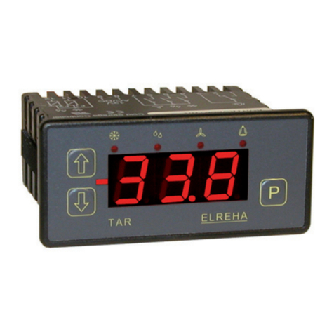
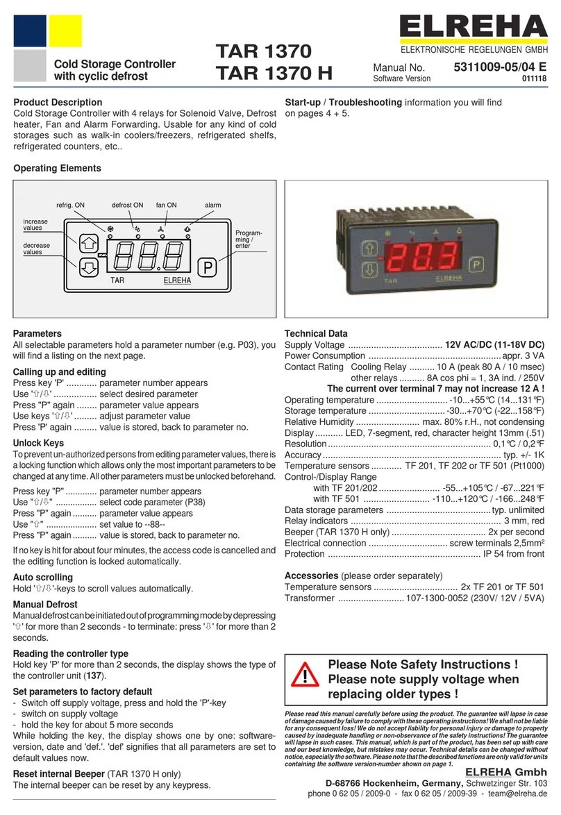
ELREHA TAR 1370 User manual

ELREHA

ELREHA TAR 1370 User manual

ELREHA TAR 1810-2 User manual

ELREHA

ELREHA TAR 1810-2 User manual

ELREHA EVP 3260 User manual

ELREHA

ELREHA EVP 3260 User manual

ELREHA TAR 1260 User manual

ELREHA

ELREHA TAR 1260 User manual

ELREHA TKP 3130/1 User manual

ELREHA

ELREHA TKP 3130/1 User manual

ELREHA TAR 1170 User manual

ELREHA

ELREHA TAR 1170 User manual

ELREHA EVP 3150-1 User manual

ELREHA

ELREHA EVP 3150-1 User manual

ELREHA MSR 100 Series User manual

ELREHA

ELREHA MSR 100 Series User manual

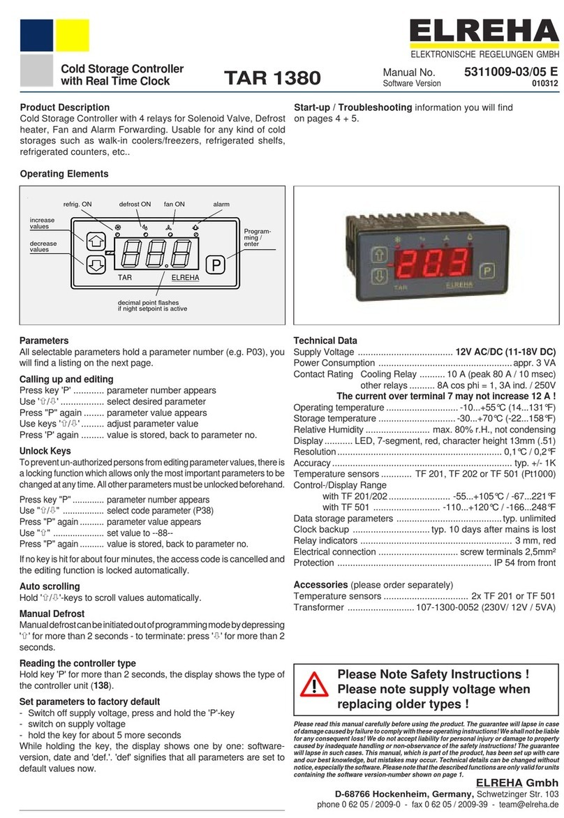
ELREHA TAR 1380 User manual

ELREHA

ELREHA TAR 1380 User manual

ELREHA EVP 3167 How to use

ELREHA

ELREHA EVP 3167 How to use

ELREHA MSR eco 3140 User manual

ELREHA

ELREHA MSR eco 3140 User manual

ELREHA TAR 1370-2 User manual

ELREHA

ELREHA TAR 1370-2 User manual

Popular Controllers manuals by other brands

Light O Rama CTB08 Installing

Light O Rama

Light O Rama CTB08 Installing

Santerno SINUS PENTA Series Guide

Santerno

Santerno SINUS PENTA Series Guide

ComfortClick Jigsaw manual

ComfortClick

ComfortClick Jigsaw manual

Fisher 912 Series instruction manual

Fisher

Fisher 912 Series instruction manual

Bosch Rexroth IndraControl VPB 40.3 operating instructions

Bosch

Bosch Rexroth IndraControl VPB 40.3 operating instructions

Elko LIC-2 manual

Elko

Elko LIC-2 manual

B&C CL 7685 Operator's manual

B&C

B&C CL 7685 Operator's manual

KE2 Therm Solutions Evaporator Efficiency installation instructions

KE2 Therm Solutions

KE2 Therm Solutions Evaporator Efficiency installation instructions

SM Pro Active-1 operating manual

SM Pro

SM Pro Active-1 operating manual

Gardena 1892 Operator's manual

Gardena

Gardena 1892 Operator's manual

Zennio MAXinBOX 16 Technical documentation

Zennio

Zennio MAXinBOX 16 Technical documentation

Keysight Technologies N1002A quick start guide

Keysight Technologies

Keysight Technologies N1002A quick start guide

TechWind SDK-500 user manual

TechWind

TechWind SDK-500 user manual

Rockwell Automation Allen-Bradley Logix5000 Programming manual

Rockwell Automation

Rockwell Automation Allen-Bradley Logix5000 Programming manual

CLA-VAL CRL-60 Installation, operation & maintenance manual

CLA-VAL

CLA-VAL CRL-60 Installation, operation & maintenance manual

X10 MC460 owner's manual

X10

X10 MC460 owner's manual

Siemens RWD44U Installation and commissioning guide

Siemens

Siemens RWD44U Installation and commissioning guide

SMC Networks EX230-SDN1 Installation and maintenance manual

SMC Networks

SMC Networks EX230-SDN1 Installation and maintenance manual

manuals.online logo
manuals.online logoBrands
  • About & Mission
  • Contact us
  • Privacy Policy
  • Terms and Conditions

Copyright 2025 Manuals.Online. All Rights Reserved.