Gastrofrit ELM Series User manual
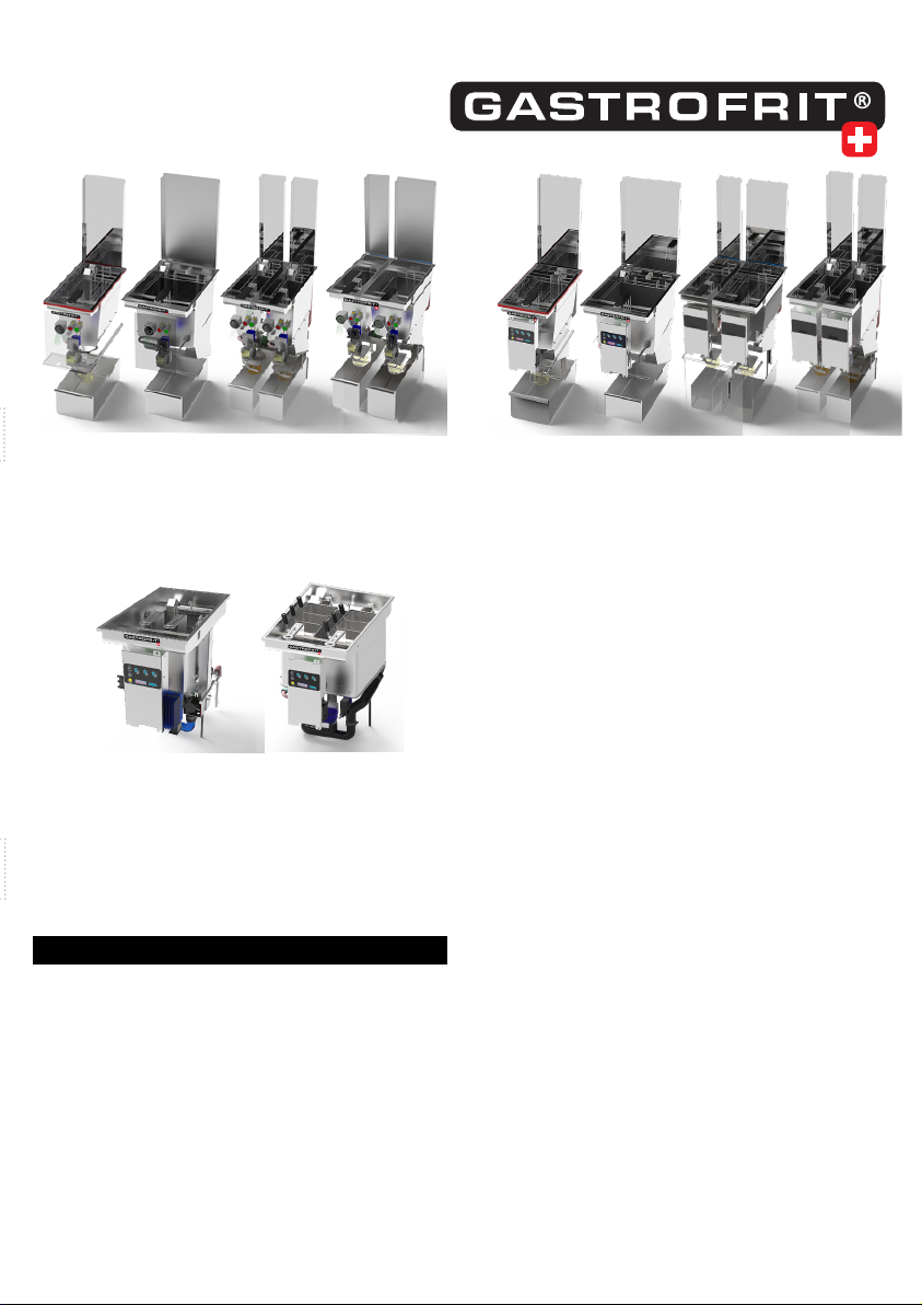
ELM-Serie / BUILT IN
TW-Serie / BUILT IN
F-Serie / BUILT IN
Operating instructions BUILT IN
FRYERS / PASTACOOKERS
Built-in electronic or electro-mechanical controls
English
Version 8.7
Thank you for choosing a Gastrofrit® product. Your
product was entirely made in Switzerland. Your pro-
duct has been subjected to a long-term test. Please
note that the performance uctuations, safeguards
and frequency ranges 50 Hertz or 60 Hertz dier in
individual countries. Before commissioning, check
the exact requirements for carefree operation of the
device.
Installation, connection and commissioning of the
control may only be carried out by persons trained by
Gastrofrit.

2www.gastrofrit.ch © Switzerland Gastrofrit AG
contents
3 Modelle und Varianten
3 Power connection / technology
3 Electricity
3 Installation of the heating basin (normal case)
3 Installation of heating basin (additional parts)
3 Assembly instructions lift motor
6 Pastacooker error catalog
7 Fault catalog deep fryers
8 Installation description of the tting box with pan
8 Fittingbox
8 Installation situation / components
9 Installation of display box
10 Mounting the bracket on the built-in stove
13 Customer service, maintenance
14 Built in drawings:

3www.gastrofrit.ch © Switzerland Gastrofrit AG
Models and variants
ELM-300 built in Item No. 101135
ELM-400 built in Item No. 101145
ELM2-400built in Item No. 101146
ELM2-500 built in Item No. 101251
F-300 built in Item No. 100130
F-400 built in Item No. 101145
F2-400 built in Item No. 102240
F2-500 built in Item No. 100251
TW-350 built in Item No. 110135
TW-400 built in Item No. 110140
Power connection / technology
Please note that the power uctuations, safeguards
and frequency ranges 50 Hertz or 60 Hertz dier in
individual countries. Before commissioning, check
the exact requirements for carefree operation of the
device.
The electricity connection may only be provided by
trained qualied personnel can be connected. Accor-
ding to the requirements stipulated in the country.
• After switching on the main switch, the device
starts and lights up in the ON / OFF LED.
• The 3x400V (3L + N + PE) power connection is
made with a standard-compliant CE plug.
Electricity
Danger: Use silicone braids for the main connection of
the devices. To guarantee trouble-free operation:
• The specications regarding cable cross-section
and fuse protection must be strictly observed.
No other devices or power consumers may be
connected to the fuse protection of the sup-
ply line. The devices were tested for their EMC
compatibility. The test reports can be viewed at
Gastroifrit.
• You need to make sure that no cables or conduits
are pinched.
Design of the area around the collection container:
The base for the collecting container should consist
of low-wear, easy-to-clean material. It is important to
ensure that the container can be removed quickly for
easy cleaning. The container should also be guided to
the side and have a dened end position.
1. Protection against accidental contact must be pro-
vided during installation.
2. The devices must not be built into ammable
material.
3. If the device is installed next to a large heat
source, sucient ventilation of the control box
must be ensured. (maximum temperature of the
control box 70 ° C)
4. Wird das Gerät neben einer großen Hitzequelle
eingebaut, ist auf eine genügende Lüftung des
Steuerkastens zu achten. (maximale Temperatur
des Steuerkastens 70°C)
Installation of the heating basin (normal case)
Inlay and silicone seal
The heating basin is placed in the corresponding ope-
ning, the joint must be sealed with silicone. The holes
provided for frame assembly can be closed with blind
rivets or screws. The silicone joint must be checked re-
gularly for leaks in order to avoid the ingress of liquids
in the long term.
Installation of heating basin (additional parts)
With frame parts or upstand kitchen cover The
heating basin can also be attached to the table with
frame parts. The frame parts should be around 20mm
shorter than the outside dimensions of the pool. When
installing in a metal cover, this can also be folded up
analogously to the frame part. The frame parts are
not part of the Gastrofrit delivery. For the installation
of the frame parts, the opening must be 2mm larger.
The joint still has to be sealed with silicone. The frame
parts are bent from 1.5mm stainless sheet metal and
screwed to the table and basin.
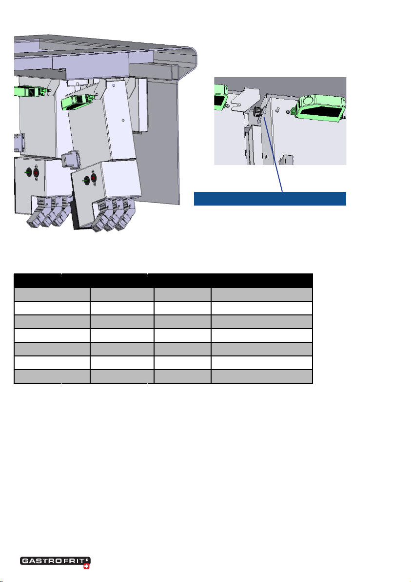
Assembly instructions lift motor
Please make sure that you have connected the power
plug correctly if it was not installed by Gastrofrit AG.
The earth (color: yellow / green, symbol 0) and the
neutral wire (color blue, symbol N) are marked in the
connector housing, connect the phases so that the
brown wire is in the middle of the two black wires.
Electrical connection of the lifting motor
The connection cable contains the following 4
strands:
• yellow/green ground wire
• blue neutral conductor
• brown Phase lift motor up
• black Phase lift motor down
When you are standing in front of the device and have
tilted the cover towards you, you can connect the
strands as follows:
Please connect the earth to the metallic (gold-colored)
earth connection. The neutral conductor to the blue
clamp, the brown phase to the left gray clamp, the

4www.gastrofrit.ch © Switzerland Gastrofrit AG
Unternehmens-Dokumentation
Anschlussschema FittingBox (intern) Schütz
Dok-Nr.:ARAN-002 Dok-Typ: Arbeitsanweisung
Herausgeber Version Datum Datei: Anschlussschema_FittingBox_Schütz_Gastro8.DOC
COO/ Markus Rüsch 0 August 2010 Seite 1of 1
Power IN ST1
Power Out ST2
Power out/ Heizung
ST3
Schütz
A1 A2
+
-
S
Speisung
1
2
3
SSR
+/-
JP3
1
2
Schütz+
/-
JP3
1
2
Leiterplatte Gastro 8 Power
1
2
3
1
2
3
L1
L2
L3
1
2
3
black phase to the right gray clamp.clamp.
Mechanical attachment of the lifting motor
The underside of the plate on which the lifting mo-
tor rests must be cleaned of dirt, oil splashes, insu-
lation and other objects
1. Please extend the lifting rod (neutral conduc-
tor and brown phase).
2. Turn the bushing away from the square tube
with a 24 mm open-ended spanner.
3. Now you can push the lifting rod through
the hole in the pan from below. Make sure
that the oset in the square tube protru-
des against the pan. The washer with the
rounding must be placed on the underside of
the sheet.
4. If you now push the bushing over the lifting
rod, you can screw everything together.
ATTENTION: The bushing only needs to be tight-
ened slightly so that the lifting motor is xed in
position. Please do not forget to coat the thread
with Loctide 270 or an equivalent screw locking
agent.

5www.gastrofrit.ch © Switzerland Gastrofrit AG
Unternehmens-Dokumentation
Anschlussschema FittingBox (intern) SSR
Dok-Nr.:ARAN-001 Dok-Typ: Arbeitsanweisung
Herausgeber Version Datum Datei: Anschlussschema_FittingBox_SSR_Gastro8.DOC
COO/ Markus Rüsch 0 August 2010 Seite 1of 1
S1/ Thermoschalter
Power IN ST1
Power Out ST2
Power out/ Heizung
ST3
Solid State Relais
DC IN 3-30V
+
-
S
Speisung
1
2
3
SSR
+/-
JP3
1
2
A
C
a
c
Schütz
+/-
JP3
1
2
Leiterplatte Gastro 8 Power
1
3
2
2
3
1
Unternehmens-Dokumentation
Anschlussschema FittingBox (intern) SSR für Energieoptimierung
Dok-Nr.:ARAN-001-1
Dok-Typ: Arbeitsanweisung
Herausgeber
Version
Datum
Datei: Anschlussschema_FittingBox_SSR_Gastro8_Energieopt.doc
COO/ Markus Rüsch
0
August 2010
Seite 1 of 1
S1/ Thermoswitch
L1
L2
L3
N
GND
Power IN ST1
L1
L2
L3
N
GND
Power Out ST2
Energieoptimierung
Schütz/ Öffner (5V DC)
Power out/ heating
ST3
Solid State Relais
DC IN 3-30V
+
-
S
supply
1
2
3
SSR
+/-
JP3
1
2
A
C
a
c
switch
+/-
JP3
1
2
Leiterplatte Gastro 8 Power
1
2
3
1
2
3

6www.gastrofrit.ch © Switzerland Gastrofrit AG
Pastacooker error catalog
Error description / display How to x Remarks
1 Error 1
Call up the PT 100 menu
Note the display
Check PT-1000 connection
If, ok, then measure the PT-1000
ohmic value
OK = about 108 ohms / 20 ° C
NOK = 0 ohms or innite
2 Machine heats up through unregulated Check contactor
Check software version
Perform a CPU reset
Reset limiter button
Contactor sticks, contactor has to
be checked and possibly replaced
3 conventional machine heats through
unregulated
Check thermostat
check contactor
Thermostat misadjusted and not
adjusted
4 The machine only heats when the red
heating pulse switch is pressed
Replace heating limit switch Can`t always be replaced
must be bridged
5 No indication on the display De-energize the device
Electronics defective
Change control
6 Residual current switch / fuse blows out The heater has a short circuit
Check wiring
burnt heater plug
Phase – Phase oder Phase-
0-wire short circuit
SSR/ Triac has short circuit
7 Conventional machine, power switch
green does not ligh up
Press the limiter button or
replace.
8 Lift motors only run halfway up/down Replace capacitor 33μF/ 270V
clean the lift motor
9 Lift motors are moving in the wrong
direction
Capacitors 33μF/ 270V
double mounted.
Check cable connection of hoist
motor (phases reversed)
Capacitor value cancels
corresponds to the value if no
capacitor is installed
10 No water supply Check solenoid valve Solenoid valve cold water up to
50ºC
Solenoid valve hot water up to
100ºC
11 Machine leaking Check PT-1000 seal
Check drain system
Check water supply

7www.gastrofrit.ch © Switzerland Gastrofrit AG
Fault catalog deep fryers
Error description / display How to x Remarks
1 Error 1 PT-1000
Call up the PT 1000 menu
Note the display
Check PT-1000 connection
If ok, then measure the PT-1000 ohmic
value
OK = about 108 Ohms/
20ºC
NOK = 0 Ohms or innite
2 Machine heats up through unregulated Check contactor
Check software version
Perform CPU reset
Reset limiter button
Contactor sticks,
contactor
must be controlled and
may need to be changed
3 Conventional machine heats through
unregulated
Check thermostat
Check contactor
Thermostat mostly
adjusted
4 The machine only heats when the red
heating pulse switch is pressed
Replace heating limit switch Cannot always be
replaced
it has to be bridged
5 No indication on the display De-energize the device
Elektronics defective
Change control
6 Residual current switch / fuse blows out The heater has a short circuit
Check wiring
Burnt heater plug
Phase – Phase oder Phase- 0-conductor
short circuit
SSR/ Triac has short circuit
7 Conventional machine, power switch
green does not light up
Press or replace the limiter button.
8 Lift motors only run halfway up / down Replace capacitor 33μF/ 270V.
Clean the lift motor
9 Lift motors are moving in the wrong
direction
Capacitors 33μF/ 270V double
assembled
Check lift motor cable connection (phase
twisted)
Capacitor value cancels
out, corresponds to the
value if no capacitor is
installed
10 Device control does not work. Device back to the factory
modication
membrane keybord
Revision
11 Pump works, but no oil delivery, hose or
pump blocked
Clean with wire
12 Pump does not work Measure voltage at socket
Pump at normal 230V socket
plug in and check
Pump voltage = 230V
13 Machine leaking Replace O-ring
Check PT-1000 seal
Check oil check seal
Check ball valve

8www.gastrofrit.ch © Switzerland Gastrofrit AG
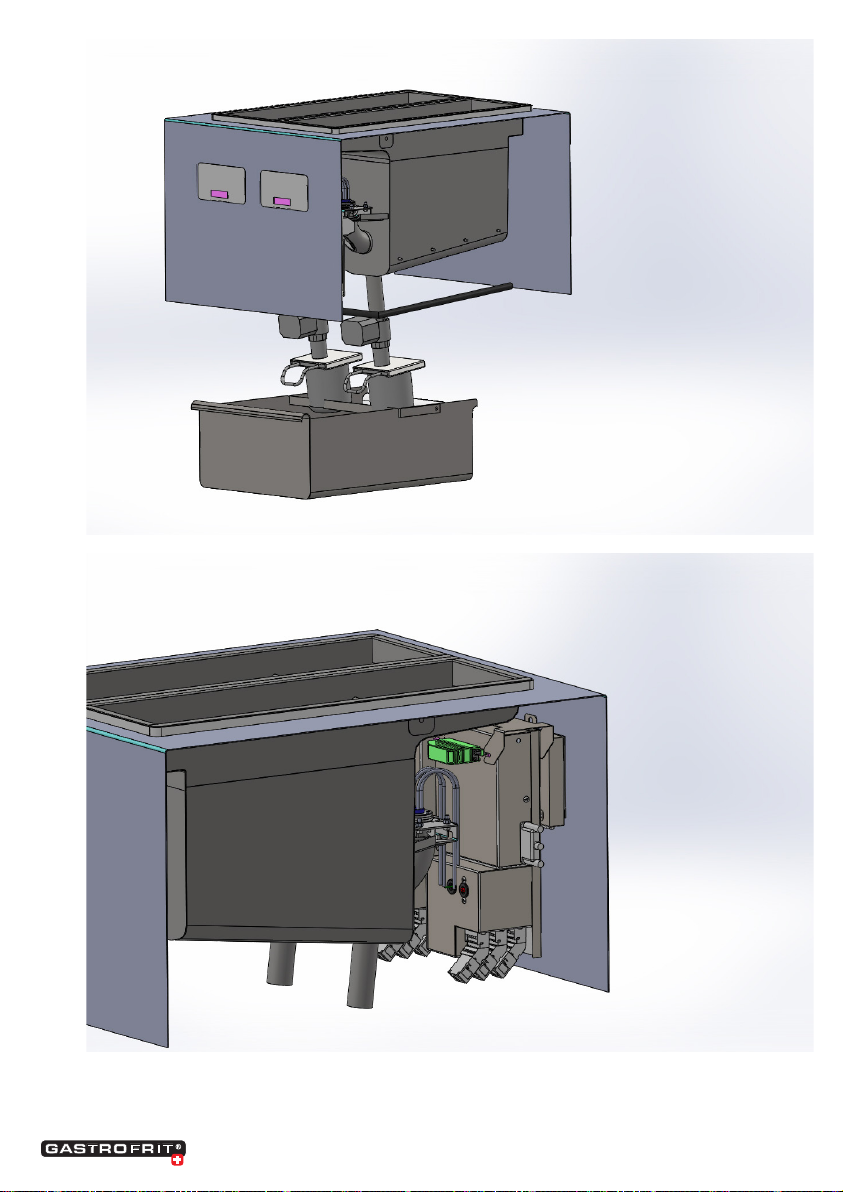
Installation description of the tting box with pan
Bracket
2 x Welding studs M4 x 8 mm
Knurled nut
Fittingbox
Installation situation / components
Pan as an example F2-400
Membrane keyboard
Built-in cover

9www.gastrofrit.ch © Switzerland Gastrofrit AG
Displaybox
Fittingbox
Installation of display box
1. 4 x Position Welko M4-8 mm symmetrically to the
cut.
2. Rectangle dimensions:
Hight 91 mm
Width 144 mm
3. Assembly seal
Apply seal
4. Assembly Display
Assembly of the display box
4x hexagon nut M4
5. close the lid
Tighten with a hexagon nut M3 with ange and
serrated lockwasher
6.

10 www.gastrofrit.ch © Switzerland Gastrofrit AG
Mounting the bracket on the built-in stove
Sheet metal for
2 x holes 0 = 8 mm
fastening the bracket
Dimensioning
• Lower edge: panel cover to cover,
64.5 mm
• Inner surface: x the cover to the
center of the bracket, 87 mm

11 www.gastrofrit.ch © Switzerland Gastrofrit AG
Position the hole = 0 8 mm symmetrically to the display box
Holes
Bracket
Hexagon nut M4
12 www.gastrofrit.ch © Switzerland Gastrofrit AG
Hang in the tting box
Tighten the knurled nut
Type Width in mm Depth in mm max. radius in mm
F-200 180 580 3
F-300 280 580 3
F-400 380 580 3
F2-400 780 580 3
TW-300 280 580 3
TW-350 580 3
TW-400 780 580 3
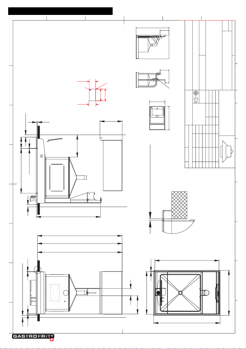
Installation dimensions pans / basins
The heating basins are placed in the corresponding
opening, the joint must be sealed with silicone. The
holes provided for frame assembly can be closed with
blind rivets or screws.
The silicone joint must be checked regularly for leaks
in order to avoid the ingress of liquids in the long
term.

13 www.gastrofrit.ch © Switzerland Gastrofrit AG
Customer service, maintenance
In the event of operational disruptions, contact
GASTROFRIT AG in Rorschach
The device may only be repaired and connected by
trained specialists.
Note (only for repair service with Gastrofrit training).
Before you fold the cover forwards, the door must be
opened! Attention! All mains circuits must be switched
o before access to the connection terminals.
Important:
With every report to the service point, please state the
type and number of the device (inside of the door).
It is recommended to enter the type and number be-
low. Regular maintenance can extend the life of your
Extend the device. With a service and maintenance
contract, you can instruct the manufacturer to check
your device every six months.
You can nd more detailed information on the service
contracts at
GASTROFRIT AG in Rorschach
Datum: _____________________
Typ: _____________________
SerieNr: _____________________
Spannung: _____________________
mit Ölcheck
mit Hubtechnik
mit Ölltrieranlage
to ll in yourself:
14 www.gastrofrit.ch © Switzerland Gastrofrit AG
91
150.5
144
R9.5
80.5
Gewindebolzen M4
auf der Rueckseite
Wasseranschluss
Schalterlochbild
Grundriss SeitenansichtFrontansicht
850
230
300 / 400
230
100
3/8" Anschluss, Ventil, Filter
Geberit Ø50
600
DETAIL B
MAßSTAB 1 :1
2mm Spaltmass allseitig
600aussen
400/300 aussen
2
280/330/380 Öffnungsmass in Tischplatte
580 Öffnungsmass in Tischplatte
310 7
Ø4.3 Senk
398 100.5
580mm Für Hubvorrichtung freihalten
200
20 min. 20
B
63
163
680mm bei lose verdrahtet ohne Ablassstutzen
710mm beiAblassstutzen kurz
750mm beiAblassstutzen normal
2
2
20mm seitlicher Abstand
A-3000022
TW 300/350/400
GASTROFRIT
Gastrofrit AG
Friteusen und Teigwarenkoch-Automaten
Weiherstr. 11a
CH-9400 Rorschach
A3
8
76
5
8
7
6
5
D
D
C
B
A
F
E
C
B
A
4
3
2
4
3
2
1:10
DIN ISO 1302
Änderung
Bl.
Blatt
Oberflächen
Bearb.
Gepr.
Norm
Tolerierung ISO 8015
Allg.Toleranzen
DIN ISO 2786
Tol. Schweissen
DIN ISO 13920-AE
Kl.Nr. BG.
Datum Name
Urspr.
Ers. f. Ers. d.
Massstab:
Name
Datum
F
E
Zust.
Format:
Urheberrecht nach DIN 34
Fabrikat: Gastrofrit
Modell: TW-300/350/400
Inhalt: 15/20 lt.
Anschlusswert u. Spannung: 10/14 KW / 15/20 A / 3x400 V
Aussenmasse: ca.300/400x600 mm
Ausfuehrung:
- Apparat komplett in rostfrei
Pastacooker electronic
seitliche Wand
Rückwand
Front
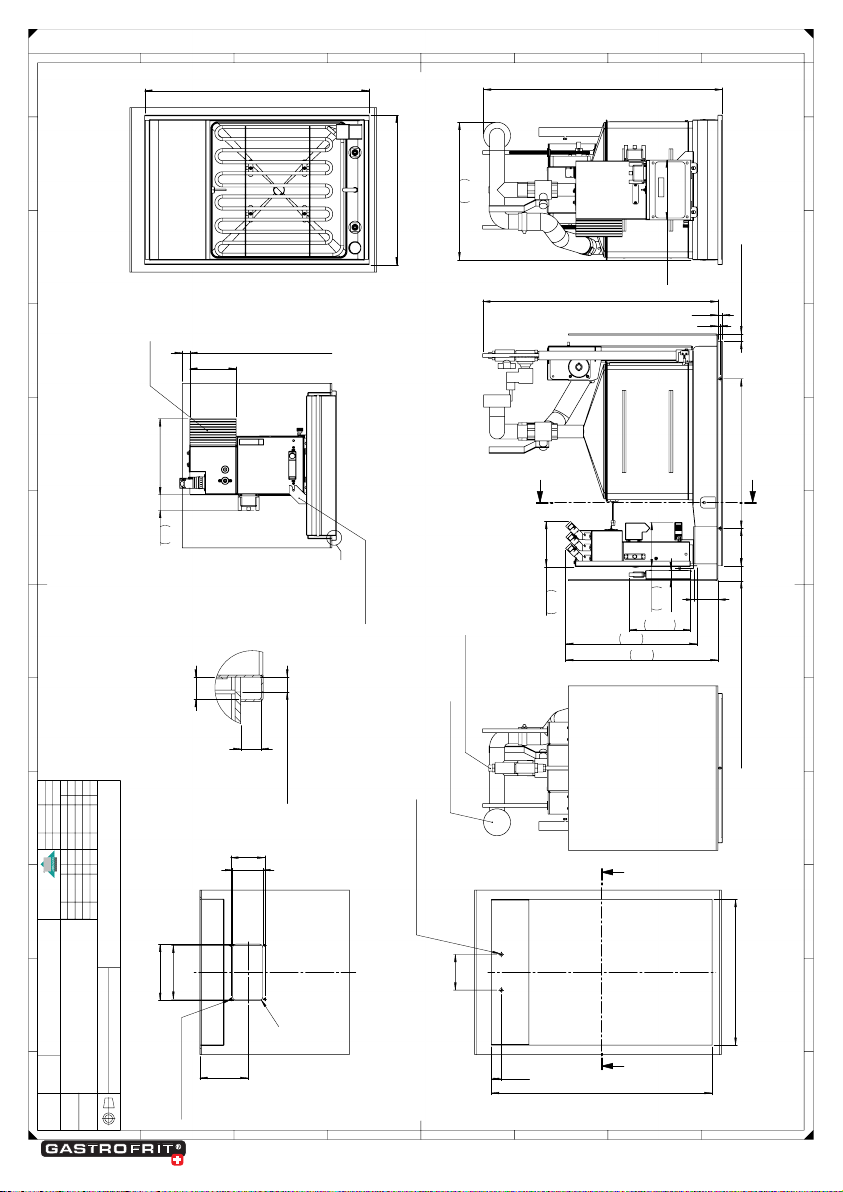
Built in drawings:
15 www.gastrofrit.ch © Switzerland Gastrofrit AG
12
11
10
9
H
G
A
B
C
D
E
F
9
10
11
12
1
2
3
4
A
B
C
E
F
D
5
6
7
8
1
2
3
4
5
6
7
8
G
H
This representation is our intellectual property. You may without our written consent at all as
neither copied nor used for the manufacture of the work or nor to be announced to a thrid
party
Gastrofrit AG Weiherstrasse 11 CH-9400
Diese Darstellung ist unser geistiges Eigentum. Sie darf ohne unsere schriftliche Zustimmung
weder irgendwie kopiert noch zur Anfertigung des Werkes gebraucht oder Drittpersonen
bekanntgegeben werden.
Gastrofrit AG Weiherstrasse 11 CH-9400
Massstab:
Format:
Material:
Datum
Änd.
Änd.
Änd.Änd.
Änd.
e
f
a
b
g
c
Blatt:
Art.Nr.:
Gastrofrit AG
Weiherstrasse 11
CH-9400 Rorschach
Änd.
Datum
Name
erst. am
Name
Änd.
h
Änd.
d
Allg. Toleranzen:
Schweissen:
Oberfläche:
Datum
Freigabe
Name
Benennung:
Zeichn.Nr.:
Gewicht:
368
639
160
400
600
95
26
590
390
B B
2xØ8mm für Halterung Steuerbox
150.4
144
91
80.4
R
9.2
128
SCHNITT B-B
4x Schweissbolzen M4x8
65
allseitig min.
20mm 400 100 40
mm für Einbau Steuerbox laut Zeichnung
5
12
629
164.5
407
118
26.4
121
351
A
A
allseitig min.
20
mm (Kühlkörper)
203 41
124
C
SCHNITT A-A
Kühlkörper
Halterung Steuerbox
12
11
8
mm Spaltmass allseitig
ANSICHT C
MAßSTAB: 1 : 1
Wasserabfluss Geberit Ø50
Wasserzulauf 3/8" Anschluss
Ausschnitt für Tischplatte
Ausschnitt für Display
Ansicht ohne Bespielblende
TW-400
os
BG Einbau-16082012
30.04.2012
/ 06
A2
05
1:5
alle Angaben ohne Gewähr
technische Änderungen vorbehalten

16 www.gastrofrit.ch © Switzerland Gastrofrit AG
12
11
10
9
H
G
A
B
C
D
E
F
9
10
11
12
1
2
3
4
A
B
C
E
F
D
5
6
7
8
1
2
3
4
5
6
7
8
G
H
This representation is our intellectual property. You may without our written consent at all as
neither copied nor used for the manufacture of the work or nor to be announced to a thrid
party
Gastrofrit AG Weiherstrasse 11 CH-9400
Diese Darstellung ist unser geistiges Eigentum. Sie darf ohne unsere schriftliche Zustimmung
weder irgendwie kopiert noch zur Anfertigung des Werkes gebraucht oder Drittpersonen
bekanntgegeben werden.
Gastrofrit AG Weiherstrasse 11 CH-9400
Massstab:
Format:
Material:
Datum
Änd.
Änd.
Änd.Änd.
Änd.
e
f
a
b
g
c
Blatt:
Art.Nr.:
Gastrofrit AG
Weiherstrasse 11
CH-9400 Rorschach
Änd.
Datum
Name
erst. am
Name
Änd.
h
Änd.
d
Allg. Toleranzen:
Schweissen:
Oberfläche:
Datum
Freigabe
Name
Benennung:
Zeichn.Nr.:
Gewicht:
637
327
342
160
allseitig min.
20mm 398 40
mm für Einbau Steuerbox laut Zeichnung
100
5
12
629
26.4
65
118
121
407
164.5
351
A
A
350
600
95
26
590
340
B B
2xØ8mm für Halterung Steuerbox
150.4
144
91
80.4
128
SCHNITT B-B
Ausschnitt für Tischplatte
Ausschnitt für Display
4x Schweissbolzen M4x8
203 41
124
allseitig min.
20
mm (Kühlkörper)
C
SCHNITT A-A
Kühlkörper
Halterung Steuerbox
8
mm Spaltmass allseitig
11
12
ANSICHT C
MAßSTAB: 1 : 1
Wasserabfluss Geberit Ø50
Wasserzulauf 3/8" Anschluss
Ansicht ohne Bespielblende
TW-350
os
BG Einbau-16082012
30.04.2012
/ 06
A2
06
1:5
alle Angaben ohne Gewähr
technische Änderungen vorbehalten

17 www.gastrofrit.ch © Switzerland Gastrofrit AG
12
11
10
9
H
G
A
B
C
D
E
F
9
10
11
12
1
2
3
4
A
B
C
E
F
D
5
6
7
8
1
2
3
4
5
6
7
8
G
H
This representation is our intellectual property. You may without our written consent at all as
neither copied nor used for the manufacture of the work or nor to be announced to a thrid
party
Gastrofrit AG Weiherstrasse 11 CH-9400
Diese Darstellung ist unser geistiges Eigentum. Sie darf ohne unsere schriftliche Zustimmung
weder irgendwie kopiert noch zur Anfertigung des Werkes gebraucht oder Drittpersonen
bekanntgegeben werden.
Gastrofrit AG Weiherstrasse 11 CH-9400
Massstab:
Format:
Material:
Datum
Änd.
Änd.
Änd.Änd.
Änd.
e
f
a
b
g
c
Blatt:
Art.Nr.:
Gastrofrit AG
Weiherstrasse 11, CH-9400 Rorschach
Änd.
Datum
Name
erst. am
Name
Änd.
h
Änd.
d
Allg. Toleranzen:
Schweissen:
Oberfläche:
Datum
Freigabe
Name
Benennung:
Zeichn.Nr.:
Gewicht:
531
178
191
802
13.3
allseitig min. 20mm
56mm für Einbau Steuerbox laut Zeichnung
480
240
67.00
A
A
E
E
400
600
816
157.00
Ansicht ohne Beispielblende
214.00
61
157.00
SCHNITT A-A
380
580
EE
Ausschnitt für Tischplatte
128.00
48.00
196.03
125.00
80.40
150.40
R9.20
198.40
SCHNITT E-E
8x Schweissbolzen M4x8
Ausschnitt für Display
380
F
SCHNITT E-E
2.00
DETAIL F
MAßSTAB 1 : 1
alle Angaben ohne Gewähr
technische Änderungen vorbehalten
BG Einbaugerät
18.02.2021
/ 01
A2
01
1:5
ELM2-400
19.02.2021
Ilie R.
Ilie R.
-
18 www.gastrofrit.ch © Switzerland Gastrofrit AG

19 www.gastrofrit.ch © Switzerland Gastrofrit AG
12
11
10
9
H
G
A
B
C
D
E
F
9
10
11
12
1
2
3
4
A
B
C
E
F
D
5
6
7
8
1
2
3
4
5
6
7
8
G
H
This representation is our intellectual property. You may without our written consent at all as
neither copied nor used for the manufacture of the work or nor to be announced to a thrid
party
Gastrofrit AG Weiherstrasse 11 CH-9400
Diese Darstellung ist unser geistiges Eigentum. Sie darf ohne unsere schriftliche Zustimmung
weder irgendwie kopiert noch zur Anfertigung des Werkes gebraucht oder Drittpersonen
bekanntgegeben werden.
Gastrofrit AG Weiherstrasse 11 CH-9400
-0.2
-0.5
+0.5
+0.2
unbemasste
Werkstückkanten
DIN ISO 13715
Massstab:
Format:
Material:
Datum
Änd.
Änd.
Änd.Änd.
Änd.
e
f
a
b
g
c
Blatt:
Art.Nr.:
Gastrofrit AG
Weiherstrasse 11, CH-9400 Rorschach
Änd.
Datum
Name
erst. am
Name
Änd.
h
Änd.
d
Allg. Toleranzen:
Schweissen:
Oberfläche:
Datum
Freigabe
Name
Benennung:
Zeichn.Nr.:
Gewicht:
531
178
192
802
13.3
allseitig min. 20mm
56mm für Einbau Steuerbox laut Zeichnung
479.50
67.00
240
155
A
A
E
E
811
157.00
Ansicht ohne Bespielblende
280
578
B B
Ausschitt für Tischplatte
196
125
118
80.40
150.40
R9.20
128.00
SCHNITT B-B
Ausschitt für Display
4x Schweissbolzen M4x8
61
214.00
157.00
SCHNITT A-A
300
600
280
F
SCHNITT E-E
2.00
DETAIL F
MAßSTAB 1 : 1
Alle Angaben ohne Gewähr
technische änderungen vorbehalten
ELM-300
-
-
-
Ilie R.
Ilie R.
17.02.2021
BG Einbaugerät
16.02.2021
/ 01
A2
01
1:5

20 www.gastrofrit.ch © Switzerland Gastrofrit AG
12
11
10
9
H
G
A
B
C
D
E
F
9
10
11
12
1
2
3
4
A
B
C
E
F
D
5
6
7
8
1
2
3
4
5
6
7
8
G
H
This representation is our intellectual property. You may without our written consent at all as
neither copied nor used for the manufacture of the work or nor to be announced to a thrid
party
Gastrofrit AG Weiherstrasse 11 CH-9400
Diese Darstellung ist unser geistiges Eigentum. Sie darf ohne unsere schriftliche Zustimmung
weder irgendwie kopiert noch zur Anfertigung des Werkes gebraucht oder Drittpersonen
bekanntgegeben werden.
Gastrofrit AG Weiherstrasse 11 CH-9400
-0.2
-0.5
+0.5
+0.2
unbemasste
Werkstückkanten
DIN ISO 13715
Massstab:
Format:
Material:
Datum
Änd.
Änd.
Änd.Änd.
Änd.
e
f
a
b
g
c
Blatt:
Art.Nr.:
Gastrofrit AG
Weiherstrasse 11, CH-9400 Rorschach
Änd.
Datum
Name
erst. am
Name
Änd.
h
Änd.
d
Allg. Toleranzen:
Schweissen:
Oberfläche:
Datum
Freigabe
Name
Benennung:
Zeichn.Nr.:
Gewicht:
531
178
192
802
619
433
13.3
allseitig min. 20mm
56mm für Einbau Steuerbox laut Zeichnung
392
153
32
155
A
A
E
E
811
157.00
Ansicht ohne Bespielblende
280
578
B B
Ausschitt für Tischplatte
91
144
144
80.40
150.40
R9.20
128.00
SCHNITT B-B
Ausschitt für Display
4x Schweissbolzen M4x8
157.00
351
61
SCHNITT A-A
300
600
280
F
SCHNITT E-E
2.00
DETAIL F
MAßSTAB 1 : 1
G
G
351
41
51
157
SCHNITT G-G
Halterung Steuerbox
Alle Angaben ohne Gewähr
technische änderungen vorbehalten
F-300
-
-
-
Ilie R.
Ilie R.
17.02.2021
BG Einbaugerät
16.02.2021
/ 01
A2
01
1:5
This manual suits for next models
21
Table of contents


