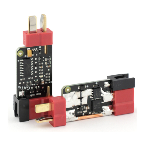
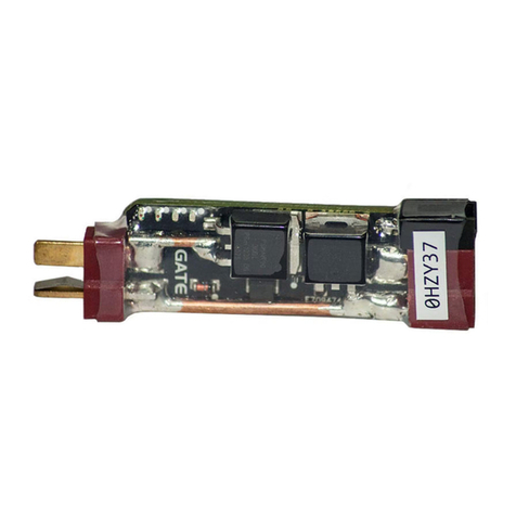
Gate WARFET User manual

User Guide
WARFET
Last update on December 14, 2015 www.gatee.eu

WARFET User Guide WARFET User Guide
GATE Menet, Wojtak Sp. J. does not take any responsibility for
damages, injuries and accidents resulting in the use of WARFET or
Air Electric Gun with installed WARFET.
Notice
Information contained in this document is subject to updating without
notice.
FOR YOUR OWN SAFETY, PLEASE READ THIS USER GUIDE
CAREFULLY BEFORE INSTALLING THE AEG CONTROL SYSTEM
Safety Summary
THE DEVICES COVERS MUST NOT BE REMOVED BY THE USER
DANGER!
Short-circuiting of battery packs. Caution must be exercised to
prevent short circuiting the battery as the consequences can be very
dangerous.
FOR YOUR SAFETY
We recommend that this product should be installed by an experienced
airsoft service.
WARNING: Before starting installation process, please ensure that your
AEG is empty and there are no BBs inside.
WARNING: Always use a fuse between the battery and the controller.
WARNING: Incorrectly connecting positive and negative battery
terminals will cause immediate damage to the unit and it can lead to fire.
NOTE:
Please check if you have downloaded the latest manual from the
Technical Support section of our website: www.gatee.eu.
The Product Warranty Form is also available on our website:
http://www.gatee.eu/en/rma-2
In case you have any difficulties while installing or using this product, we
PRODUCT DISPOSAL INSTRUCTIONS
The symbol shown here means that the product is classed as Electrical or Electronic Equipment
and should not be disposed with other household and commercial waste at the end of its
working life. The Waste of Electrical and Electronic Equipment (WEEE Directive 2002/96/EU)
has been put in place to recycle products using best available recovery and recycling
techniques to minimize the impact on the environment. Purchasers shall take any old electrical
equipment to waste recycling public centers or points of sale.
CERTIFICATE OF CONFORMITY
GATE Menet, Wojtak Sp. J. hereby declares under our sole responsibility that the product GATE
WARFET is in conformity with the essential requirements of the following Directives:
EMC DIRECTIVE 2014/30/UE
This product has been certified as RoHS Compliant.
-2- -3-

WARFET User Guide WARFET User Guide
GATE Menet, Wojtak Sp. J. does not take any responsibility for
damages, injuries and accidents resulting in the use of WARFET or
Air Electric Gun with installed WARFET.
Notice
Information contained in this document is subject to updating without
notice.
FOR YOUR OWN SAFETY, PLEASE READ THIS USER GUIDE
CAREFULLY BEFORE INSTALLING THE AEG CONTROL SYSTEM
Safety Summary
THE DEVICES COVERS MUST NOT BE REMOVED BY THE USER
DANGER!
Short-circuiting of battery packs. Caution must be exercised to
prevent short circuiting the battery as the consequences can be very
dangerous.
FOR YOUR SAFETY
We recommend that this product should be installed by an experienced
airsoft service.
WARNING: Before starting installation process, please ensure that your
AEG is empty and there are no BBs inside.
WARNING: Always use a fuse between the battery and the controller.
WARNING: Incorrectly connecting positive and negative battery
terminals will cause immediate damage to the unit and it can lead to fire.
NOTE:
Please check if you have downloaded the latest manual from the
Technical Support section of our website: www.gatee.eu.
The Product Warranty Form is also available on our website:
http://www.gatee.eu/en/rma-2
In case you have any difficulties while installing or using this product, we
recommend to email us at [email protected].
PRODUCT DISPOSAL INSTRUCTIONS
The symbol shown here means that the product is classed as Electrical or Electronic Equipment
and should not be disposed with other household and commercial waste at the end of its
working life. The Waste of Electrical and Electronic Equipment (WEEE Directive 2002/96/EU)
has been put in place to recycle products using best available recovery and recycling
techniques to minimize the impact on the environment. Purchasers shall take any old electrical
equipment to waste recycling public centers or points of sale.
CERTIFICATE OF CONFORMITY
GATE Menet, Wojtak Sp. J. hereby declares under our sole responsibility that the product GATE
WARFET is in conformity with the essential requirements of the following Directives:
EMC DIRECTIVE 2014/30/UE
This product has been certified as RoHS Compliant.
-2- -3-

WARFET User Guide WARFET User Guide
Table of Contents
Safety Summary
Table of Contents
I. Overview
Features
AEG Controller parameters
Tactical Programming Card overview
Tactical Programming Card parameters
Key functions
Package contents
II. Plug & Play
III. Hardwired Installation
AEG standard installation diagram
• Installation of WARFET without replacement of wires
• Installation of WARFET with replacement of wires
IV. Tactical Programming
V. Troubleshooting
VI. GATE Limited Warranty PolicyCard usage
2
4
5
5
6
6
7
8
12
13
15
15
16
16
18
20
22
I. Overview
WARFET is GATE's most advanced AEG Control System. It has 20 functions
and almost 6 million possible configurations. The outstanding Tactical
Programming Card provides you with very easy access to the AEG Controller
settings. Thanks to the PRE-COCKING and SMART TRIGGER functions, you
can achieve a trigger response similar to a real gun. The Programmable
Burst (1-5 rounds) enables you to fire a pre-determined number of BBs,
which is very useful in MILSLIM and for using low-caps. Another function is
ROF Control, which allows you to reduce ROF, so you can use strong LiPo
batteries, and still have ROF just like in a real rifle. If your AEG becomes
jammed, the SMART FUSE protects the battery and the motor against
damage. It also prevents deep battery drain. Moreover, with WARFET you
get: MOSFET, ON/OFF ACTIVE BRAKE, BUILT-IN SELF TEST, DEBOUNCING,
and more. Many useful functions, great electrical specifications and
conformal coating (military specifications: MIL-V-173C) make the AEG
Control System able to meet the needs of most experienced airsoft players.
Features
źUser-friendly configuration via the Tactical Programming Card
źSturdy and super-small size AEG Controller
źCompatibility with the strongest AEG replicas and batteries (ready to
work with LiPo 14.8V, 5000 mAh, 60C)
źTested with car batteries
źSuper-easy installation - thanks to the Mini Tamiya adapters, you can
connect WARFET to the original (stock) installation
źIt can work with most built-in MOSFETs
źWith stock wiring, WARFET reduces melting switch assemblies
-4- -5-

WARFET User Guide WARFET User Guide
źIn hardwired installation, WARFET draws the energy from the battery
directly to the motor, bypassing the mechanical trigger contacts
źResistant to atmospheric conditions (military specifications: MIL-V-
173C)
źDeep-drain protection for 7.4V, 11.1V, 14.8V LiPoly and 9.6V, 12.8V
LiFePO4
źImproves battery life, ROF, spring life and gearbox reliability
AEG Controller parameters
źWide range of supply voltage:3-17V
źProtection against short-circuits:up to 1000A
źIncredibly low current consumption on stand-by: 0.2mA
źUltra low resistance:2mΩ
źDimensions: 56x20x9mm
źWeight:9.4g
Tactical Programming Card overview
The outstanding Tactical Programming Card provides you with very easy
access to the AEG Controller settings. All you need to do is to connect the
Tactical Programming Card between the battery and the controller. A big
advantage is that there is no need to use any additional wires. The AEG
Controller can be fitted out of view in your AEG, and you still have easy
access to its settings. The Tactical Programming Card communicates with
the AEG Controller and displays the most recently saved settings. You can
simply change them using three buttons.
Tactical Programming Card parameters:
źSupply voltage: 5-17V
źDimensions: 67x53x7mm
źWeight: 27.3g
źNumber of LEDs: 29
źNumber of buttons: 3
-6- -7-

Key functions:
TACTICAL
PROGRAMMING
CARD
The outstanding Tactical Programming Card provides you with very
easy access to the AEG Controller settings. All you need to do is
connect the Tactical Programming Card between the battery and the
Controller.
Super-easy installation, just plug and play. No soldering required. All
you need to do is to connect the battery and the rifle to the AEG
Controller.
The burst enables you to shoot a pre-determined number of BBs (1-5
rounds), which is very useful in MILSLIM and when using low-caps.
You can transform AUTO MODE to BURST MODE or SEMI MODE to
BURST MODE*. The Tactical Programming Card allows you to set the
burst time. The AEG Controller automatically corrects the burst time
according to the voltage level of the battery.
*SEMI to BURST in modified installations only.
It enables lossless reduction of the rifle's rate of fire, so you can use
strong LiPo batteries, and still have ROF like in a real gun.
We know how vital the fast trigger response is during combat. This is
why we have developed the Smart Trigger function. It enables you to
achieve a faster trigger response. It works with the ROF Control
system. During the first shot, the microprocessor sets the ROF Control
to 100%. After the first shot, it switches to a previously programmed
value (e.g. 50%). As a consequence, the first shot is fired at a full rate of
fire, and subsequent shots at a reduced ROF. The best results can be
achieved by using a battery with a higher than standard voltage. For
example, if you use a 7.4V battery, you can replace it with 11.1V. In this
way, you will achieve a faster trigger response with the same rate of
fire as with a standard battery. The Smart Trigger is most effective
when the Burst time is set at 3 rounds.
Protection against Over-Discharge of the Battery. Modern LiPo and
LiFe batteries are very sensitive to over-discharge. If you do not want
to damage the battery and you care about its service life, this
protection is indispensable. The microprocessor monitors the battery
voltage constantly. When the voltage drops down to a critical level,
the Controller will not allow firing.
The function gives you the option to program your fire selector. There
are five operating modes:
- STOCK WIRING SEMI/AUTO
- STOCK WIRING SEMI/BURST
- MODIFIED WIRING SEMI/AUTO
- MODIFIED WIRING SEMI/BURST
- MODIFIED WIRING BURST/AUTO
Victory in the game is often a matter of fractions of seconds. Thanks to
the PRE-COCKING, you gain a trigger reaction similar to a real gun. It
allows for initial spring compression, which speeds up the trigger
response significantly. You can set the time of PRE-COCKING using the
Tactical Programming Card.
There are two PRE-COCKING MODES:
1) AUTO MODE – the spring is automatically compressed after each
shot,
2) TRIGGER MODE – the first trigger action compresses the spring,
and the second trigger action fires the shot.
Please note: using PRE-COCKING increases wear and tear on the gearbox. PRE-
COCKING is designed for SEMI mode. In the AUTO mode, it can result in blank shots.
PRECOCKING
Plug&Play
1-5rd Burst
CONFIGURABLE
FIRE
SELECTOR
WARFET User Guide WARFET User Guide
-8- -9-

Key functions:
TACTICAL
PROGRAMMING
CARD
The outstanding Tactical Programming Card provides you with very
easy access to the AEG Controller settings. All you need to do is
connect the Tactical Programming Card between the battery and the
Controller.
Super-easy installation, just plug and play. No soldering required. All
you need to do is to connect the battery and the rifle to the AEG
Controller.
The burst enables you to shoot a pre-determined number of BBs (1-5
rounds), which is very useful in MILSLIM and when using low-caps.
You can transform AUTO MODE to BURST MODE or SEMI MODE to
BURST MODE*. The Tactical Programming Card allows you to set the
burst time. The AEG Controller automatically corrects the burst time
according to the voltage level of the battery.
*SEMI to BURST in modified installations only.
It enables lossless reduction of the rifle's rate of fire, so you can use
strong LiPo batteries, and still have ROF like in a real gun.
We know how vital the fast trigger response is during combat. This is
why we have developed the Smart Trigger function. It enables you to
achieve a faster trigger response. It works with the ROF Control
system. During the first shot, the microprocessor sets the ROF Control
to 100%. After the first shot, it switches to a previously programmed
value (e.g. 50%). As a consequence, the first shot is fired at a full rate of
fire, and subsequent shots at a reduced ROF. The best results can be
achieved by using a battery with a higher than standard voltage. For
example, if you use a 7.4V battery, you can replace it with 11.1V. In this
way, you will achieve a faster trigger response with the same rate of
fire as with a standard battery. The Smart Trigger is most effective
when the Burst time is set at 3 rounds.
Protection against Over-Discharge of the Battery. Modern LiPo and
LiFe batteries are very sensitive to over-discharge. If you do not want
to damage the battery and you care about its service life, this
protection is indispensable. The microprocessor monitors the battery
voltage constantly. When the voltage drops down to a critical level,
the Controller will not allow firing.
The function gives you the option to program your fire selector. There
are five operating modes:
- STOCK WIRING SEMI/AUTO
- STOCK WIRING SEMI/BURST
- MODIFIED WIRING SEMI/AUTO
- MODIFIED WIRING SEMI/BURST
- MODIFIED WIRING BURST/AUTO
Victory in the game is often a matter of fractions of seconds. Thanks to
the PRE-COCKING, you gain a trigger reaction similar to a real gun. It
allows for initial spring compression, which speeds up the trigger
response significantly. You can set the time of PRE-COCKING using the
Tactical Programming Card.
There are two PRE-COCKING MODES:
1) AUTO MODE – the spring is automatically compressed after each
shot,
2) TRIGGER MODE – the first trigger action compresses the spring,
and the second trigger action fires the shot.
Please note: using PRE-COCKING increases wear and tear on the gearbox. PRE-
COCKING is designed for SEMI mode. In the AUTO mode, it can result in blank shots.
PRECOCKING
Plug&Play
1-5rd Burst
CONFIGURABLE
FIRE
SELECTOR
WARFET User Guide WARFET User Guide
-8- -9-

WARFET User Guide WARFET User Guide
The Controller provides you with the opportunity to decide if you
want to use the Active Brake function. If you do not need this, you can
turn it off easily. It will lead to improving the lifespan of your motor.
Do you care about realism? Would you like to increase the life of the
gearbox? Does your rifle have such a high rate of fire that you are not
able to make a single shot? The Active Brake sorts things out. In SEMI
Mode, the brake does not allow for compressing a piston after a shot.
The piston will stop in the front position which eliminates
unnecessary stresses, increasing the service life of the gearbox and its
parts. This is important, especially with an AEG power upgrade. After
releasing the trigger, the rifle immediately stops firing. So, you gain
more realism and, additionally, you do not waste your precious
ammunition.
The new AEG Controller should never let you down on the battlefield.
It is the best electronic fuse. The AEG Controller has a true current
sensor. A combination of current, voltage and temperature
measurements makes your AEG installation highly reliable. If your
rifle becomes jammed, the SMART FUSE protects motor and battery
against damage. Overheating, overloading or short-circuiting of the
electrical system should not damage the Controller.
SMART
FUSE
SMART
FUSE
ON/OFF
ACTIVE BRAKE
This provides full compatibility with the micro-switches. It ensures
full resistance to contact bounce (vibration). You gain a bigger ROF, a
faster trigger response and your MOSFET is less prone to overheating.
It allows you to quickly check whether the AEG Controller works
properly. If you have problems with your AEG, the BUILT-IN SELF-TEST
allows you to check that the problem is not caused by the Controller.
The advent of modern transistors and microcontroller has enabled us
to create the smallest and most reliable AEG Controller on the market.
DARK MODE allows you to turn off the LED indicator which glows
green when a gun is firing. This function is especially useful during
night games.
Thanks to its special conformal coating, it is resistant to atmospheric
conditions (Military Specification MIL-V-173C).
The system can be used with batteries up to 14.8V LI-PO. Minimum
operating voltage is 3V and maximum voltage is 17V.
Do you want to achieve a higher rate of fire and faster trigger
response? Are you planning a power upgrade of your rifle? In that
case, you need a MOSFET. It targets the energy from the battery
directly to the motor, bypassing the mechanical trigger contacts. As a
result, you gain a higher rate of fire of the rifle and a faster trigger
response, and the contacts are protected against burn out.
DEBOUNCING
BUILT-IN
SELF-TEST
DARK
MODE
COATING
Li-Po
Ready
14.8V
Thanks to the Mini Tamiya Adapters included in kit, you will be able to
smoothly connect WARFET to your original installation.
It makes easier starting your adventure with WARFET. The quickstart
contains basic information and hints.
In the case of a hardwired installation, the Controller draws the power
from the battery directly to the motor, bypassing the mechanical
trigger contacts. This requires a modification of the AEG installation.
HARDWIRED
MINI TAMIYA READY
PRINTED
QUICKSTART
-10- -11-

WARFET User Guide WARFET User Guide
Package contents
Check the product box for fallowing items:
1) Tactical Programming Card
2) AEG Controller
3) Battery Mini Tamiya adapter
4) AEG Mini Tamiya adapter
5) Pair of Deans-T Connectors
6) Single Trigger Wire
7) Double Trigger Wire
8) Quickstart Guide
3
4
5
6
7
II. Plug & Play Installation
WARFET
(CONTROLLER)
Battery
Mini Tamiya
adapter
AEG
Mini Tamiya
adapter
WARFET
WARFET
WARNING!
CHECK POLARITY!
Incorrectly connecting positive and negative
battery terminals will cause immediate damage to
the unit and it can lead to fire. For your own safety,
always use a fuse between Battery and Controller.
Battery pack
Battery
7.2 - 14.8V
Steps:
1. If necessary, connect Mini Tamiya adapters (included in the kit) to WARFET.
2. Connect the battery to WARFET. The LED indicator glows BLUE for 1
second.
-12- -13-

WARFET
WARFET User Guide WARFET User Guide
3. Connect the AEG to WARFET.
4. Pull the trigger. The AEG should start firing. While firing, the LED indicator
should glow GREEN*. If the AEG is not firing and/or LED indicator glows
different colour please check troubleshooting (page 20).
*only when DARK MODE OFF
5. To change settings go to chapter IV (Programming Card usage).
III. Hardwired Installation
Battery
7.2 - 14.8V
AEG Motor
AEG Stock Wiring
Battery
7.2 - 14.8V
AEG Motor
2. Adapt AEG installation.
To adapt the standard AEG installation to work with WARFET in hardwired
mode it is necessary to get to the trigger contacts. In the case of GB v2
contacts are located inside a gearbox. With a version 3 gearbox, the
installation will be easier because the contacts are on the outside of the
gearbox. Please consult a local airsoft technician if you have never
disassembled a gearbox before or if you have any installation concerns.
these
A B
(Fig 1 – Standard AEG wiring scheme)
Steps:
1. Switch operating mode.
To be able to work with Hardwired Installation, necessarily go to chapter IV
(Programming Card usage, p. 18) and switch operating mode to MODIFIED
WIRING.
STOCK WIRING MODIFIED WIRING
SEMI
AUTO
SEMI
BURST
BURST
AUTO
SEMI
AUTO
SEMI
BURST
-14- -15-

WARFET User Guide WARFET User Guide
AEG Motor
WARFET
Battery
7.2 - 14.8V
AEG Motor
WARFET
Battery
7.2 - 14.8V
(Fig 2 – Connection-modification scheme)
(Fig 3 – Complete re-wiring scheme)
top pin
b) Installation of WARFET with replacement of wires.
Replacing the existing AEG wiring with high-quality, low-resistance wiring in
conjunction with the installation of a MOSFET allows for the ultimate in
system efficiency. 16 awg or thicker wire is recommended. Solder the
dualtrigger wire (No. 7 – provided in the kit) to the trigger contacts. The
trigger wire is very thin because it handles very low current and it is only
used for switch-detection. Now connect the device between the battery and
motor. Do not forget about the trigger wire.
single trigger wire
(No. 6 – provided in the kit)
double trigger wire
(No. 7 – provided in the kit)
Your AEG is firing without pulling the trigger? Go to chapter IV
and switch operating mode to MODIFIED WIRING.
a) Installation of WARFET without replacement of wires. Using this
method, the original wiring is kept intact, and the connections are modified.
Referencing Fig 1, de-solder A wire from the one of the trigger contacts and
then solder it to the B wire. It does not matter which wire you disconnect
from the trigger switches, just join the two wires together at one terminal. In
the place of the A wire, solder the additional single trigger wire (No. 6 –
provided in the kit). The trigger wire is very thin because it handles very low
current and it is only used for switch-detection. Now connect the device
between the battery and AEG. Do not forget about the trigger wire. Connect
it to the top pin.
-16- -17-

IV. Tactical Programming Card usage
WARFET User Guide WARFET User Guide
Fig 4
Battery
7.2 - 14.8V
50 60 70 80 90 100
SHORT LONG
BURST
TIME
STOCK WIRING MODIFIED WIRING
OFF TRIGGER AUTO
PRE-COCKING
BATTERY PROTECTION
ROF CONTROL
PRE-COCKING
BOOST
ACTIVE BRAKE
SMART TRIGGER
DARK MODE
OFF ON OFF ONOFF ON
7.4V 11.1V 14.8V 9.9V 13.2VOFF
LESS MORE
NEXT
LOAD DEFAULT DEMO
SEMI
AUTO
SEMI
BURST
BURST
AUTO
SEMI
AUTO
SEMI
BURST
PROGRAMMING CARD
BATTERY CONNECTOR CONTROLLER CONNECTOR
BUTTON RIGHT
LEDs
BUTTON NEXT
RED DISPLAY
BLUE DISPLAY
BUTTON LEFT
RED ICON
BLUE ICON
WARFET
Instructions:
1. Connect the battery to the Programming Card. The LEDs light on and
start blinking (Fig 4).
2. Connect the Controller to the Programming Card. All current settings
are displayed on the corresponding LEDs (Fig 5).
3. When the BLUE ICON is on, check only on the blue display of the
Programming Card (Fig 5).
When the RED ICON is on, check only on the red display of the
Programming Card (Fig 6).
4. Click and hold button NEXT to watch DEMO.
5. Click button NEXT to switch between functions and displays.
6. Click buttons LEFT or RIGHT to switch options.
7. Click and hold buttons LEFT or RIGHT to switch options more quickly.
8. Before firing, disconnect the Programming Card and connect the
Controller to the battery.
9. All the settings are saved automatically.
10. Click and hold buttons LEFT and RIGHT to load default settings.
50 60 70 80 90 100
SHORT LONG
BURST
TIME
STOCK WIRING MODIFIED WIRING
OFF TRIGGER AUTO
PRE-COCKING
BATTERY PROTECTION
ROF CONTROL
PRE-COCKING
BOOST
ACTIVE BRAKE
SMART TRIGGER
DARK MODE
OFF ON OFF ONOFF ON
7.4V 11.1V 14.8V 9.9V 13.2VOFF
LESS MORE
SEMI
AUTO
SEMI
BURST
BURST
AUTO
SEMI
AUTO
SEMI
BURST
50 60 70 80 90 100
SHORT LONG
BURST
TIME
OFF TRIGGER AUTO
PRE-COCKING
BATTERY PROTECTION
ROF CONTROL
PRE-COCKING
BOOST
ACTIVE BRAKE
SMART TRIGGER
DARK MODE
OFF ON OFF ONOFF ON
7.4V 11.1V 14.8V 9.9V 13.2VOFF
LESS MORE
SEMI
AUTO
SEMI
BURST
BURST
AUTO
SEMI
AUTO
SEMI
BURST
PRE-COCKING
BOOST
maximum value
BLUE ICON on
DARK MODE - OFF
RED ICON on
BURST TIME
minimum value
How to read settings? Take a look at the examples below:
corresponding LED
STOCK WIRING
SEMI/AUTO
Fig 5
Fig 6
STOCK WIRING MODIFIED WIRING
Example 1. The BLUE ICON glows. Check only on the blue display.
PRE-COCKING - OFF
ACTIVE BRAKE - OFF
SMART TIGGER - OFF
DARK MODE - OFF
BATTERY PROTECTION - 7.4
ROF CONTROL - 100%
STOCK WIRING - SEMI AUTO
Example 2. The RED ICON glows. Check only on the red display.
PRE-COCKING BOOST - maximum value
BURST TIME - minimum value
-18- -19-

WARFET User Guide WARFET User Guide
TROUBLESHOOTING
MALFUNCTION POSSIBLE REASON
Ţ PLUG&PLAY INSTALLATION Ţ
WHAT TO DO
After connecting the battery to the
Controller, the LED indicator does
not light on. WARFET does not
react.
After a trigger action, the LED
indicator blinks red. Even though
the motor is connected, the AEG
does not fire.
After a trigger action, the LED
indicator blinks green shortly. Even
though the motor is connected, the
AEG does not fire.
After a trigger action, the LED
indicator glows red. Even though
the motor is connected, the AEG
does not fire.
The WARFET does not react to
any trigger action. The AEG does
not fire.
The battery is discharged.
No contact with the battery.
A permanent damage to the
Controller.
A weak contact with the contact
cube.
A weak contact with the motor
connectors.
The motor wires are damaged.
The motor windings are damaged.
The battery is discharged.
The BATTERY PROTECTION
function is badly programmed.
No contact with the battery.
A short-circuit between the signal
wires and the motor wires (in
Hardwired Installation only).
A short-circuit of the motor wires.
A short-circuit of the motor.
The battery is discharged.
No contact in the switch assembly.
No contact with the motor
connectors.
The motor wires are broken.
The motor windings are broken.
Charge the battery.
Clean the battery connector.
Clean the Controller connector.
Contact GATE Technical Support:
Clean the contact cube or replace
it with a new one.
Clean the motor connector in the
Controller.
Check the motor connectors.
Check and repair the motor wires.
Repair the motor or replace it with
a new one.
Charge the battery.
Program the BATTERY
PROTECTION function correctly.
Clean the battery connector.
Clean the WARFET connector.
Check and repair the signal wires
insulation and the motor wires
insulation.
Connect another motor.
Charge the battery.
Clean the switch assembly.
Clean the motor connector in the
Controller.
Check the motor connectors.
Repair the wires.
Repair the motor or replace it with
a new one.
Ţ HARDWIRED INSTALATIONŢ
After a trigger action, the LED
indicator glows yellow. Even
though the motor is connected, the
AEG does not fire.
After connecting the motor to the
Controller, the AEG starts firing
immediately.
After connecting the motor to the
Controller, the AEG starts firing
immediately.
The WARFET does not react to
any trigger action. The AEG does
not fire.
After a trigger action, the LED
indicator glows yellow. Even
though the motor is connected, the
AEG does not fire.
No contact with the motor.
The motor wires are broken.
The motor windings are broken.
A short-circuit in the
assembly.
switch
The WARFET is set on the Stock
Wiring mode.
The WARFET is set on the Stock
Wiring mode.
No contact with the Signal Socket.
No contact with the switch
assembly.
A short-circuit or break in the
trigger wire (from the switch
assembly).
The WARFET is set on the
Modified Wiring mode.
Clean the Controller connector.
Check and repair the motor wires.
Repair the motor or replace it with
a new one.
Check and repair the
assembly.
switch
Reprogram the WARFET to the
Modified Wiring mode.
Reprogram the WARFET to the
Modified Wiring mode.
Clean the Controller Signal
Socket.
Clean the switch assembly or
replace it with a new one.
Repair the trigger wire or replace it
with a new one.
Reprogram the WARFET for the
Stock Wiring mode.
-20- -21-
Other manuals for WARFET
1
Table of contents
Other Gate Controllers manuals
Popular Controllers manuals by other brands

Motec
Motec LTC user manual

Enovation Controls
Enovation Controls Murphy EMS PRO LITE Installation and operation manual

Pepperl+Fuchs
Pepperl+Fuchs KFD0-SD2-Ex2.1 45 Series manual

ABB
ABB MotiFlex e180 Application guide

Keating Of Chicago
Keating Of Chicago UA Flame Master Lo-Temp Griddle Service instructions

Honeywell
Honeywell M6410A Specification data