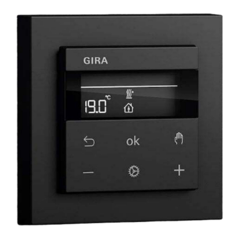
Gira G1 User manual

230 V 2067 05 / 2067 12
PoE 2069 05 / 2069 12
24 V 2077 05 / 2077 12
GiraG1
[EN] Installation instructions

2Gira G1 Installation instructions
1 For your safety p. 3
1.1 Area of application p. 4
1.2 General safety instructions p. 4
2 Device description p. 7
2.1 Flush-mounted connection
module p. 8
2.1.1 Flush-mounted connection
module PoE p. 8
2.1.2 Flush-mounted connection
module 230 V p. 9
2.1.3 Flush-mounted connection
module 24 V p. 9
2.2 Holding frame p. 10
2.3 Display module p. 10
2.4 Scope of supply p. 11
3 Mounting devices p. 13
3.1 Unpacking devices p. 14
3.2 Selecting installation site p. 14
3.3 Connecting the flush-mounted
connection module p. 16
3.3.1 Connecting flush-mounted
connection module PoE p. 16
3.3.2 Connecting flush-mounted
connection module 230 V p. 19
3.3.3 Connecting flush-mounted
connection module 24 V p. 20
3.4 Inserting the flush-mounted
connection module p. 21
3.5 Fastening the holding frame p. 22
3.5.1 Fastening with dowels and screws p. 22
3.5.2 Fastening over two flush-mounted
device boxes p. 24
3.6 Attaching the display module p. 25
4 Cleaning p. 27
5 Disassembly p. 28
6 Disposal p. 32
7 Technical data p. 33
8 Warranty p. 35
Contents

3
Read these installation instructions
thoroughly. This prevents material
damage.
These instructions are part of the
product and must remain with the
end customer.
Gira shall not assume any liability for
damages resulting from failure to
observe these installation instructions.
If you require further information or
have any questions regarding the
device, please contact our customer
service or visit our website at
www.gira.de.
1
For your safety

4Gira G1 Installation instructions
1.1
Area of application
1.2
General safety instructions
The GiraG1 is suitable for indoor use
only. The GiraG1 is only suitable for
the control of equipment and devices
which do not pose a danger for life
and limb.
Motors without a safety switch-off
such as an end switch or obstacle
detection must not be controlled
using the GiraG1.
Any other use is not in accordance
with the intended purpose and can
result in injury and material damage.
Gira shall not be liable for damages
caused by use which is not in accord-
ance with the intended purpose.
When planning the system, please
observe the technical information
on network planning in the device
documentation.
All documentation and instructions
for this product are available on the
manufacturer's website.
Danger to life due to electric shock
The GiraG1 230 V is connected to the
230 V mains voltage.
The user can be subjected to a
life-threatening electric shock if the
device is installed improperly.
- Only a qualified electrician is permit-
ted to install and mount electrical
devices. In doing so, the applicable
accident prevention regulations must
be observed.
- Use the GiraG1 only if it is in proper
technical condition. Do not repair the
device yourself.
- Do not open any tightly screwed cover
plates on the device's housing.

51 For your safety
Overheating protection
In case of overheating, the GiraG1
switches off automatically to prevent
damage to the device.
- Do not position the GiraG1 at a
distance of less than 50 mm from an
interference source around the device.
This allows heat to be diverted ideally.
- Never cover the GiraG1 [e.g. with a
curtain].
- Never block the GiraG1 [e.g. with a
cabinet].
Destruction of electronic components
due to improper handling
The GiraG1 contains sensitive
electronic components. These
components can be destroyed by
improper handling.
- Do not drop the GiraG1.
- Do not modify the GiraG1, its compo-
nents, or its accessories.
Risk of shattering due to improper
handling
The front of the device is made of
glass. This glass can shatter if the
device is dropped from a significant
height or if the edge is struck.
- Never subject the GiraG1 to consider-
able impact or pressure.
- Do not mount the GiraG1 if the glass
cover is cracked or broken.

6Gira G1 Installation instructions

7
2
Device description
Fig. 1
GiraG1 device design
[1] Flush-mounted connection module
[2] Holding frame
[3] Display module
[1] [2] [3]

8Gira G1 Installation instructions
2.1.1
Flush-mounted connection module PoE
2.1.
Flush-mounted connection module The GiraG1 can be attached to one of
three flush-mounted connection
modules: PoE, 230 V WLAN, or 24 V
WLAN.
Fig. 2
Flush-mounted connection module PoE
Front view of the flush-mounted connection
module PoE:
[4] Electronic interface to the display module
Rear view of the flush-mounted connection
module PoE
[cap closed]:
[5] Cap
[6] Connection pin jack of input module,
4-gang
Rear view of the flush-mounted connection
module PoE
[cap open]:
[7] PoE plug terminal
[8] Clip with shielded contact surface
The PoE plug terminal is divided
into two parts. The PoE plug terminal
can be connected to the network
cable either with the colour code
EIA / TIA-568A or EIA / TIA-568B.
[4] [5] [6] [7][8]

92 Device description
2.1.2
Flush-mounted connection module 230 V
2.1.3
Flush-mounted connection module 24 V
Fig. 3
Flush-mounted connection module 230 V
Front view of the flush-mounted connection
module 230 V:
[9] Electronic interface to the display module
Rear view of the flush-mounted connection
module 230 V:
[10] Connection pin jack of input module,
4-gang
[11] Connection terminal 230 V
Fig. 4
Flush-mounted connection module 24 V
Front view of the flush-mounted connection
module 24 V:
[12] Electronic interface to the display module
Rear view of the flush-mounted connection
module 24 V:
[13] Connection pin jack of input module,
4-gang
[14] 24 V plug terminal
[9] [10] [11]
[12] [13] [14]

10Gira G1 Installation instructions
2.2
Holding frame
2.3
Display module
Fig. 5
Front view of holding frame
[15] Loudspeaker
[16] Slots for fastening
[17] Cut-out for temperature sensor module
[18] Guide element
Fig. 7
Bottom view of display module
[19] Release opening
[20] Sound channel
[21] Microphone openings
Fig. 6
Side view of display module
with holding frame
[16] [17] [18]
[15] [19] [20]
[21]

112 Device description
2.4
Scope of supply
1 ×
Display module GiraG1 white
[for Order No. 2067 12, 2069 12,
and 2077 12 only]
or 1 ×
Display module GiraG1 black
[for Order No. 2067 05, 2069 05,
and 2077 05 only]
1 ×
Holding frame with loudspeaker
1 ×
Flush-mounted connection module
PoE
[for Order No. 2069 05 and 2069 12
only]
or 1 ×
Flush-mounted connection module
230 V
[for Order No. 2067 05 and 2067 12
only]
or 1 ×
Flush-mounted connection module
24 V
[for Order No. 2077 05 and 2077 12
only]
1 ×
Microfibre cloth
1 ×
Screw set for flush-mounted
connection module:
- 4 ×
Countersunk screws
[2 × 30 mm and 2 × 15 mm]
1 ×
Screw set for holding frame:
- 2 ×
Fischer dowels, size 5
- 4 ×
Countersunk screws
[2 × 30 mm and 2 × 15 mm]
- 2 ×
Cylinder head screws M3 × 10
1 ×
Copper adhesive tape
[for Order No. 2069 05 and 2069 12
only]
1 ×
Release tool
1 ×
Installation instructions

12Gira G1 Installation instructions

13
3
Mounting devices
DANGER
Electric shock
Touching live parts while mounting the
GiraG1 can result in a short circuit or
danger for life and limb [e.g. caused by
an electric shock].
-Mounting the GiraG1 may be carried
out by qualified electricians only. In
doing so, the applicable accident
prevention regulations must be
observed.

14Gira G1 Installation instructions
3.1
Unpacking devices
3.2
Selecting installation site
01
Remove the display module, holding
frame, flush-mounted connection
module, and all additional parts from
the boxes individually.
02
Ensure the package contents are
complete and intact [see the warranty].
03
Remove the packing material, card-
board strips, and protective films from
the devices. Leave the protective
cardboard of the holding frame and
protective film of the display module
intact.
04
The packing materials of the GiraG1
are sustainable and recyclable. Please
help protect the environment by
disposing of the packaging in an
environmentally friendly manner.
01
Select a suitable installation site.
Important
Faults due to an unsuitable installation
site
Observe the following during mount-
ing: leave at least 50 mm of free space
around the device.
As an option, the GiraG1 can be
installed on one or two flush-mounted
device boxes. Mounting is possible
using a pre-installed flush-mounted
device box. When using flush-mounted
device boxes for installation, the
flush-mounted device box for the
power supply is always on top.
Note
We recommend an mounting height of
1.5 m for the GiraG1.

153 Mounting the device
Important
Complications during mounting
We recommend using an electronics
box for mounting the GiraG1 PoE.
Use at least a Cat.5 Ethernet cable for
mounting the GiraG1 PoE.

16Gira G1 Installation instructions
The GiraG1 can be attached to one
of three flush-mounted connection
modules: PoE, 230 V, and 24 V.
Please connect the variant you have
purchased as described below.
Open the cap of the connection
module PoE:
01
Push screwdriver into cap cut-out.
Pry up the cap.
3.3.1
Connecting the flush-mounted
connection module PoE
3.3
Connecting the flush-mounted
connection module
Fig. 8
Open cap using a screwdriver

173 Mounting the device
02
Strip the plastic sheath of the
Cat.cable 50 mm.
03
Push braided screen back on a length
of 35 mm and cut it off around the
cable so that 15 mm protrude from the
plastic sheathing [see Fig. 9].
04
If there are shielding foil and transpar-
ent polyester film, shorten them to
15mm.
05
Stick the copper adhesive tape tightly
around the shield.
06
Lay the shielding on the shielded
contact surface.
Important
Electromagnetic compatibility
The shield must be connected to earth
on the PoE switch side.
Fig. 9
Cable with braided screen and wires
15 mm

18Gira G1 Installation instructions
Fig. 10
Colour code EIA / TIA568A / B
07
Fix Cat. cable with the clip.
08
Connect wires according to
colour code EIA / TIA568A / B.
09
Close cap.
The flush-mounted connection module
PoE is connected.
Important
Close cap
The cap cannot be closed if the wires
are cut too long.
-Keep the unshielded individual wires
as short as possible.
EIA / TIA568 A EIA / TIA568 B
BN / WH
BN
BU / WH
BU
BN / WH
BN
BU / WH
BU
OG
OG / WH
GN
GN / WH
GN
GN / WH
OG
OG / WH
not used

193 Mounting the device
3.3.2
Connecting the flush-mounted
connection module 230 V
01
Shorten the 230 V cable to the desired
length.
02
Remove sheathing.
03
Strip wires.
04
Connect with the connection terminal
230 V.
The flush-mounted connection module
230 V is connected.
Fig. 11
Connection of the flush-mounted connection
module 230 V
Connect the flush-mounted connection
module 230 V:
L
NAC 230 V ~

20Gira G1 Installation instructions
3.3.3
Connecting the flush-mounted
connection module 24 V
01
Shorten the 24 V cable to the desired
length.
02
Remove sheathing.
03
Strip wires.
04
Connect with the 24 V plug terminal.
The flush-mounted connection module
24 V is connected.
Note
The polarity is irrelevant for wiring.
Fig. 12
Connection of the flush-mounted connection
module 24 V
Connect the flush-mounted connection
module 24 V:
AC / DC 24 V ~
Other manuals for G1
3
This manual suits for next models
9
Table of contents
Other Gira Controllers manuals

Gira
Gira 0309 00 User manual

Gira
Gira 5023 00 User manual

Gira
Gira 1288 Series User manual

Gira
Gira KNX 5062 00 User manual

Gira
Gira 0425 00 User manual

Gira
Gira 0399 00 User manual

Gira
Gira 0566 Series User manual
Gira
Gira 2101 Series User manual

Gira
Gira 1039 00 User manual

Gira
Gira Powernet Switchactuator 2fold User manual

Gira
Gira 2114 00 User manual

Gira
Gira 2164 00 User manual

Gira
Gira 1289 00 User manual

Gira
Gira One 5062 00 User manual

Gira
Gira KNX 2139 00 Operator's manual

Gira
Gira One 5023 00 User manual

Gira
Gira KNX 5061 00 User manual
Gira
Gira 5423 00 User manual
Gira
Gira One 5065 00 User manual

Gira
Gira One User manual