Gatekeeper SP-210 User manual

Copyright Gatekeeper Systems 2012 Page 1 of 9
Rev 2.0
Gatekeeper Student Protector SP-210 System
Stop Arm Camera Installation Guide
Note:
This document describes the installation and aim of the cameras associated with Gatekeepers Stop
Arm Camera System.
A firmware configuration guide is available that describes how to configure a Nitro 404 DVR for use with
the Gatekeeper Stop Arm Camera System.
A hardware installation document is available that describes to wire the various hardware components
associated with Gatekeepers Stop Arm Camera System.
Copies of these documents are available by calling Gatekeeper Service Support at 604.864.6187

Copyright Gatekeeper Systems 2011 Page 2 of 9
Rev 2.0
Gatekeeper Student Protector SP-210 System
Stop Arm Cameras Installation Guide
One of the most important issues when installing a SP-210 system is the placement of the cameras and
the subsequent aiming. The SP-210 should be mounted to the side of a bus and aimed as per the
diagrams below.
Figure 1
General Information
Aim the SP100 and the SP210 towards the rear so that they are more protected from rain, sleet,
hail snow, road spray etc. Note: If your state/province only requires a single rear license plate,
one of the two SP-210 cameras must be mounted aiming forward.
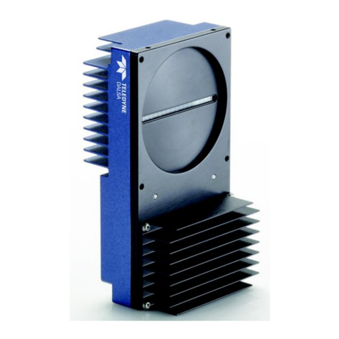
The SP-100 (overview camera) comes from the factory oriented to face the rear of the bus. If
this camera is mounted facing forward the image will be upside down. The SP-210 (license
plate capture camera) can be configured to face either forwards or backwards - see Figure 7.
The cameras should be mounted between the two black rub rails found on most school busses.
See Figure 1. If the bus does not have the black rub rail mount the cameras high enough so
they are not in the spray of the front tires. Do not mount the cameras too high (usually above
4.5 feet from the ground (approximately)). While we want the cameras high enough to avoid
road spray from the tires and passing vehicles we also want to minimize the vertical angle from
the camera to the license plate of passing vehicles.
Park the bus in a location where there is sufficient room on the drivers side to park a vehicle for
camera aiming purposes.

Copyright Gatekeeper Systems 2011 Page 3 of 9
Rev 2.0
The SP100 (overview camera) must be mounted forward of the stop arm aimed towards the
rear. See Figure 1. Note: With some newer busses the front body work is curved inwards.
Before drilling holes test the mounting location to see that it is possible to aim the camera
correctly.
Positioning of the cameras as indicated in Figure 1 typically allows cables to be routed through
interior channels that can be accessed by removing the covers.
The SP-210 utilizes infrared illumination technology. Due to this the image is black and white
and will often appear dark. The reflectivity of the license plate is key for this camera to function
correctly. Aiming the camera at a non reflective surface will often result in a black image. This
is most often seen when the camera is indoors and being tested. This is normal. The only way
to see if the camera is operating correctly is to aim the camera at a reflective license plate.
3M is a major supplier of the reflective material that is used in license plates. 3M guarantees
the plates reflectivity for 5 years. 3M also has stated that a useful life of the reflective plate is
about 7 years. Plates older than 7 year may not have sufficient reflectivity to allow for a clear
image to be captured. In this case the plate will appear gray and the plate characters may not
be readable.
Damaged license plate can also be problematic. If the reflectivity material on a license plate is
damaged or chipped one will see dark spots on the image of the plate.
Note: Other documentation is provided to configure the Gatekeeper Systems N404 DVR and is
not included here.
Mounting and Aiming of Rear Facing SP100 and SP210
Please be aware of the following when positioning the SP210:
oWhen the SP-210 is mounted between the black rub rails on the side of the bus, make
sure there is sufficient room for the protective shroud to be installed on the SP210 frame
after the frame has been screwed to the bus.
oTypically the SP-210 is angled down about 10 to 15 degrees – see Figure 1 for the
relative mounting position. While there is flexibility to angle the SP-210 downward after
the frame is screwed to the bus, it is important to get the aiming as close as possible
before the SP-210 camera frame is mounted to the bus. Be careful to not strip the
supplied TEK screws by over tightening them.
In order to aim the rear facing cameras masking tape should be placed on the road beside the
bus so as to locate the position of a vehicle. Once the position is determined then a vehicle
should be parked in the target position while the camera is being aimed. See Figure 3.
Place masking tape on the ground 22 feet back from the location of the SP-210 and 6 feet out
from the bus. See Figure 2 for geometry. Position a vehicle to be used for aiming at the
masking tape. See Figure 3.
The SP-100 should be aimed so that it captures the bottom of the stop arm when the stop arm
is deployed. See Figure 4.
The SP-100 is provided with a poly base. This is to ensure that the camera is not grounded to
the bus. If the camera is grounded to the bus degraded video may result.

Copyright Gatekeeper Systems 2011 Page 4 of 9
Rev 2.0
Figure 2 – Aiming Geometry For Rear Facing Cameras
Figure 3 Vehicle positioned within tape marks for aiming of the cameras
22 feet
6 feet
School Bus
Target
Vehicle
SP100 Overview
Camera on Side
of Bus
SP210 Camera
on Side of Bus

Copyright Gatekeeper Systems 2011 Page 5 of 9
Rev 2.0
Figure 4 – view from SP100 – Overview camera – The deployed stop arm is at the top of the image
Before drilling any holes in the bus it is strongly recommended that the cameras be held against
the side of the bus and aimed. By connecting a monitor to the “video out” connector of the
Gatekeeper Systems N404 DVR a live image can be viewed.
The positioning of the SP-210 camera is critical.
Again: It is strongly recommended that the SP210 be held against the side of the bus and
aimed before drilling any holes.

Copyright Gatekeeper Systems 2011 Page 6 of 9
Rev 2.0
Use the supplied grommet so that the metal of the bus does not cut into the camera cable when
it is routed through the exterior of the bus.
The SP210 should be aimed so that the resulting image appears as in Figure 5 when the
vehicle is located 22 back and 6 feet away from the bus.
This aiming should be considered preliminary aiming only. It is strongly recommended that final
aiming be done with drive bys when the bus is located on a typical road that it will run on – see
section – Final Aiming
The SP-210 has 2 knobs at the bottom to zoom and focus the camera.
Loosen the two protruding screws on the SP-210, one screw adjusts the zoom level and the
other adjusts the focus. Note: these two adjustments interact with each other so the focus must
to be reset when zoom level is changed. When the correct zoom and focus is achieved, tighten
the screws. Be sure to not over tighten them.
Cable passes through this slot
Fasten supplied Tek screws in the curved slots
Cable passes through this slot
Fasten supplied Tek screws in the curved slots
Cable passes through this slot
Fasten supplied Tek screws in the curved slots

Copyright Gatekeeper Systems 2011 Page 7 of 9
Rev 2.0
Figure 5 – Aiming and zoom example when vehicle is 22 feet back and 6 feet away from the bus.
Locating and Mounting a Second Forward Facing SP-210
In States/Provinces that only require vehicles to have rear license plates a second SP-210 will
be required in order to capture license plate images of vehicles passing a bus in both directions
(back to front and front to back).
Locating and aiming a second, front facing SP-210 is very similar to aiming the rear facing SP-
210
The front facing SP210 should be located behind the stop arm so that it has a clear view of the
target vehicle when the stop arm is deployed and the target vehicle is 22 feet and 6 feet away
from the SP-210 camera. See Figure 6.
It is recommended that a live image be viewed by connecting a monitor to the “video out”
connector of the N404 DVR.
While viewing the live image on the monitor, test position the SP-210 watching for the following:
oField of view is not obstructed by deployed stop arm
oIR from the rear facing SP-210 camera is not visible in the front facing SP-210
oIR from the front facing SP-210 camera is not visible in the rear facing SP-210
Usually the Front facing SP-210 is located approximately 5 to 6 feet behind the stop arm.
Once the position is identified screw the SP-210 to the bus using the supplied Tek screws.

Copyright Gatekeeper Systems 2011 Page 8 of 9
Rev 2.0
Figure 6 – Aiming Geometry For Front Facing Cameras
SP-100 and SP-210 Image Orientation
The SP-100 is shipped for installation facing the rear of the bus. If The SP-100 is mounted facing
forward the image will be inverted. Therefore mount the SP-100 facing the rear of the Bus.
The orientation of the image can be changed in the SP-210. This is required whether the camera is
aimed forwards or backwards. The camera cylinder (inside the SP-210) has a collar secured around
the camera. The collar is attached to the camera cylinder with the middle bolts. See Figure 7. The two
outside bolts secure the collar to the SP-210 mounting base. In order to correctly orientate the image
correctly remove the collar from the mounting base. This is done by removing the two outside bolts.
Flip the camera over and reattach the collar to the mounting base using the bolts.
SP-210 cameras will ship with the correct orientation. However if the orientation needs to be changed,
because the image is upside down, follow the above procedure.

Copyright Gatekeeper Systems 2011 Page 9 of 9
Rev 2.0
Figure 7 – SP-210 Collar and Bolts
Final Aiming
Initial aiming of the SP210 and the SP100 should be done as indicated previously in this
document.
For final aiming it is recommended that the bus be parked in the center of the lane on a
road that it would normally travel on.
Then deploy the stop arm and drive a vehicle past the bus with the Stop Arm camera system
operational.
The vehicle should make two passes – from back to front of bus and then from front to back
of bus.
For the first two passes the test vehicle should be driven very close to the bus in the adjacent
lane.
The next two passes the test vehicle should be in the center of the adjacent lane.
For the last two passes the vehicle should be driven so that it hugs the shoulder of the
adjacent lane.
Review the video and then fine tune the aiming of the SP-210 and SP-100. In most
cases the SP-100 will not have to adjusted however in Gatekeepers Systems
experience the SP-210 usually needs to be fine tuned (with respect to aiming) to
capture the license plates of the passing vehicle.
Other Gatekeeper Digital Camera manuals


