GATEXPERT BC Series User manual
DC Brushless Barrier Gate
BC Series
Instruction Manual
Website: www.gatexpertstore.com
E-mail: sales@gatexpertstore.com

Warning:
Please read this instruction manual carefully before installation, in which contains some
important information about installation, usage, maintenance and safety.
Any undefined operation under this instruction is not allowed. Improper usage will result in
damage to this product and cause serious injury or property losses.
Please keep this instruction manual properly for future reference.
The design and manufacture of the barrier gate is totally complied with the current
standards and regulations.
Considering the possibility of danger, the installation must strictly comply with the following
construction standards and electrical operation procedures:
Before installation, please check if any additional equipment or materials are needed in
order to meet the specific requirements.
The handling of packing materials must comply with local regulations.
Please do not modify any parts, except for those defined under this instruction manual.
Any undefined modification may cause troubles. Any damages to the product arising
therefrom shall be beyond the liability of the company.
Please do not leak water or liquid into the controller or any other open devices. Please
disconnect the power immediately if any mentioned cases happened.
Please keep this product away from heat and open fire. Or it may damage the
components; cause the failure or other hazards.
Nobody is allowed to stand or walk under the barrier boom, especially when it’s on
moving. Please do not stand or leave any objects within the boom rotation range of 90°
due to the collision by cars.
Spring adjustment, operation mode setting, induction devices installation must be
operated by qualified professionals.

WARRANTY
1. To repair against this warranty card and invoice during the warranty period.
2. Warranty period: 1 year after the date of invoice.
3. Without unauthorized dismantling, any product broken or damage due to
quality problem, we’ll offer the repair service for free or replace for free.
4. The malfunction and damages caused by incorrect use or man fault is not
covered by this warranty.
CONTACT US
E-mail: sales@gatexpertstore.com
Please fill in the order information in the form below.
All personal information you provided will be only used for warranty service
and kept strictly confidential.
Refer to this list when contacting GATEXPERT for technical service or
assistance with your automatic gate opener.
Order Number
Product Model
Purchase Date
Country / Region
Email Address
Issue Details

Table of Contents:
1. Product Outline………………………………………………………………………………..1
2. Functions and Features………………………………………………………………………1
3. Technical Parameter List……………………………………………………...……………..2
4. Machine Components………..….…..……………………………………………………….3
5. Installation Direction................………………………………………………………………3
6. Assembly and Installation……………………………………………………………………4
6.1. Pre-Installation Check……………………………………………………………………..4
6.2. Basic Structure Installation………………………………………………………...……..4
6.3. Boom Balance Adjustment………………………………………………………………..6
6.4. Mains Wiring…………………………………………………………….………………….7
6.5. Electrify Check………………..……………………………………………………..….....7
6.6. Vertical Adjustment of Barrier Boom ………………………….……………...………....8
6.7. Manually Open/Close………………………………………………………………….….8
6.8. Spring Configuration……………………………………………………………………..10
7. Control Board Wiring……………………………………………………………….……….11
7.1 Terminal Instruction……………………………………………………………………….12
7.2 Setting Button Instruction…………………………………...……………………………13
7.3 Parameter Setting......……………………………………………………………………13
8. Technical Support………………………………………………………...…………………15
9. Packing List…………………………………………………………………………………..16
10.Terms of Service……………………………………………………………...………….….17

1
1. Product Outline
On the basis of absorbing essence of similar products at home and abroad, the company
has researched and developed this BC series DC brushless barrier gate. This product
adopts international advanced technology, with mechanical and electrical integrated
design, which fully realizes automation and intelligence of operating, brings convenience、
safety and speed for using.
2. Functions and Features
Efficient DC brushless motor and precise gear reducer drive with mechanical and
electrical control integrated. More flexible and convenient operation, safe and
reliable for using, completely maintenance free during its service time.
Adopts precise four-bar linkage mechanism and spring balance device which enable
the barrier boom work with soft start-slow stop function in fast and stable without any
impact. Reduces the driving power in maximum, extends its service life.
Integrated machine core, small size with large power, wall-mounted installation, easy
for assembling and disassembling.
DC 24V low voltage brushless motor, adapts to global voltage (110~220±15%). It
highlights for safer use, less noise, low heat output, frequently use, energy
conservation and environmental protection.
The combination of motor hall encoder and control unit ensures the control to
mechanism moving position at the utmost.
The dedicated controller system has high integration and strong logic performance. It
can be connected with any toll system of roads and bridges、parking lots and so on.
Intelligent speed adjustment efficiently reduces the trembling of the barrier boom,
suitable for different occasions.
High-sensitivity Auto-reverse function will prevent incorrect operation and other crash
or hitting accidents.

2
Open first anti-smash function: barrier boom will perform opening action once received
an opening signal during the closing process.
Humanized anti-collision boom dropping-out mechanism, when the vehicle
accidentally hits the barrier boom, the anti-collision mechanism will rotate the boom
to avoid damage to the vehicle and the barrier gate.
High-strength precision cast steel machine case, with outdoor metal powder
electrostatic spraying surface treatment, waterproof and dustproof, protection class
up to IP54.
3. Technical Parameter List
Barrier Model
BC3015
BC4020
BC5035
BC6050
Boom Length
Round boom
φ75, ≤3m;
Octagonal boom
80×46, ≤3m
Round boom
φ75, ≤4m;
Octagonal boom
80×46, ≤4m
Octagonal
boom 100×45,
≤5m
Octagonal
boom
100×45, ≤6m
Open/Close Speed
1.5 sec
2.0 sec
3.5 sec
5.0 sec
Transmission Ratio
1:60
1:120
Max. Power
140w
Power Supply
AC110-240V±15%
Machine Case
1.5mm Steel Plate
Machine Case Size
(W×D×H)
350 × 320 × 1020mm
Net Weight
45kg
Operating Temperature
Range
-40~+60 ℃(temperature under -20℃should be equipped with
electric heating plate)
Driving Method
Brushless DC motor + Helical gear reducer
IP Grade
54
Insulation Class
F
Relative Humidity
≤ 85%
Motor Unload Speed
2400r/min
Service Life
5 million times
Remote Control Distance
≤ 30m (empty environment, sunny weather)
Running Noise
<50dB
Surface Treatment
Outdoor metal powder electrostatic spraying
3
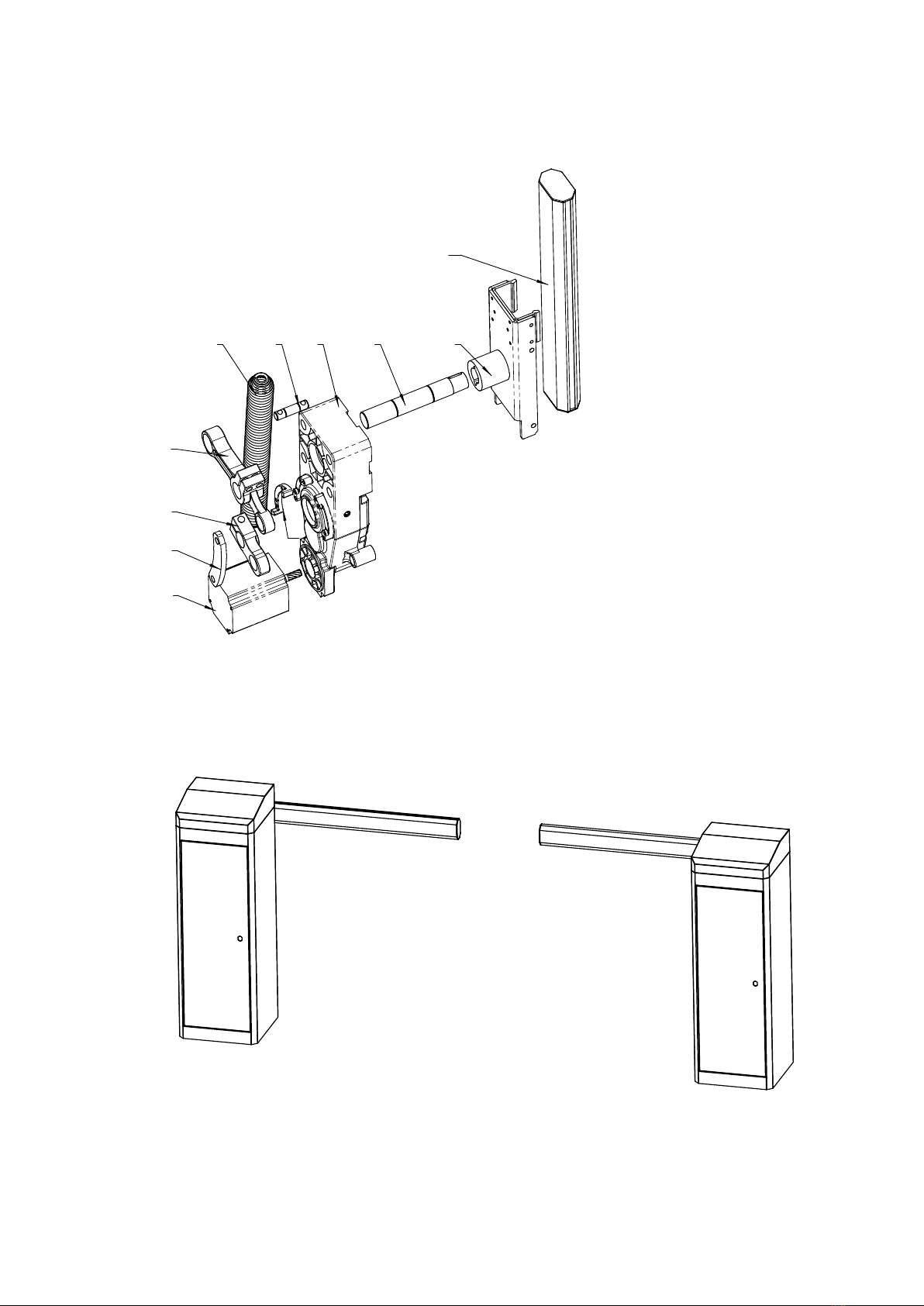
4. Machine Components
1
2
3
4
5678 9
1010
1111
1
2
3
4
5
6
7
8
9
1010
MotorMotor
LinkLink rodrod
CrankCrank armarm
RockerRocker springspring armarm
SpringSpring
SpringSpring rod(upper)rod(upper)
ReductionReduction gearboxgearbox
OutputOutput shaftshaft
BoomBoom traytray headhead
BoomBoom
Figure 1
5. Installation Direction
Leftward Fixed Rightward Fixed
Figure 2
4
6. Assembly and Installation
6.1 Pre-Installation Check
Note:
Barrier gate installation must be carried out by qualified technician; Installation must
comply with relevant regulations. Before installation, please read this instruction manual
carefully.
Please definite the installation direction of the barrier gate to be Leftward or Rightward
fixed.
Please make sure that the boom will operate freely without any impediment.
Please make sure the mounting base is strong enough and the size is suitable.
Please make sure the installation spots for all the relative equipment are suitable to
avoid any collision.
Please check the accessories according to the packing list (page 16)
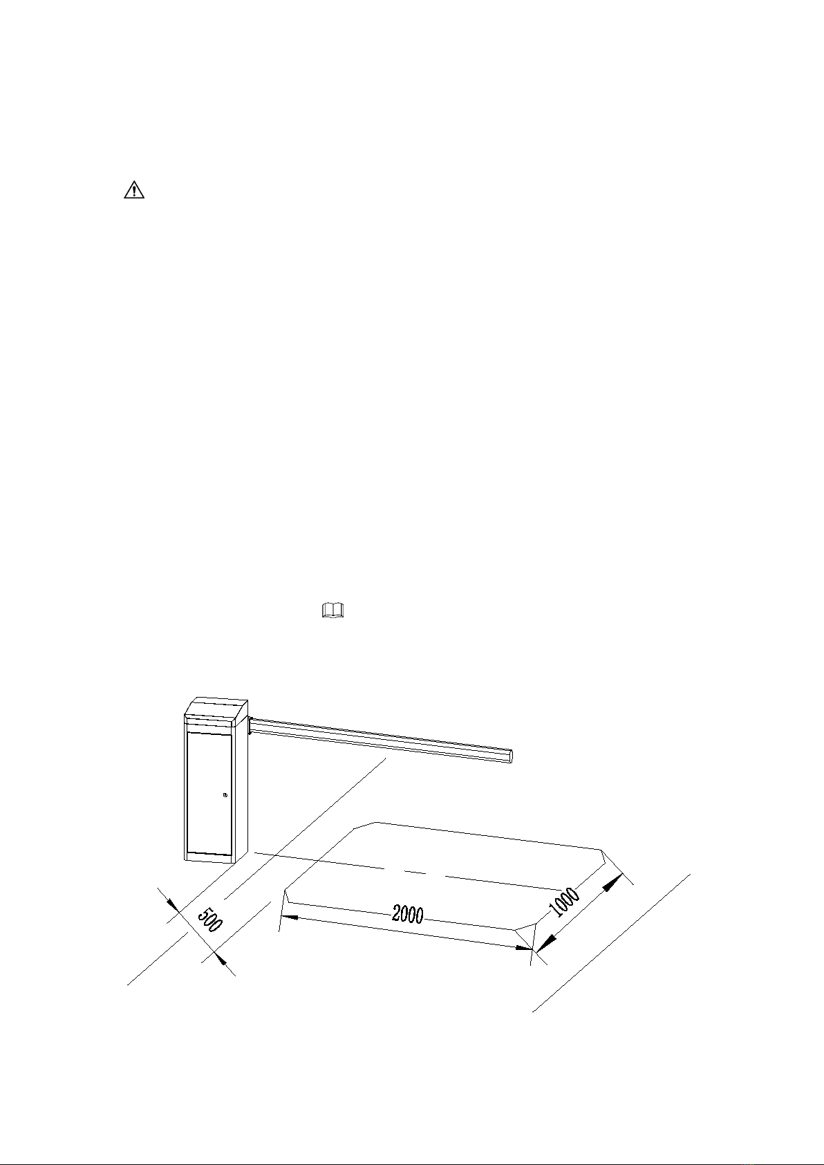
6.2 Basic Structure Installation
Coil Installation Instruction :
Position of the induction coil: The general size of induction coil size is 2m(L) x 1m(W), its
central axis should be right under the barrier boom, please refer to the figure 3.
Figure 3

5
Fastening Screws Installation Instruction :
If the installation site didn’t set with a foundation, then please make sure that the
installation ground is strong enough to be fix with the barrier gate. Drill holes for fastening
screws with diameter of 16mm, depth of 80mm, drive the M12 x 150mm fastening screw
into the hole, then tighten the nut before withdrawing it.
If the installation site is concreted with foundation, please make sure the foundation depth
is over 500mm, and the foundation area is over 450 x 450mm. Please pre-buy 3pcs PVC
wiring tubes with diameter of 25mm: 1 for induction coil wiring, which should be led
towards roadside and should be 50mm underneath the ground. The other 2 tubes are for
power supply and control unit wiring. Meanwhile, users can embed 4pcs M12 foundation
screws and leave 70mm of the screw thread over the ground, keep a distance of 170 x
170mm; Or users can drill the hole after the foundation hardening, and use the equipped
expansion bolts to finalize the installation, please refer to Figure 4.
Barrier Gate Installation Instruction :
Put the barrier gate in the right place (Keep the boom dropping-out and vehicle passing on
the same direction), make sure the barrier gate is vertical to the ground, align the press
board to the anchor bolts, lock and fasten them.
Barrier Boom Installation Instruction :
Place the barrier boom into boom tray, add plastic gasket on both sides, use the spanner
to clamp the boom by screws nuts. Please refer to Figure 5.
170
170
450
450
500
50
Figure 4 Figure 5
6
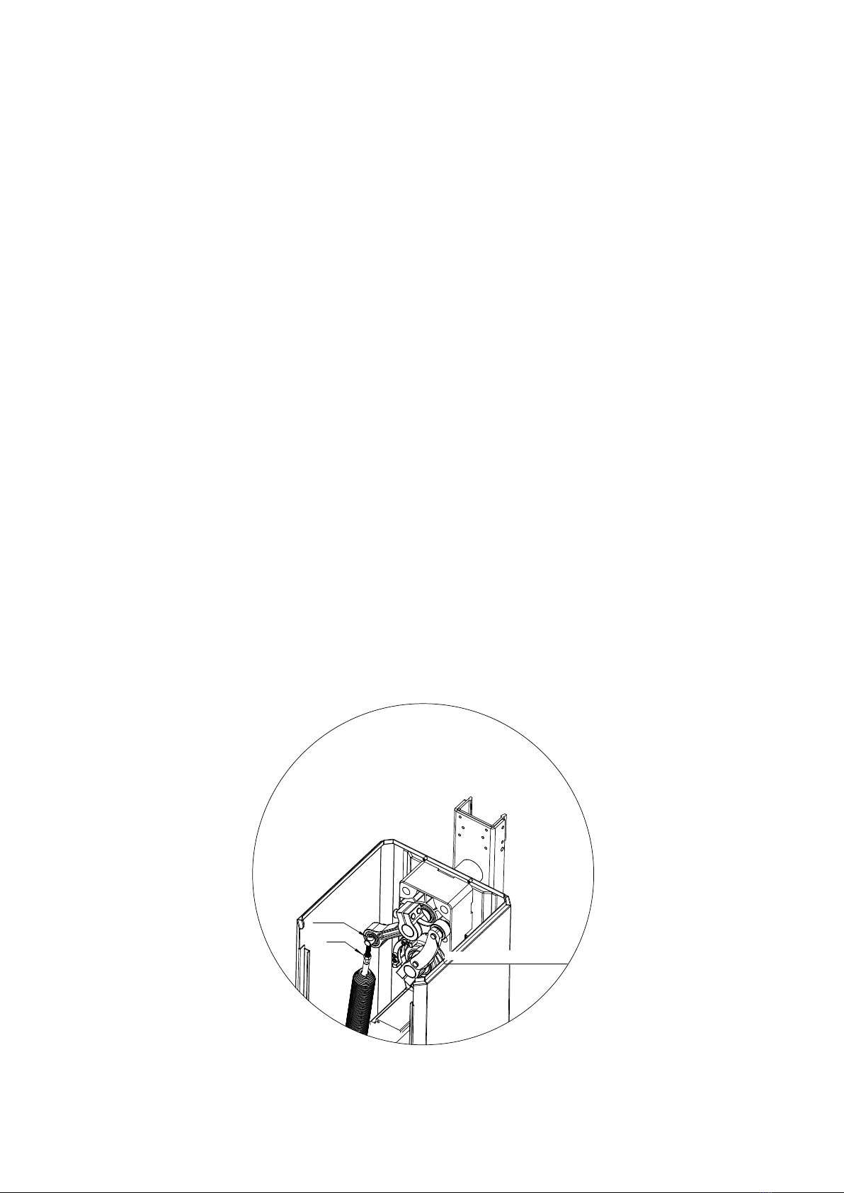
6.3 Boom Balance Adjustment
The tension of the spring is related to the boom length, the spring has been assembled in
the factory according to the different boom length, also the relative adjustments on
operating speed 、operating balance during opening/closing process has been set up
before delivery. Spring tense must be re-adjusted by professionals if there were any
changes on the boom length or weight. Please check and adjust according to the following
steps.
1. Open the barrier gate side door and remove the upper cover.
2. Unplug the power cord.
3. Toggle the crank from the side door to unlock it(refer to column 6.7), manually adjust the
boom to the place of 45 degrees then release the hand. If the boom keeps stable on the
place of 45 degrees’ angle, indicating that it is with the best spring force.
4. If the spring force is too large or too small, then should be adjusted. First, loosen the
nut on the top of the spring, clockwise rotating the screw to increase the tension of the
spring, counter-clockwise to decrease, then adjust the barrier boom again to its 45
degrees’ angle position to check the spring tension.
5. Through repeating the above forth step to adjust the boom to its best balance, then
fasten the double nuts, adjustment is complete.
ScrewScrew
NutNut
PressPress downdown toto unlockunlock
PressPress downdown toto unlockunlock
Figure 6
7
USE USE LED1
AC BATTERY
POWER SELECT
SW1
24V+
+ 24V -
CON2
P3
Connect to
Control Unit
L N PE
AC INPUT
ON
OFF
I
O
SW1
switch to USE AC
+ -
24V OUTPUT
POWER
AC100-240
INPUT
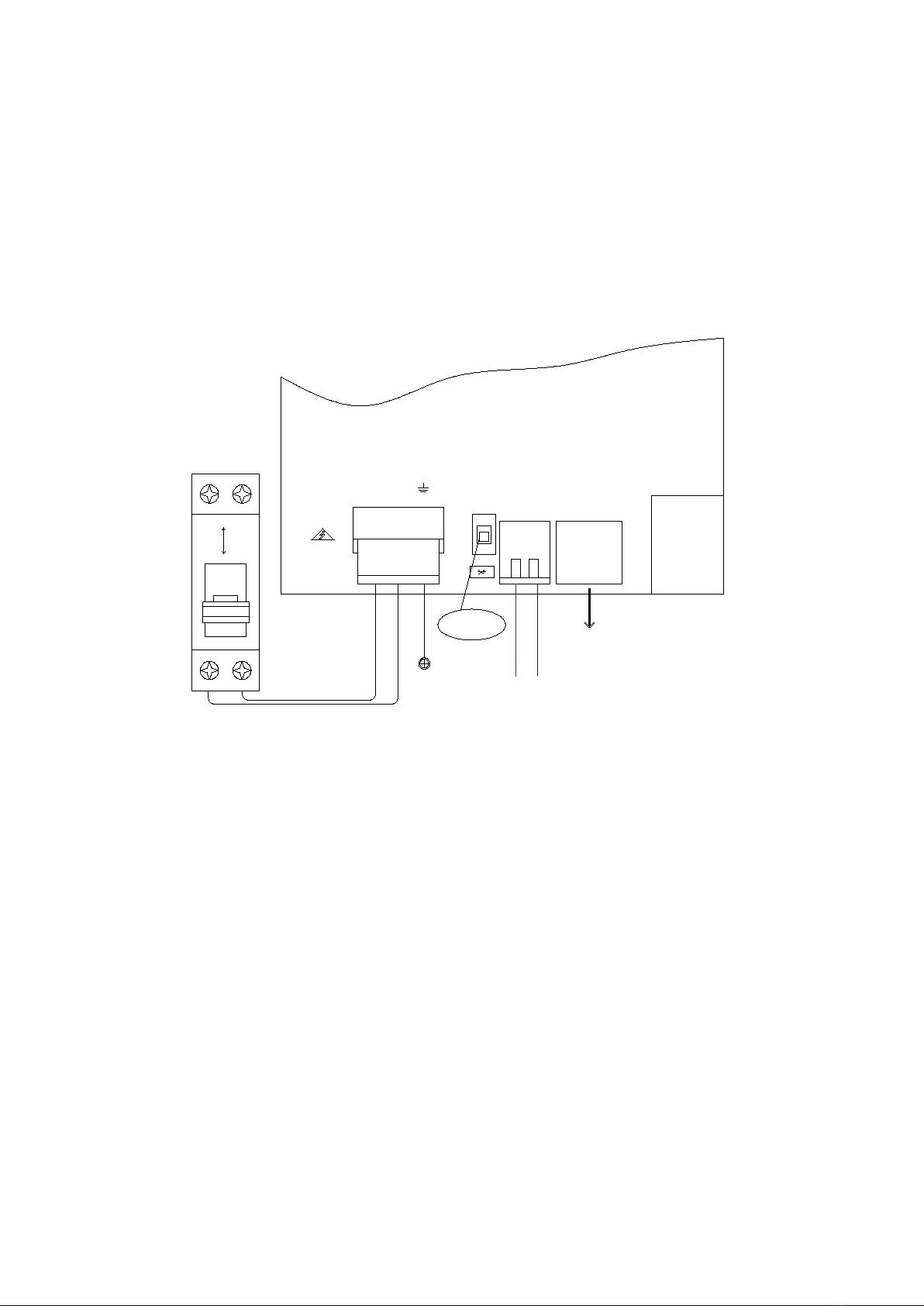
6.4 Mains Wiring
The power module of the barrier gate has been connected to the control board before
delivery. To ensure operational safety and avoid damage to the components, please
disconnect the circuit breaker first, and then connect the L and N of AC power into the
input port of circuit breaker.
Figure 7
Note: Only professional technicians can engage in the installation and after sales
maintenance for this product and are responsible for any damage caused by
improper operation.
6.5 Electrify Check
Please close the circuit breaker to connect the power after correctly wired. The indicator
light on the control board will be on once the power is connected; After powering on,
please press the open/+ and close/- buttons on the remote control, barrier gate will
automatically detect the opening/closing limit switch (both limit switches are required to be
detected). After detecting the opening/closing limit switch, the auto-detecting data will be
saved automatically, after which, the barrier gate will work properly.
8
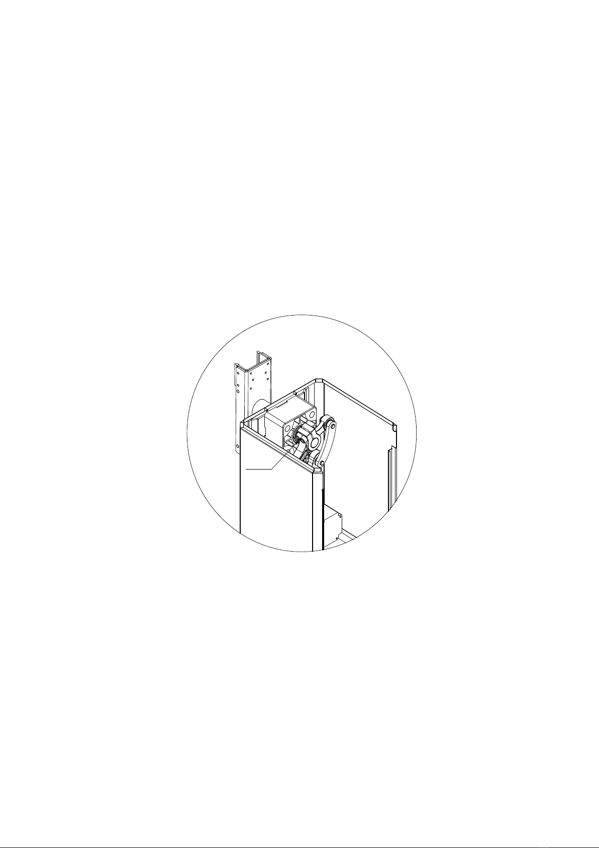
6.6 Vertical Adjustment of Barrier Boom
If the barrier gate boom cannot open to its vertical position or close to its horizontal
position. Please take the following steps to adjust it:
1. Open the barrier gate door, unplug the power cord.
2. Open and remove the upper cover.
3. Loosen the two fasten screws on rocker spring arm when the barrier boom is in erect.
Adjust the boom to its horizontal position by hand. Use the torque wrench to tighten the
two fastening screws (locking force is 72 N·m)
4. Connect the power to work, check whether the boom opens/closes in place. If not,
please re-adjust it after power off until the performance achieving the ideal state.
ScrewScrew
Figure 8
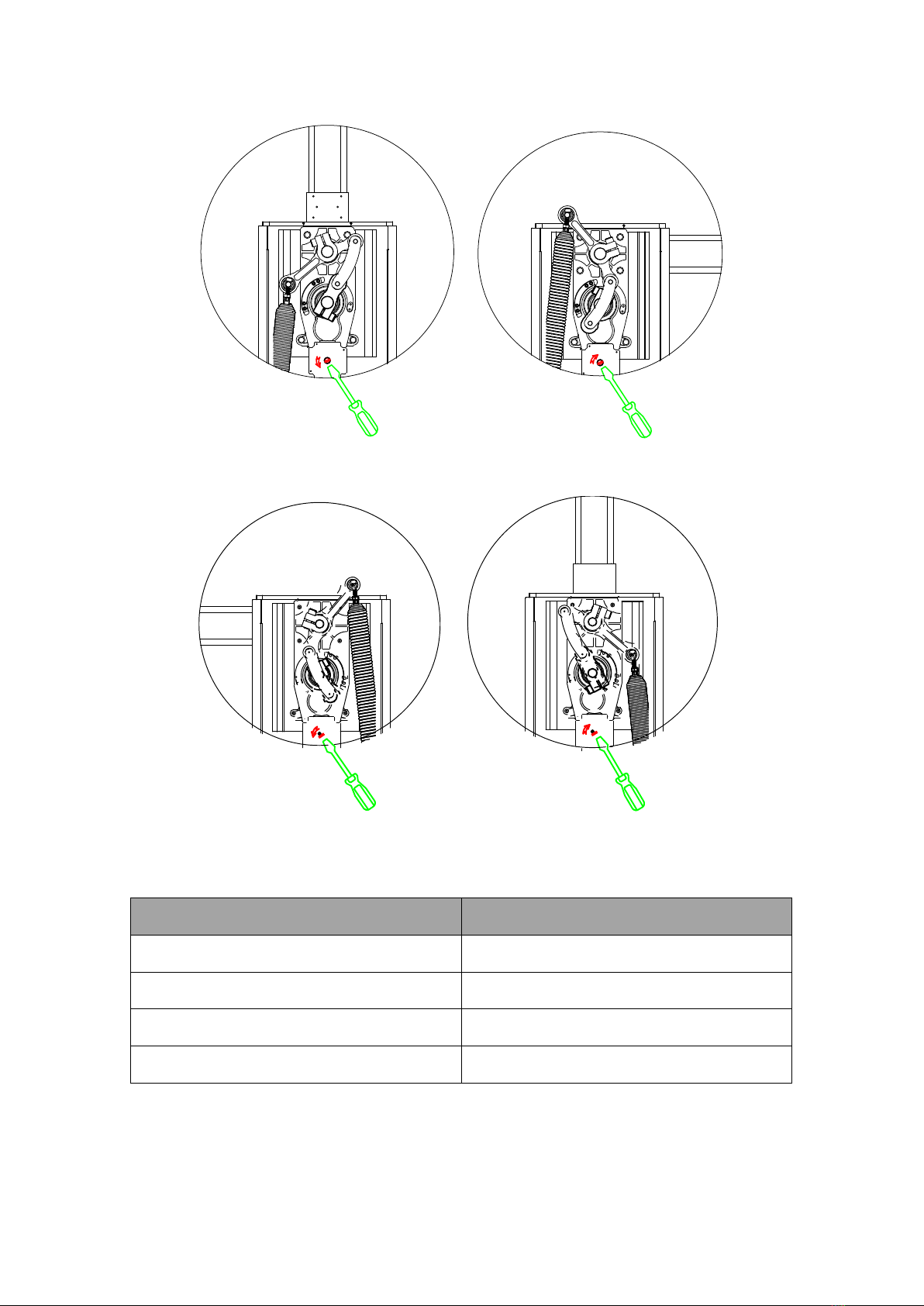
6.7 Manually Open/Close
The barrier boom may stay in the vertical or horizontal position when power is off, by this
time the barrier gate mechanism is on its self-locking position. If you need to open/close
the barrier by hand at this time, please follow the steps as below:
1. Open the barrier gate door.
2. Unplug the power cord.
3. For Leftward fixed type:
To close when boom in opened position, please counter-clockwise rotate the motor shaft

9
with a specific tool to enable the barrier boom to move, after which barrier boom can be
manually pressed down for closing.
To open when boom in closed position, please clockwise rotate the motor shaft with a
specific tool to enable the barrier boom to move, after which barrier boom can be manually
lifted up for opening. Please refer to Figure 9.
4. For Rightward fixed type:
To close when boom in opened position, please counter-clockwise rotate the motor shaft
with a specific tool to enable the barrier boom to move, after which barrier boom can be
manually pressed down for closing.
To open when boom in closed position, please clockwise rotate the motor shaft with a
specific tool to enable the barrier boom to move, after which barrier boom can be manually
lifted up for opening. Please refer to Figure 10.
Note: Please stabilize the boom when manually open it, in order to avoid any
unnecessary damage caused by the spring tension.
10
Figure 9
Figure 10
6.8 Spring Configuration
Boom Length
Spring
3M Octagonal Boom 80x46 mm
Φ4.5x1pc
4M Octagonal Boom 80x46 mm
Φ5.5x1pc
5M Octagonal Boom 100x45 mm
φ4.5 x1pc; φ5.5 x1pc
6M Octagonal Boom 100x45 mm
φ5.5x2pcs
Note: If the boom length is shorter than 4m, it’s recommended to use 80x46mm
octagonal boom, if length is longer than 4m, to use 100x45mm octagonal boom.

11
7. Control Board Wiring
Figure 11
Warning!
The controller of this product is specially designed for the use of low speed and medium
speed barrier gates. The position of the barrier boom will be continuously detected by the
motor hall during running, which replaces the limit switches used in conventional barrier
control systems.

12
The combination of the hall encoder and the controller unit ensures the maximum control
to the boom optimum running position.
Note!
For other special functions, please note that the controller's wiring may differ from which
shown in this wiring illustration.
Important Note:
All input signals (like push buttons, limit switches, etc.) must be connected in the volt-free
contact way.
7.1 Terminal Instruction
Motor Terminal: Insert an 8 ends motor cable terminal;
Power Terminal: Insert a 2 ends power cable terminal;
Light Sensor Terminal: Insert a 2 ends light sensor terminal;
External Remote Terminal: Insert a 3 ends external antenna terminal;
12V+/GND Terminal: Output +12V, maximum output current is 1A;
NA Terminal: Extended terminal;
Open in Place: When the barrier boom is open in place, the 2 terminals will be NC;
Closed in Place: When the barrier boom is closed in place, the 2 terminals will be NC;
OPEN: OPEN signal input terminal (another end connects with +12V terminal);
CLOSE: CLOSE signal input terminal (another end connects to +12V terminal);
STOP: Halfway stop during opening or closing signal input terminal (another end
connects to +12V terminal);
Radar/Loop Detector: Connect with radar or vehicle detector;
Obstacle Detector: Connect with vehicle detection coil only.
LED Display Instruction :
Display
Instruction
IDLE
Not connect to the machine, or hall sensor failure.
Possible reason: wiring loose.
STOP
Closed in place
CLOS
Barrier gate in closing

13
OPEN
Barrier gate in opening
HOLD
Open in place
LOCK
Barrier gate locked
7.2 Setting Button Instruction
There are 4 buttons on the control board for setting all the parameters: open/+, close/-,
menu/confirm, stop/cancel.
Open/+: Under normal working mode, press this button, barrier will open. While control
board in setting mode, pressing this this button will increase the value, press and hold this
button, the value will be increased to the max. then start over again from the bottom value.
Close/-: Under normal working mode, press this button, barrier will close. While control
board in setting mode, pressing this this button will decrease the value, press and hold
this button, the value will be decreased to the minimum. then start over again from the top
value.
☰/OK: There are 3 functions on this button:
1. Under normal working mode, press and hold this button for 3 sec. to enter into menu
selection, LED will display “F-XX”, press “+” or “-” to select the menu you are going to set.
2. Under menu selection status, short press this button will enter into parameter setting.
3. Save the setting after parameter confirmed.
□/CL: Under normal working mode, press this button, barrier will stop; Under parameter
setting status, pressing this button will return to previous menu.
7.3 Parameter Setting
Press and hold “menu” button on the control board for 3 sec. to enter into parameter
setting mode, the LED will display “F-XX”. Short press “+” or “-” button to select the
corresponding menu, press “menu” to enter into the setting, press “stop/cancel” button to
return to previous menu or exit the setting. After finished the setting, press “menu” to
complete. The system will exit the setting mode after 60 sec. without setting action.
Menu
Function
Default
Value
Range
Mark
F-00
Open speed
60
10-100
The larger the number is, the

14
faster the speed will be.
F-01
Close speed
60
10-100
The larger the number is, the
faster the speed will be.
F-02
Slow open position
70
45-80
The position that barrier starts to
run at a slower speed during
opening. Unit: degrees
F-03
Slow close position
45
10-60
The position that barrier starts to
run at a slower speed during
closing. Unit: degrees
F-04
Open acceleration
time
30
0-255
Acceleration time from 0 to F-00
during opening. Unit: 0.01 sec.
F-05
Close acceleration
time
30
0-255
Acceleration time from 0 to F-00
during closing. Unit: 0.01 sec.
F-06
Open in place speed
10
1-100
F-07
Close in place speed
20
1-100
F-08
Horizontal position
adjustment
6
1-255
Slightly adjustment on barrier
boom horizontal position.
F-09
Vertical position
adjustment
6
1-255
Slightly adjustment on barrier
boom vertical position.
F-10
Automatic close time
without loop detector
0
0-255
Automatic closing time for no car
passes.
Unit: sec.
F-11
Obstacle Detection
0
0-1
1:Enable 0:Disable
F-12
Delay time of closing
after vehicle passed
2
0-255
Unit:0.1 sec.
F-13
Travel auto-learn
speed
40
0-80
Barrier will run at this speed to set
the open and closed limit switch.
F-14
Remote control
pairing
0
0-60
F-15
Auto-reverse
response time after
meeting obstacle
10
1-40
Response time when meeting
obstacles. Unit: 0.05 sec.
F-16
Obstacle detection
sensitivity
10
1-40
The larger the number is, the less
the sensitivity will be.
F-17
Motor direction
0
0-3
Motor polarity and rotating
direction.
F-18
Locked current
6
0-15
Danger, set it with caution! The
larger the number is, the larger the
locked current will be.
F-19
Loop detector count
0
0-10
No counting for loop detector by
default.
F-20
Auto-testing
0
0-255
Automatic testing interval,this can

15
be used for burn-in test. 0 means
the normal working mode.
F-21
Restore factory
setting
0
0-255
5:Delete all remote controls 10:
Restore factory setting
F-28
Slow close angle
30
0-45
The angle that barrier starts to run
at a slower speed during closing.
Unit: degrees
F-29
Relay output mode
0
0-5
For different relay type
F-38
Slow open angle
90
45-100
The angle that barrier starts to run
at a slower speed during opening.
Unit: degrees
F-69
Remote control mode
0
0-1
0: Remote control in three-button
mode
1: Remote control in single-button
mode
8. Technical Support
The control unit comes with an error code display feature that allows the user to determine
the errors. For details, please refer to the following instruction of each error code.
Error Code
Cause
E-00
While operating the remotes deletion or restore factory setting,
should set the correct value.
Incorrect value will feedback this error.
E-03
Opening blocked. Possible reason: the balance spring is broken or
opening speed is too slow or open in place speed is too slow.
Solution: increase the opening speed or open in place speed.
E-04
Closing blocked. Possible reason:spring tension is too tight, boom
not fixed, closing speed or closed in place speed is too slow.
Solution: to check the spring tension, confirm boom is fixed,
increase the closing speed and closed in place speed.
E-05
Opening overtime, opening time should be in 15 sec.
Solution: to increase the opening speed or open in place speed.
E-06
Closing overtime, closing time should be in 15 sec.
Solution: to increase the closing speed or closed in place speed.
E-07
Motor type wrongly selected.
Solution: set under menu F-17 to modify to correct type.
E-08
During opening, the spring is broken and caused the motor reverse.
E-09
The remote control has been paired before, no need to pair again.
E-10
Pairing of remote control exceeds the maximum quantity.

16
If there is any operation failure that can ’t be handled by your technical staff, please
contact our authorized service representative or professional assistance.
Please provide the barrier gate model, product serial number, controller version and other
information when contact us for technical support services, which you can find in the
barrier gate machine case model plate.
9. Packing List
Number
Title
Qty
Picture
Note
1
Barrier gate machine
1
Included in machine
package
2
Machine case press
board
2
3
Expansion bolt M12
4
4
Remote control
2
5
Case Key
2
6
Instruction
1
7
Unlock tool
1
8
Barrier gate boom
1
Optional, separate
package
9
Boom holder
1
Optional
10
Expansion bolt M8
4
Optional, for fixing
boom holder
11
Plug-in Machine control
1
Optional
This manual suits for next models
4
Table of contents
Popular Control System manuals by other brands

Contro l4
Contro l4 Control4 Smart Home quick start guide

GSM Activate
GSM Activate GSM Auto Dialler Plus manual

Almaco
Almaco Seed Spector LRX Operator's manual

HySecurity
HySecurity WedgeSmart DCS installation instructions

SITGroup
SITGroup Proflame instruction manual

HIK VISION
HIK VISION DS-K3B530X Series user manual


